BlueNova CPS 5000-Vic 5.2k User manual

Installation Manual
CPS 5000-Vic 5.2k

Table of Contents
A. INTRODUCTION
1. GENERAL INFORMATION
2. DOCUMENT SCOPE
3. TERMINOLOGY
B. SAFETY FIRST
1. CRITICAL SAFETY REQUIREMENTS
2. WARRANTY REQUIREMENTS
C. STRUCTURAL INFORMATION
1. LIST OF COMPONENTS
2. PRODUCT LAYOUT
D. INSTALLATION
1. PRE-INSTALLATION
1.1 Product Applications
1.2 Requirements & Limitations
1.3 Wiring Diagram
2. STANDARD INSTALLATION (UPS APPLICATION)
3. ADDING SOLAR (PV APPLICATION)
E. BATTERY OPERATION
F. OPERATING INSTRUCTIONS
1. INVERTER
2. BATTERY DISPLAY PANEL
G. EMERGENCY & FIRST AID
A. Introduction
1. GENERAL INFORMATION
Congratulations on purchasing a high-quality BlueNova® product.
2. DOCUMENT SCOPE
This is a technical support document applicable to the following product(s):
-BlueNova® CPS 5000-Vic 5.2k
The information in this document includes the following
-Product Assembly & Installation Procedures
-Operating Instructions
-Maintenance & Troubleshooting Guidelines
-Emergency Procedures
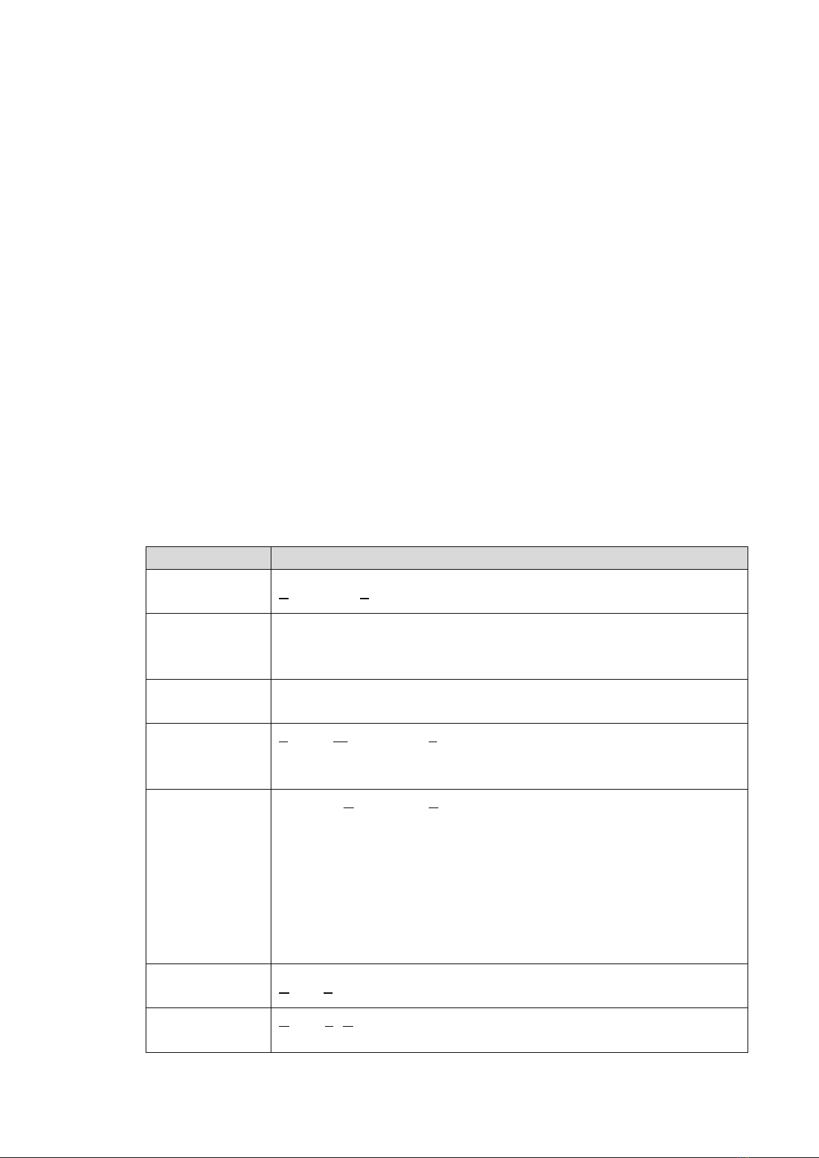
3. TERMINOLOGY
The table below contains an alphabetical list of industry-specific abbreviations as well as
product-specific terms used throughout this document:
Term
Definition
AC
(abbr.)
Alternating Current (as supplied by utilities & most generators).
Battery
(term)
A product subcomponent, in this case specifically 1 x BN52V-100-
5.2k DU (Daily Use) Lithium Iron Phosphate battery.
See: G. Supporting Documents for more technical information.
Battery Pack
(term)
Two or more BN52V-100-5.2k DU batteries connected to each other
in parallel, up to a maximum of 9.
BMS
(abbr.)
Battery Management System: Battery-integrated electronic circuitry
& components. Supports cell health, product safety & peripheral
compatibility functionalities.
DB
(abbr.)
Electrical Distribution Board.
Site DB refers to the main electrical distribution board (if available)
of the building or site at which the product will be installed.
DB-A or DB-B refers to either one of the two electrical distribution
boards integrated as subcomponents within the CPS5000 system
(see: C. Structural Information - 1. Product Layout)
DC
(abbr.)
Direct Current. Batteries & solar panels supply DC.
DoD
(abbr.)
Depth of Discharge. Refers to a percentage of the total available
energy capacity of a battery or battery pack.
MPPT
(abbr.)
Maximum Power Point Tracker: An integral component in modern
solar systems, mainly supportive towards the stabilisation of solar-
supplied energy to the rest of the system.
Product
(term)
Refers to a complete (read: fully assembled) CPS 5000-5.2k system.
Subcomponent
(term)
Refers to one or more of the main functional components that the
CPS system consists of (as illustrated in section C. Structural
Information - 1. Product Layout) below. Does not refer to screws,
wiring & other small system components.
SoC
(abbr.)
State of Charge: A percentage value indication of the amount of
energy stored within a battery.
SoH
(abbr.)
State of Health: A percentage value indication of the amount of
energy capacity that a battery has retained at any point during its
service life. Conversely indicates the percentage with which a
battery has faded (read: lost capacity) from being used over time.
UPS
(abbr.)
Uninterruptable Power Supply
B. Safety First
1. CRITICAL SAFETY REQUIREMENTS
IMPORTANT: Failure to adhere to any one or more of the requirements listed below may
result in serious personal injury or death. For your own safety, it is therefore of utmost
importance that any & all requirements listed below are strictly adhered to:
-Product installation & maintenance should be performed by a qualified electrical
installer or authorised BlueNova® representative only.
-Do not crush, burn or incinerate the product or any of its subcomponents.
-Ensure that product-integrated battery/batteries are fully recharged at least once
every 3 months in accordance with maintenance procedures listed in this document
while/whenever the product is non-operational and/or in storage.
-Do not install the product in direct sunlight. Do not expose the product or any of its
subcomponents to ambient and/or direct temperatures exceeding 55°C.
-Avoid short-circuiting battery terminals. Do not connect batteries to any peripheral
subcomponents in reverse polarity.
-Always disconnect the product from external power sources before commencing with
maintenance procedures. In some cases, disconnecting the battery or battery pack
might also be required. Read maintenance instructions carefully.
-This product has been designed for general home use. It should not be used to supply
power to life-sustaining medical appliances, automotive systems or other devices
from which interrupted operation may lead to damage, personal injury or death.
-Always wear the necessary protective gear during installation and/or maintenance.
2. WARRANTY REQUIREMENTS
This product consists of various subcomponents, some of which include individual
warranties supplied by the manufacturer and/or distributor in each case. Please see
G. Supporting Documents for full documentation of BlueNova product & workmanship
warranties, as well as third-party supplier warranties.
IMPORTANT: The application for which this product is installed might require integration
with existing on-site electrical systems and/or components. Depending on the extent of
such installations, a Certificate of Compliance might have to be obtained following
completion of such installations, as per South African legislature. CoC documents issued in
this regard should be kept safe & will be supportive in the event of future warranty claims.
For installations outside the borders of South Africa, any local legislative requirements
and/or laws comparable to the above should also be adhered to, following installation,
especially if some similar form of certification can be obtained.
C. Structural Information
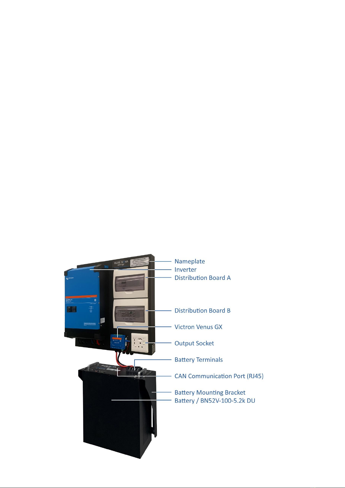
1. PRODUCT LAYOUT
A CPS 5000-Vic 5.2k system consists of 2 x main wall-mountable sections.
The top section consists of a backboard which houses the inverter, distribution boards &
output socket sets, while the bottom section consists of a bracket supporting a LiFePO4
battery:

The distribution boards in the top section contain the following components:
The diagram below illustrates the layout of the unit’s BN52V-100-5.2k DU battery:
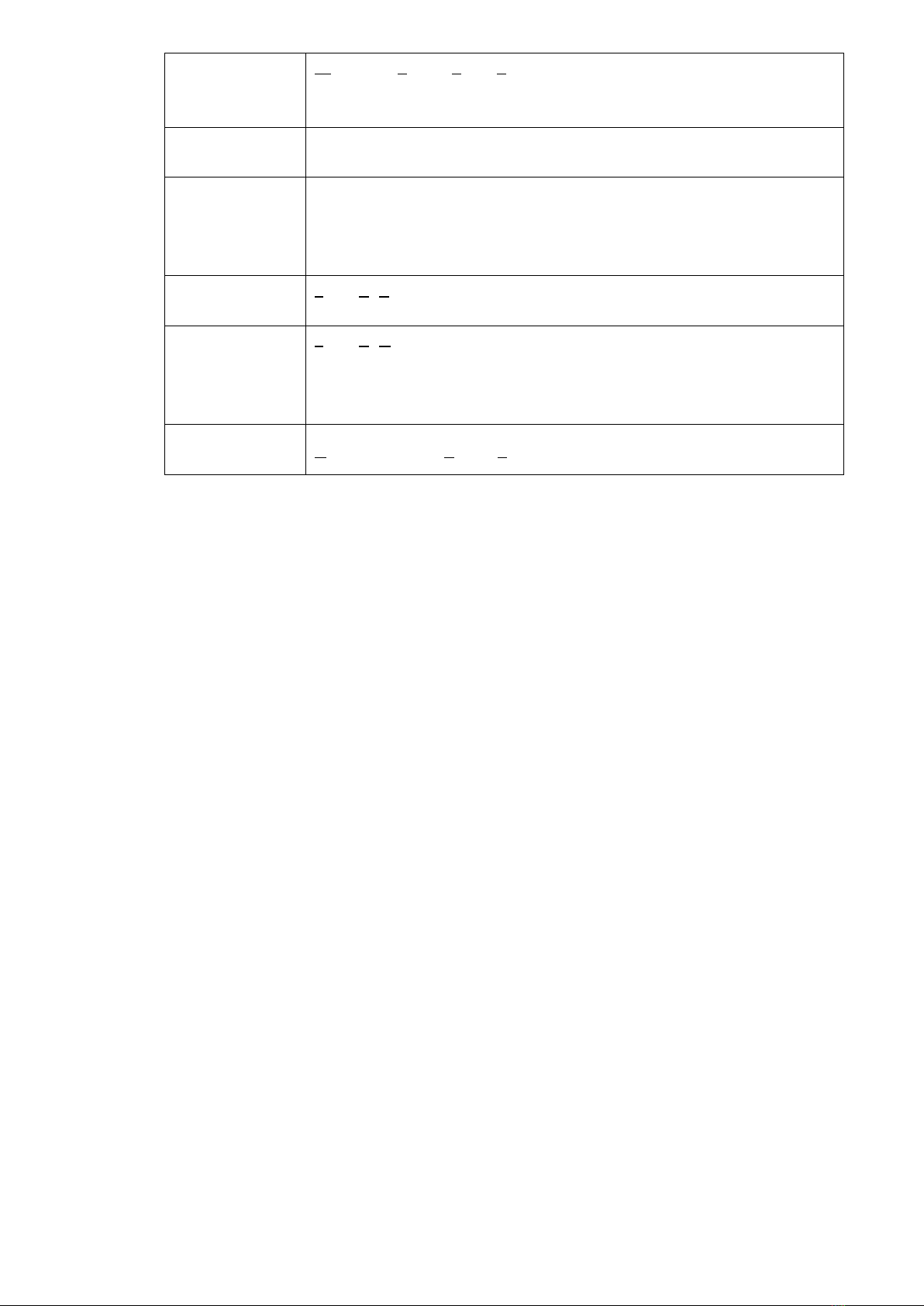
2. LIST OF COMPONENTS
Each CPS5000-Vic 5.2k product is packaged for shipment in 2 x boxes. Please check the
contents of each box upon delivery to ensure that you have received all the components
& quantities listed below:
Box 1: Top unit
Qty
Specifications / Notes
Backboard, including:
-Inverter (pre-installed)
- DB’s & breakers (pre-installed)
- Socket sets (pre-installed)
1
Powder-coated steel
1
Victron Multiplus II 5kVA
2
See D. Installation for more info
2
Compliant to latest industry standards
Rawl bolts
4
For mounting the backboard section
Box 2: Bottom unit
Qty
Specifications / Notes
Battery
1
BN52V-100-5.2k DU (Daily Use)
Lithium Iron Phosphate battery
Battery mounting bracket
1
Single bracket (supports 1 x of the above
batteries), powder-coated steel.
D. Installation
1. PRE-INSTALLATION
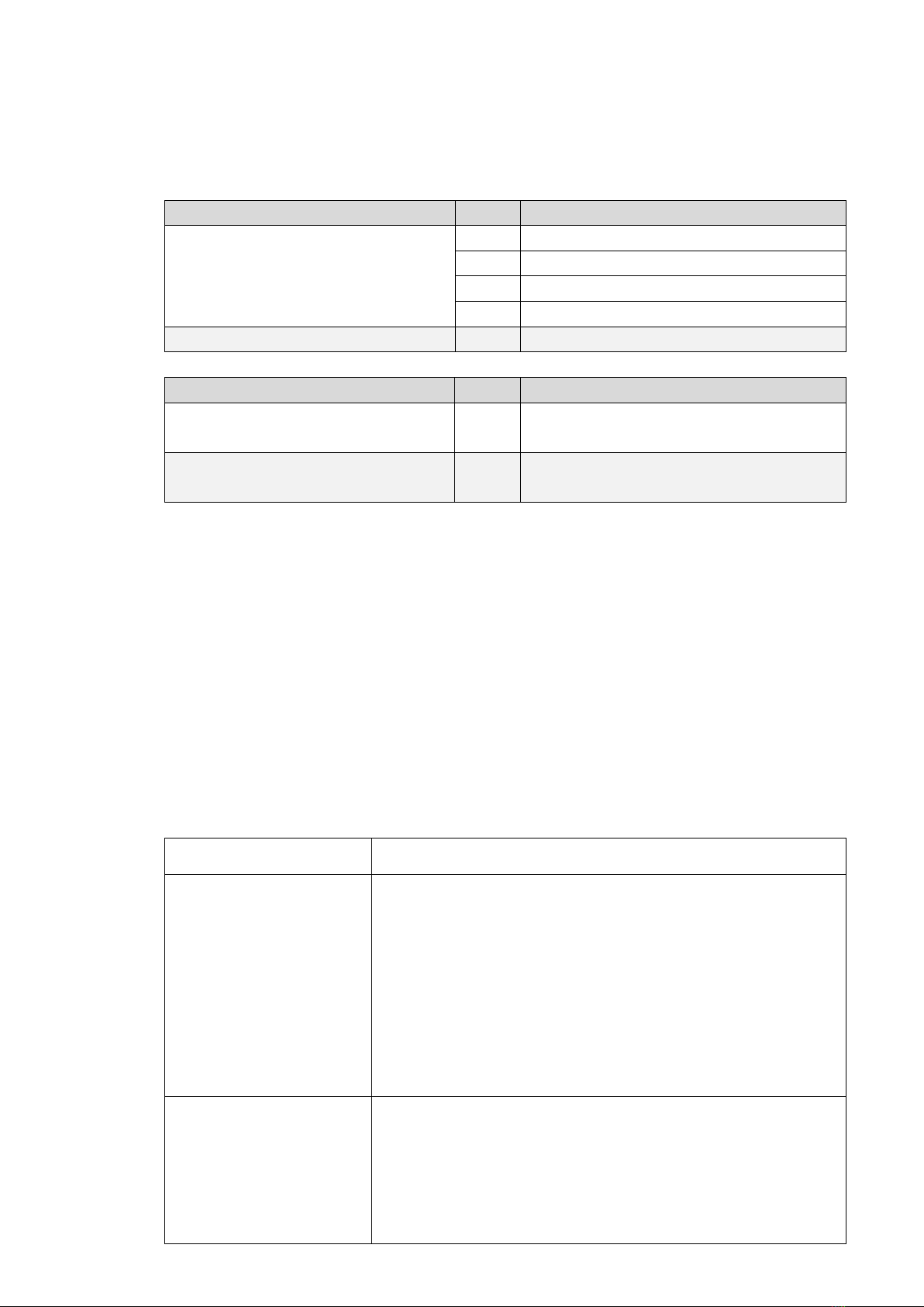
1.1 Product Applications
The CPS5000 has been designed to be suitable towards various applications, mainly due
to the fact that the product-integrated inverter is compatible by design with several
peripheral hardware components. A few applications for which the product can be
configured are described below:
Product Application
Description
UPS Application
UPS solutions are required in systems where power supplied
to the load should remain uninterrupted & stable regardless
of grid supply stability. Typically, UPS solutions are installed
in systems where inconsistent & unreliable grid-supplied
power is the only available power source. Following
installation, the product’s integrated battery/batteries
provide a secondary power source from which the supply of
energy to connected essential load devices is triggered
instantly whenever grid-supplied power is interrupted.
Daily Cycling Application
Daily cycling applications can be found in multi-component
systems that include one or more batteries. Such systems
are designed to ensure maximum usage of the installed
batteries on a regular basis. Apart from grid power, daily
cycling systems typically include the integration of
additional power sources or components required for
energy generation, such as a solar panel array, backup
generator or wind turbine. Much of the energy generated
by renewable means during the day is typically supplied to
increase battery SoC for use at night.
Off-grid Application
Off-grid systems do not make use of utility/grid power
supply. Batteries are always included in such systems. These
batteries are recharged from alternative sources such as
solar panel arrays, wind turbines and/or generators.
1.2 Requirements & Limitations
Please note that the CPS 5000-King 5.2k has been pre-configured for UPS applications.
The product is therefore not “solar-ready” but can be reconfigured for such purposes.
Please see D3. Adding Solar below. Familiarising yourself with system subcomponents
minimises the risk of failure during product installation. For non-standard applications of
the product, one or more of the product’s integrated components might have to be
reconfigured to ensure maximum application compatibility. In such cases, it is especially
important to reference the technical specifications of all relevant subcomponents –
especially the limitations of each. ensure that none of these are exceeded during
subcomponent reconfiguration.
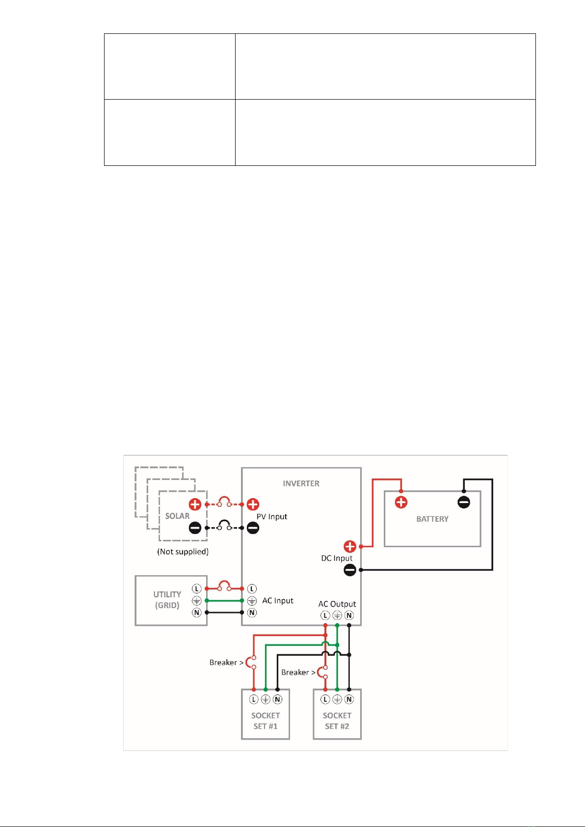
1.3 Wiring Diagram
The simplified wiring diagram below illustrates how the CPS 5000-5.2k’s components
have been connected to each other. Note that a solar panel array & connection has been
illustrated even though these components are not supplied with the product.

2. PRE-INSTALLATION: PRODUCT ASSEMBLY
The following section lists instructions for assembling the CPS5000-Vic 5.2k prior to
installation. For the purposes of this document, assembly instructions include mounting
the 2 sections of the product onto a wall. Therefore, before commencing with product
assembly, careful consideration should be taken towards where the product should be
installed.
STEP 1
Connect utility/grid supply to the inverter.
Remove the cover of DB-B. Thread a 3-core (earth, live & neutral) wire
through one of the compression glands at the bottom of the top
section, then through one of the openings available on the
distribution board. Connect the wire to the top of the breaker labelled
AC IN. The opposite open end of this wire can then be connected to
the AC supply from the site DB directly or fitted with a plug so that the
system can be charged from one of the site’s wall outlets.
STEP 2
Mount the top section backboard onto a sturdy wall.
Use a levelling tool during this step to ensure neat, level installation.
Don’t remove the inverter or any other pre-installed subcomponents
from the backboard during mounting. Use all the rawl bolts supplied.
The top section should be mounted as high as possible without
compromising access to the inverter’s user interface and/or legibility
of any information that might be displayed thereon. Typically, the top
section would be mounted at an overall height that would leave the
inverter’s UI on eye-level with a standing person of average height.
STEP 3
Mount the battery bracket below the newly-mounted top section.
The battery bracket should be installed directly below the newly-
mounted top section & vertically-centred with it. The distance
between the top section & bracket should be short enough to allow
the battery to be connected to the inverter with the cables included
for this purpose. Before mounting the bracket, check to ensure that
the bracket’s chosen location will allow for successful connection.
Space constraints & other site restrictions might require side-by-side
installation (or other non-standard orientations) of the two sections,
for which the supplied cables might be too short. In such cases, please
ensure that replacement cables comply to industry-standard
requirements & are based on the relevant max. continuous
performance specifics of the battery/battery pack and the inverter
(see G. Supporting Documents for data sheets).
STEP 4
Install the battery onto the bracket, then connect to the top section.

To connect the battery to the top section, connect the red wire to the
battery’s positive terminal & connect the black wire to the battery’s
negative terminal. The black negative wire is already connected to the
inverter directly, while the red positive wire is connected to the
inverter via the DB-A breaker labelled Battery (+)
STEP 5
Connect the load.
The load can now be connected to one or both of the socket sets
available on the top section. Please take note of the following
limitations:
-The maximum power that the inverter can supply at any given
time at 25°C is 4000W. Should this output limitation be exceeded
for more than a few seconds, the inverter will auto-disconnect.
At temperatures higher than 25°C, maximum inverter output will
derate to less than 4000W. See the inverter manual included with
shipment for more information.
-The AC breakers installed on DB-B for the 2 socket sets are rated
at 16A for each socket set. Should the total current demanded
from either socket set exceed this limitation, the associated
breaker will trip.
3. ADDING SOLAR (PV APPLICATION)
In order to connect a solar panel array to the CPS5000 system, a suitable Victron MPPT
module will have to be installed. Such installations should only be performed by qualified
electrical technicians with experience in Victron installations.
Please contact your nearest Victron-accredited installer for such installations.
Alternatively, please contact BlueNova if you would like to be referred to one or more
such installers.
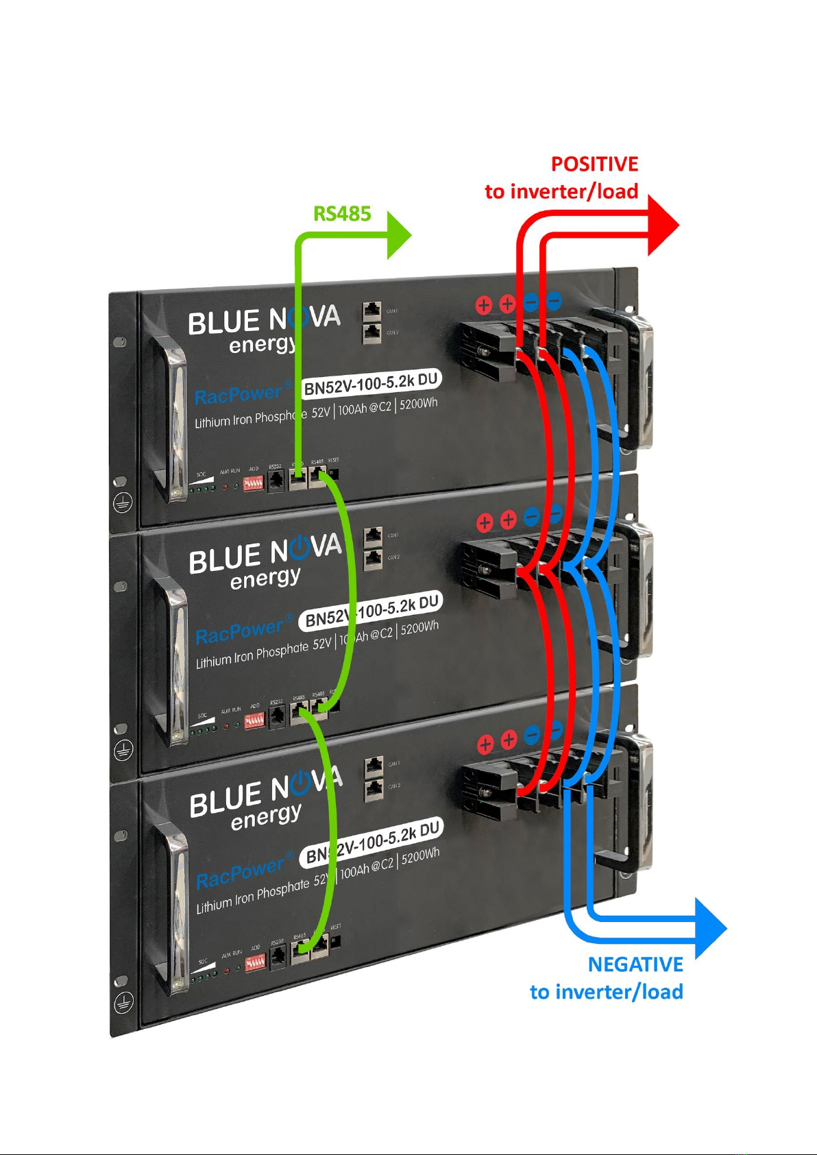
4. ADDING MORE BATTERIES
Additional batteries can be connected to the original battery to increase overall capacity.
Batteries should be connected as illustrated below:
ON
OFF
1
2
3
4
5
6
E. Battery Operation
SYSTEM START / SHUT DOWN / RESET:
FUNCTION
OPERATION
Start
Press the RESET button for 3s when the battery is in sleep mode to
switch it on. Led on the panel flashes from the Left to Right.
Shut down
Press the RESET button for 3s when the battery is in idle/discharge
mode to switch it OFF. Led on the panel flashes from Right to Left.
Resetting
Press the RESET button for 6s when the battery is in idle/discharge
mode to reset the BMS.
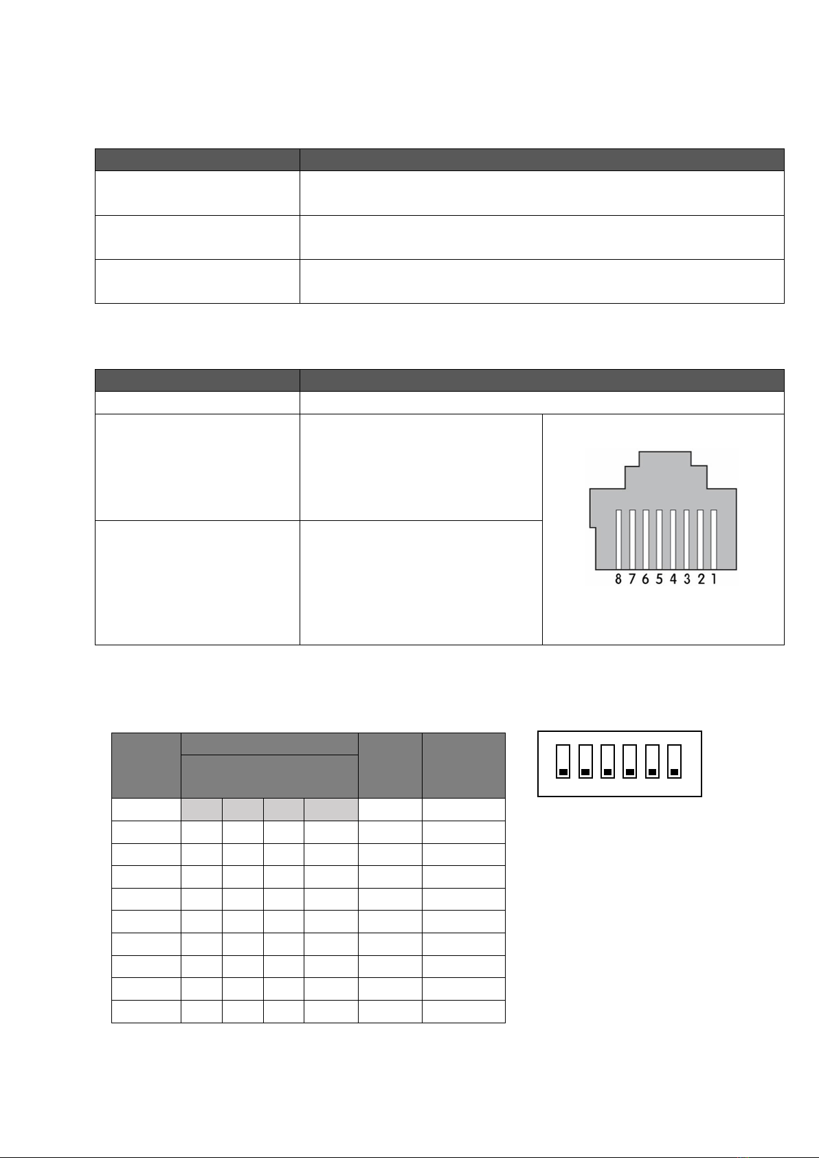
COMMUNICATION PORTS:
COMPONENT
FUNCTION / DESCRIPTION
RS232 (RJ11)
Not active
CAN Ports (RJ45 x 2)
Serial communication via CAN
Bus. PIN configuration as follows:
-7 : CAN-H
-8 : CAN-L
RS485 Ports (RJ45 x 2)
Pin configuration as follows:
-1/8 : A
-2/7 : B
-3/6 : GND
-4/5 : NC
DIP SWITCH PANEL CONFIGURATION:
Address
DIP Switch Number
Master
/ Slave
(CAN)
Definition
(RS485)
Parallel Configuration
#1
#2
#3
#4
1
ON
OFF
OFF
OFF
Master
Pack1
2
OFF
ON
OFF
OFF
Slave 1
Pack2
3
ON
ON
OFF
OFF
Slave 2
Pack3
4
OFF
OFF
ON
OFF
Slave 3
Pack4
5
ON
OFF
ON
OFF
Slave 4
Pack5
6
OFF
ON
ON
OFF
Slave 5
Pack6
7
ON
ON
ON
OFF
Slave 6
Pack7
8
OFF
OFF
OFF
ON
Slave 7
Pack8
9
ON
OFF
OFF
ON
Slave 8
Pack9
It is essential to set the DIP address number in order when connected with a CAN bus inverter,
otherwise the BMS will report an error.

STATE-OF-CHARGE:
COMPONENT
FUNCTION / DESCRIPTION
State-of-charge indicator
0% –25% SoC
25% –50% SoC
50% –75% SoC
75% –100%
SoC
LED indicators:
Status
Running
condition
SOC
RUN
ALM
Description
Switch Off
Sleep mode
off
off
off
off
off
off
All off
Stand by
Normal
off
off
off
off
Flash 1
off
Idle
Alarm
off
off
off
off
Flash 3
Flash 3
ALM and RUN Flash
3
Charging
Normal
According to real-time
capacity
on
off
Highest LED Flash 2
OV Alarm
According to real-time
capacity
on
off
Highest LED Flash 2
OC Alarm
According to real-time
capacity
on
Flash 3
Highest LED Flash 2
OV Protect
on
on
on
on
on
off
OC Protect
(charge limit
off)
off
off
off
off
off
on
Stop charging
Charge limit
According to real-time
capacity
on
off
Highest LED Flash 2
Discharging
Normal
According to real-time
capacity
Flash 3
off
According to real-
time capacity
indicate
Alarm
According to real-time
capacity
Flash 3
Flash 3
ALM and RUN Flash
3
OC/short
circuit/revere
connection
off
off
off
off
off
on
Stop discharging
UV
off
off
off
off
off
off
Stop discharging
Temp
Normal
According to status
Charge alarm
According to real-time
capacity
on
Flash 3
Highest LED Flash 2
Discharge
alarm
According to real-time
capacity
Flash 3
Flash 3
Protect
off
off
off
Off
off
on

F. Operating Instructions
1. INVERTER
Please refer to the inverter manual enclosed within the product packaging.
2. RECOVERY FROM OVER-DISCHARGE
If the batteries are over-discharge and left uncharged for a period of time, they will enter
protection mode. To recover the batteries from this mode, follow the procedure below:
-Turn off battery circuit breaker(s) on the unit’s integrated DB.
-Turn on mains supply breaker. You have to have a working mains supply.
-Wait for 2 hours, then turn on the battery breaker(s). The inverter must start and charge the
battery with a positive current at this point. Reference the integrated battery display.
-If the batteries are not charged, repeat steps 1 to 3 above.
-Should the system not start up at this point, please contact BlueNova technical support.
G. Emergency & First Aid
1. IN CASE OF FIRE
a. Evacuate danger zone. Open ventilation in the room if possible.
b. Extinguish fire with a CO2 fire extinguisher.
c. After the fire has been extinguished, immerse any remaining smoking cells completely in
water.
Wear protective gear during this procedure.
2. SKIN CONTACT
a. Wash the affected area immediately with soap and water.
b. If irritation persists, seek medical attention.
3. EYE CONTACT
a. Rinse eyes immediately with clean water continuously for at least 15 minutes.
b. Seek medical attention immediately afterwards.
4. INGESTION
a. Refrain from taking any emetic or vomit-inducing medicine.
b. Seek medical attention immediately.
This manual suits for next models
3
Table of contents
Popular Inverter manuals by other brands


ECO-WORTHY
ECO-WORTHY CSP600 user manual

Huawei
Huawei SUN2000-50KTL-ZHM3 quick start guide

Analytic Systems
Analytic Systems IPS2000 Installation & operation manual

Analytic Systems
Analytic Systems IPS600 SERIES Installation & operation manual

hpmont
hpmont HD07-S Series Simple manual

Steca
Steca AJ 275 User's and installer's manual