ABB PVI-3.0-TL-OUTD-S-US User manual

ABB solar inverters
Product manual
PVI-3.0-3.6-3.8-4.2-TL-OUTD-S-US (-A)
(3.0 to 4.2 kW)

- 2 -
3001CV
List of related manuals
UNO manuals and guides Code (English)
PVI-3.0-3.6-3.8-4.2-TL-OUTD-US
(-A) Quick Installation Guide
BCM.00161.1

- 3 -
3001CV
IMPORTANT SAFETY INSTRUCTIONS
This manual contains important safety instructions that must be followed during installation
and maintenance of the inverter.
SAVE THESE INSTRUCTIONS!
Keep this document in a safe place near the inverter for easy access during installation and
maintenance.
THE INSTALLER MUST READ THIS DOCUMENT IN ITS ENTIRETY BEFORE
INSTALLING OR COMMISSIONING THIS EQUIPMENT.
The purpose of this document is to support the qualied technician, who has received training
and/or has demonstrated skills and knowledge in construction, to install and maintain this inverter.
This manual does not cover any details concerning equipment connected to the inverter such
as the solar modules. Information concerning the connected equipment is available from the
respective manufacturers.
Warranty conditions can be found on the UNO product page of the website.
NOTE: Any changes or modications not approved by the responsible party could void the
user authority to operate the equipment.
FCC REMARKS
The equipment has been tested and found to comply with the limits for a Class B digital
device, pursuant to Part 15 of the FCC Rules. These limits are designed to provide reasonable
protection against harmful interference in a residential installation. This equipment generates,
uses and can radiate radio frequency energy and, if not installed and used in accordance with
the instructions, may cause harmful interference to radio communications.
However, there is no guarantee that interference will not occur in a particular installation. If
this equipment does cause harmful interference to radio or television reception, which can be
determined by turning the equipment off and on, the user is encouraged to try to correct the
interference by one or more of the following measures:
• Reorient or relocate the receiving antenna.
• Increase the separation between the equipment and receiver.
• Connect the equipment into an outlet on a circuit different from that to which the receiver
is connected.
• Consult the dealer or an experienced radio/TV technician for help.

- 4 -
3001CV
Product Manual
PVI-3.0/3.6/3.8/4.2 string inverters
1 - Introduction and safety
2 - Installation location
3 - Mounting and wiring
4 - Operations
5 - Troubleshooting
6 - Maintenance
7 - Appendix
PVI-3.0-3.6-3.8-4.2-TL-OUTD-S-US (-A) Product manual
BCG.00681.1_AA NA Rev 1.0
© Copyright 2014 ABB. All Rights Reserved.

- 5 -
3002TC
Contents
Introduction and safety ...................................................................................................................... 7
Warnings in this document ...................................................................................................................7
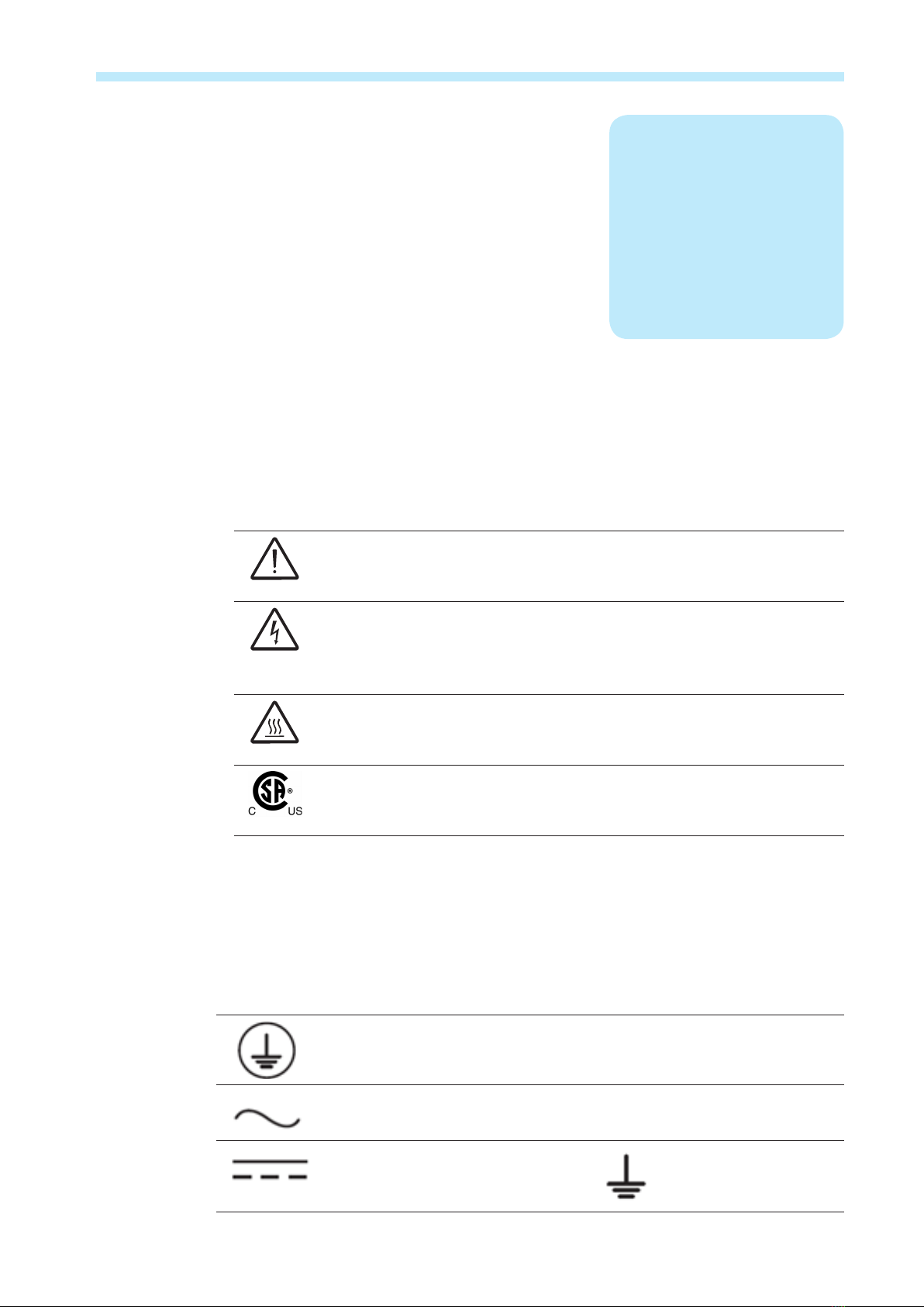
Equipment safety warnings.................................................................................................7
General installation warnings..............................................................................................8
Assembly warnings ..............................................................................................................8
Electrical connection warnings...........................................................................................8
Safety instructions .................................................................................................................................9
General information..............................................................................................................9
Thermal and voltage hazard ................................................................................................9
Clothing and protective devices .......................................................................................10
Location of safety notices and labels...............................................................................10
Appropriate usage................................................................................................................................10
Environmental conditions..................................................................................................10
Improper or prohibited use................................................................................................10
Arc fault detection (AFD) .....................................................................................................................11
Available versions ................................................................................................................................11
Regulatory label ..................................................................................................................12
Installation location .......................................................................................................................... 13
Transportation and handling...............................................................................................................13
Lifting ...................................................................................................................................13
Incoming inspection...........................................................................................................13
Select the installation location............................................................................................................14
Environmental check..........................................................................................................14
Installation position ............................................................................................................15
Mounting and wiring ....................................................................................................................... 17
Wall mounting .......................................................................................................................................17
Wiring details ........................................................................................................................................19
Wiring box components.....................................................................................................19
Wiring connections.............................................................................................................22
DC array connections ..........................................................................................................................23
Independent or parallel configuration of inputs..............................................................24
Setting the input mode switch S1 .....................................................................................25
Parallel mode front switch wiring box –S versions only without AFD .........................25
Parallel mode bottom switch wiring box and -S version with AFD...............................26
AC grid connection ..............................................................................................................................26
Serial communication (RS-485).........................................................................................29
Daisy chain multi unit configuration ................................................................................29
Addressing each inverter...................................................................................................30
Configurable relay connection (Alarm) ............................................................................31
Remote control connection ...............................................................................................31
Monitoring system via serial (RS-485)..............................................................................31

- 6 -
3002TC
Operations........................................................................................................................................ 33
Monitoring and data transmission .....................................................................................................33
Types of data available ......................................................................................................33
User interface........................................................................................................................................33
Display and keypad ............................................................................................................34
LED indicators.....................................................................................................................35
Cyclical display of general information............................................................................36
Statistics menu ...................................................................................................................37
Settings menu .....................................................................................................................38
Information menu................................................................................................................45
Commissioning.....................................................................................................................................46
Connection of system to the grid .....................................................................................46
First phase - electric parameter monitoring ....................................................................48
Troubleshooting............................................................................................................................... 49
Arc fault detection self-test errors......................................................................................................49
Obtaining the service level password................................................................................................50
Display messages and error codes ...................................................................................................50
Making a service call............................................................................................................................61
Maintenance..................................................................................................................................... 63
Routine maintenance ...........................................................................................................................63
Recommended system maintenance.................................................................................................64
Preventative maintenance...................................................................................................................64
Storage and dismantling .....................................................................................................................65
Appendix........................................................................................................................................... 67
System description .............................................................................................................................67
Protective devices within the inverter................................................................................................68
Topographic diagram of the equipment ............................................................................................68
Efficiency curves ..................................................................................................................................70
Automatic power reduction.................................................................................................................71
Technical data and types.....................................................................................................................73

- 7 -
3003CH
Warnings in this document
This is a list of special safety symbols used in this manual that highlight potential safety risks and/or useful
information. The symbol usage is described below:
CAUTION
The reader should stop, use caution and fully understand the operations
explained before proceeding.
DANGEROUS VOLTAGE
The product works with high voltages. All work on the inverter must follow
the described documentation and must comply with all prevailing codes and
regulations associated with high voltages.
HOT TEMPERATURE
Some surfaces may become hot; do not touch the product while it is in
operation.
UL1741 Standard for Safety for Inverters, Converters, Controllers and
Interconnection System Equipment for use with Distributed Energy
Resources. CSA-C22.2 No. 107.1-01 - General Use Power Supplies.
Equipment safety warnings
In addition to the safety and hazard symbols, the following symbols are also used in this
installation guide
System earth conductor (equipment ground, protective earth)
Alternating current (AC) øPhase
Direct current (DC) Grounding (earth)
1
Introduction and safety

- 8 -
3003CC1
1- Introduction and safety
General installation warnings
The ABB transformerless inverter is designed and tested according to international safety
requirements (UL1741/IEEE1547); however, certain safety precautions must be observed
when installing and operating this inverter. Read and follow all instructions, cautions and
warnings in this installation manual.
All operations regarding transport, installation start up, and maintenance, must be carried out
by qualied, trained personnel and in compliance with all prevailing local codes and regula-
tions.
Assembly warnings
Prior to installation, inspect the unit to ensure absence of any transport or handling damage,
which could affect insulation integrity or safety clearances; the failure to do so could result in
safety hazards.
Assemble the inverter per the instructions in this manual. Use care when choosing the
installation location and adhere to specied cooling requirements.
Unauthorized removal of necessary protection features, improper use, incorrect installation
or operation may lead to serious safety and shock hazards and/or equipment damage.
Electrical connection warnings
This grid-tied inverter system operates only when properly connected to the AC utility grid.
Before connecting the inverter to the AC utility grid, contact the local power distribution
company to receive the appropriate approvals. This connection must be made only by
qualied technical personnel.
Wiring methods used should be in accordance with the National Electric Code,
ANSI/NFPA 70 (NEC), Canadian Electric Code (CEC), and/or other local codes
and regulations.
WARNING: To reduce the risk of re, connect only to a circuit provided with 15A,
20A, or 25A maximum branch circuit overcurrent protection in accordance with the
National Electric Code (ANSI/NFPA 70). See Maximum AC OCPD requirement in
Appendix, section 7.
The inverter should be connected only to a dedicated branch circuit. ABB DOES
NOT provide AC output overcurrent protection; it is the responsibility of the end
user to provide protection for the AC output circuit.
Connect only to a circuit provided with the maximum branch OCPD in accordance
with the CSA document available on the website and listed in the technical data of
the appendix, section 7.

- 9 -
3003CC1
1- Introduction and safety
Safety instructions
These servicing instructions are for use by qualied personnel only. To reduce the risk of electric shock, do not
perform any servicing other than that specied in the operating instructions. Be sure all ammable materials
including construction items are away from the unit. Do not install the inverter in or near potentially explosive
areas.
The inverter is designed without an isolation transformer and is intended to be installed per NFPA 70, 690.35
with an ungrounded PV array. These models have no grounded input conductors.
General information
The equipment has been manufactured in accordance with the strictest accident-prevention
regulations and supplied with safety devices suitable for the protection of components and
operators. Inform ABB about non-standard installation conditions.
It is essential to provide operators with correct information. They must read and comply with
the technical information given in the manual and any other attached documentation. The
instructions given in the manual do not replace the information and warnings on the
safety labels mounted on the product. They do not replace the safety regulations enforced
in the country of installation.
Maintenance operations must be carried out according to the maintenance section 6 of this
manual. Do not use the equipment if any operating anomalies are found. Liabilities arising
from commercial components are delegated to their respective manufacturers.
Thermal and voltage hazard
WARNING: Depending upon ambient temperatures during operation and
immediately following shut down, surface temperatures on the cooling ns (heat
sink) and some areas of the chassis may be extremely hot to the touch.
Prior to touching any part of the inverter use care to ensure surfaces and equipment are at
touch-safe temperatures and voltages before proceeding.
The customer and/or installer must appropriately instruct all personnel who may come
near the equipment, and highlight, if necessary with notices or other means, the hazardous
areas or operations: magnetic elds, hazardous voltages, high temperatures, possibility of
discharges, generic hazard, etc.
Anytime the inverter has been disconnected from the AC utility grid, use extreme caution
as some components can retain charge sufcient to create a shock hazard and may need
time to dissipate the charge. To minimize occurrence of such conditions, comply with all
corresponding safety symbols and markings present on the unit and in this manual.

- 10 -
3003CC1
1- Introduction and safety
Clothing and protective devices
Appropriate Personal Protective Equipment (PPE) must be worn at all times when servicing
this equipment under any conditions which may subject personnel to hazardous voltages or
temperatures that are not touch-safe.
All operations on the equipment should be performed with properly electrically insulated
instruments.
Location of safety notices and labels
Note the location of safety notices on the inverter for notication and protection. Labels must
not be hidden with external objects or parts such as rags, boxes, or other such equipment.
They should be cleaned periodically and always maintained in view.
Appropriate usage
The inverter is a photovoltaic inverter that converts direct current of a connected PV array into alternating
current and feeds that power into the AC utility grid. This inverter is designed for outdoor use, but can be used
indoors if installed to specied environmental and mounting parameters stated in this manual, and adherence
to the National Electric Code. (See environmental conditions below and environmental checks in section 2.)
Conditions of Use
WARNING!
This inverter utilizes a transformerless design and requires connect-
ed array(s) to be oating with respect to ground; it can be used only with photovol-
taic modules that do not require one of the terminals to be grounded.
• The DC and AC operating currents MUST NOT exceed the limits documented in the
technical specications.
• The inverter is certied for use only with photovoltaic arrays connected to its input
channel(s). Do not connect batteries or other types of power sources.
• The inverter can only be used if all the technical requirements in this manual are observed
and applied.
Environmental conditions
Adverse environmental conditions can lead to a reduction in performance. The equipment
should be installed outdoors, but only in environmental conditions indicated in this manual.
Care must be taken to provide adequate ventilation if installed indoors.
Improper or prohibited use
The following actions are dangerous and not consistent with acceptable practice under the
terms of the warranty:

- 11 -
3003CC1
1- Introduction and safety
• Installing the equipment in environments with ammable conditions.
• Using the equipment with safety devices not working or disabled.
• Using the equipment or parts of the equipment by connecting it to other machines or
equipment, unless otherwise expressed.
• Modifying areas that are operator restricted and/or altering parts of the equipment in
order to vary the performance or change its protection.
• Cleaning with corrosive products that may corrode parts of the equipment or with products
that might generate electrostatic charges.
• Using or installing the equipment or parts of it without having read and correctly interpreted
the contents of this manual.
• Blocking airow to the cooling ns (e.g., warming or drying rags) on the unit or accessory
parts is dangerous and could compromise the inverter operation.
Arc fault detection (AFD)
The 2011 National Electric Code (NEC) and 2013 Canadian Electric Code (CEC) includes a new condition that
requires a photovoltaic system with a DC voltage greater than 80V, and which is on a building or whose DC
conductors enter a building, be equipped with a Listed device which can detect a DC arc fault and interrupt the
circuit. This functionality is commonly referred to as a DC Arc Fault Current Interruption.
The ABB DC ARC FAULT DETECTOR and INTERRUPTOR (AFDI) solution is based on Digital Signal
Processor (DSP) technology. The AFDI module has two independent channels, designed to accommodate the
two independent MPPT channels associated with all ABB String inverters, and has two current sensors and
associated circuitry to identify the presence of a series DC arc fault at the input of either inverter MPPT channel.
The DC AFDI module performs a self-test every time the system is started and the inverter display shows the
result, which can only be pass or fail. If it fails, an error code will be displayed and the inverter will not connect
to the grid. If it passes, the inverter connects and works normally.
If a DC arc fault is detected during normal operations, the inverter disconnects from the AC grid. The DC arc
fault error is indicated on the inverter display screen and lock out of inverter operation is initiated until the fault
is manually reset.
NOTE: Refer to Arc Fault Detection Self-Test Errors (-A Models Only) in section 5 for display error
messages and instructions to reset fault conditions or manually start the self-test procedure.
.
Available versions
This document applies only to the following transformerless inverter models which can be divided into two
groups according to their rated output power of 3.0 kW, 3.6 kW, 3.8kW or 4.2kW..

- 12 -
3003CC1
1- Introduction and safety
3.0 kW PVI-3.0-OUTD-US
PVI-3.0-OUTD-S-US
PVI-3.0-OUTD-S-US-A
• Unit Weight -S version: 47.3 lbs/21.3kg
• Dimensions (H x W x D) –S Version:
33.8” x 12.8” x 8.7”/
859mm x 325mm x 222mm
3.6 kW PVI-3.6-OUTD-US
PVI-3.6-OUTD-S-US
PVI-3.6-OUTD-S-US-A
3.8 kW
PVI-3.8-OUTD-S-US
PVI-3.8-OUTD-S-US-A
4.2 kW
PVI-4.2-OUTD-US
PVI-4.2-OUTD-S-US
PVI-4.2-OUTD-S-US-A
For inverters of equal output power, the difference between models is the presence of the wiring box and the
addition of Arc Fault Detection. A description of the three models can be found below.
Available versions
PVI-3.0-3.6-4.2-OUTD-US No wiring box
PVI-3.0-3.6-3.8-4.2-OUTD-S-US Wiring box with integrated DC disconnect switch
PVI-3.0-3.6-3.8-4.2-OUTD-S-US-A Wiring box with integrated DC disconnect switch and
integrated PV AFCI Type 1 device for arc fault detection (AFD)
Regulatory label
Technical data in this manual does
not supersede the data on the
labels afxed to the equipment.
The nameplate shown is afxed
to the inverter and provides the
following information:
1. Product origin
2. Model name
3. DC input data
4. AC output data
5. Certication
6. Environmental data
7. Protection
8. Adjustable parameters
UL 1741
CSA-C22.2 No. 107.1-01
C US
®
Country of Origin Italy
www.abb.com/solar
SOLAR UTILITY INTERACTIVE
TRANSFORMERLESS INVERTER
MODEL: PVI-3.0-OUTD-S-US
This device complies with Part 15 of the FCC Rules. Operation is subject to the
following two
(2) this device must accept any interference received, including interference that may
cause undesidered operation.
Nominal Input Operating Voltage
Max. Input Voltage
Range of Input Operating Voltage
Range of Input Voltage @Full Power
Max. Input Current
Max. Input ShortCircuitCurrent (P.V. Panels)
DC RATING
Nominal Output Voltage
Operating Voltage Range
Nominal Output Frequency
Operating Frequency Range
Output Power Factor
Max. Output Current
AC RATING
Max. Continuous Output Power
Max. Output Overcurrent Protection
2 x 10 A
2 x 12.5 A
360 V
600 V
90 - 580 V
200 - 530 V
60 Hz (factory preset)
59.3 ( ) - 60.5 ( ) Hz
1 2
>0.995
12 A / 14.5 A / 14.5 A (rms)
277 V~ / 240 V~ / 208 V~ 1Ø
15 A / 20 A / 20 A
3000 W @ 55°C amb.
244-304 V~/211-264 V~/183-228 V~
DC Ground Fault Detector/Interrupter is Provided
OperatingAmbient Temperature:-25to+60 °C (-13 to +140 °F), with Output PowerDerating
Type of Enclosure:NEMA 4X
For more details about product specications refer to the Instruction Manual
(
1
):
2
Adjustable from 57.0 Hz to 59.8 Hz
Adjustable from 60.2 Hz to 63.0 Hz
( ):
conditions: (1) this device may not cause harmful interference, and
1
2
3
4
5
7
8
6

- 13 -
3004CH2
Transportation and handling
Transportation of the equipment, especially by road, must be carried out by suitable ways and means for
protecting the components (in particular, the electronic components) from violent shocks, humidity, vibration,
etc. During handling, do not make any sudden or fast movements that can create dangerous swinging.
Lifting
ABB packages and protects individual components using suitable means to make their trans-
port and subsequent handling easier. Due to the weight and complexity of this equipment,
ABB recommends the process of loading and unloading of this equipment be done by an
experienced or specialized staff knowledgeable in material handling. Where indicated or
where there is a provision, eyebolts or handles can be inserted and used as lifting points. Do
not lift several units or parts of the equipment at the same time, unless otherwise indicated.
Incoming inspection
It is the customer’s responsibility to examine the condition of the unit. Upon receipt of the
inverter, please check the following:
• Inspect the shipping container for any external damage.
• Inventory the contents against the table below and verify receipt of all items.
• Use care not to discard any equipment, parts, or manuals.
• Call the delivering carrier if damage or shortage is detected.
QTY Description QTY Description
1
1
1
1
Inverter
Inverter mounting plate
Quick installation guide
Terms and conditions
1Bag containing hardware:
4 6.3 x 70 screws
4 S x 10 wall plugs
1 Red Cable AWG 10
1 Black Cable AWG 10
1 6 x 10mm machine screw
5 6mm at washer
1 Torx 20 wrench
2
Installation location

- 14 -
3005CC2
2 - Installation location
Select the installation location
WARNING!
The inverter must be installed by qualied installers and/or licensed electricians
according to the applicable local code regulations (NEC, CEC, and other).
Once physically mounted, the wiring must be carried out with the equipment disconnected from the
grid (power disconnect switch open) and the photovoltaic panels shaded or isolated.
Environmental check
• See technical data in the appendix, section 7, to check the environmental parameters to
be observed (degree of protection, temperature, humidity, altitude, etc.).
• The maximum operational ambient air temperature MUST be considered when choosing
the inverter installation location.
• Installing the inverter where operating temperatures exceed the specications will
result in power limiting. It is recommended the inverter be installed within the specied
temperature range.
• Exposure to direct sunlight will increase the operational temperature of the inverter and
may cause output power limiting. ABB recommends using a sun shade minimizing direct
sunlight when the ambient air temperature around the unit exceeds 104°F/40°C.
• Do not install in small closed spaces where air cannot circulate freely.
• Due to acoustical noise (about 50dBA at 1 m) from the inverter, do not install in rooms
where people live or where the prolonged presence of people or animals is expected.
• To avoid overheating, always make sure the ow of air around the inverter is not blocked.
• Do not install in places where gases or ammable substances may be present.
Direct sunlight use caution
Air ow restricted use caution

- 15 -
3005CC2
2 - Installation location
Installation position
When choosing the installation location and position, comply with the following conditions:
• Install on a wall or strong structure capable of bearing the weight.
• Install vertically with a maximum incline of +/- 5°. If the mounted inverter is tilted to an
angle greater than the maximum noted, heat dissipation can be inhibited, and may result
in less than expected output power.
• Install in safe place where all switch handles and controls remain easy to reach and meet
height requirements of the applicable electrical code. Install at eye level so the display
and status LEDs can be easily seen.
• Ensure sufcient working area in front of the inverter to allow removal of the covers and
easy access for servicing the inverter.
• When planning the installation, maintain clearance distances shown to allow normal
control functions and easy maintenance operations.
For multiple-inverter installations, position the inverters side-by-side, maintaining minimum
clearances. If the space available does not allow the side-by-side arrangement, multiple in-
verters can be placed in a staggered arrangement; this minimizes heat dissipation from lower
inverters affecting operation of other inverters.
Minimum clearances illustrated below include width of inverter plus additional allowances for
inverters arranged above or below.
6
in
8
in
6 in 6 in
UNO
Side-by-side arrangement
Staggered arrangement
6” 6”
25” 25”
25”

- 16 -
3005CC2
2 - Installation location

- 17 -
3006CH3
Wall mounting
The inverter should be mounted vertically as shown in section 2.
Follow the steps on the next page for mounting the inverter.
Included in the shipping package is a mounting kit with four screws
and four wall plugs provided for mounting the metal bracket to a
concrete wall. The screws should be mounted in the four holes
present in the bracket (shown as position B at right). Use two
additional screws in the two holes shown as position A if needed to
ensure stability of the inverter.
If the installation is done on a concrete wall, the wall plugs provided
should be used and the mounting holes in the wall should have
a 10mm diameter and 75mm depth. When the wall is made of a
different material (other than concrete) the installation should be
done using adequate mounting material. ABB recommends always
using stainless steel screws.
Components included in mounting kit XAK.00060.0
1 Wall bracket shown at right - 833G7424400-G
1 Hardware bag containing:
4 - 6.3 x 70mm screws, washers, and- S x 10 anchors
4 - 6 x 10mm machine screw 1 - 6mm at washer
1 - Red cable AWG10 - 9153G038600
1 - Black cable AWG10 - 9153G038700
1 - Torx 20 wrench 81510000077
2 - Terminal connectors 82000006439-G
3
Mounting and wiring

- 18 -
3007CC3
3 - Mounting and wiring
• Using the mounting bracket as
a template, locate and mark the
desired mounting location.
• Using the four screws provided,
level and mount the bracket to the
surface using mounting holes B
illustrated on previous page.
• Two additional screws can be used
if necessary.
• Orient the bracket such that the
hooks in position C face outward
and upward.
• Hang the inverter on the mounted
bracket by lifting the unit up and
over the mounting plate.
• Guide the inverter and switchbox
brackets engaging the brackets
C-D and E-F on the back of the
inverter.
• Secure chassis bottom using
the machine screw and washer
provided through center hole H on
the inverter and engaging in the
bracket G.
• Add additional screws as necessary
through bottom ange securing to
mounting surface.
165mm
188mm
80mm

- 19 -
3007CC3
3 - Mounting and wiring
Wiring details
WARNING: Always respect the nominal ratings of voltage and current dened in the
Appendix, section 7, when designing the system. Observe the following considerations in
designing the photovoltaic system:
• Maximum array DC voltage input to each MPPT circuit: 600 Vdc under any condition.
• The maximum allowable input short circuit current limit of the PV array for each MPPT
input channel is 20Adc for the 3.6kW, 3.6kW and 4.2kW inverter, and 12.5Adc for the
3.0kW.
Wiring box components
Table 3-1 switchbox external components
Ref. Description
ADC conduit entry KO’s; trade size 1”, 1-1/4”
BAC conduit entry KOs; trade size 1“, 1-1/4”
CDC disconnect switch
DSignal conduit entry with plastic threaded plug, ½: trade size
EAC conduit entry with plastic threaded plug; trade size 1”, 1-1/4”
FDC conduit entry with plastic threaded plug; trade size 1”, 1-1/4”
GSilkscreen ON/OFF legend
HWiring box front cover screws (4)
The DC switch is a four-pole device rated at 25A/contact. If operating in the parallel mode,
feed both sets of input terminals to ensure the total input current is divided between the two
sets of switch contacts to guarantee the switch current specications are not exceeded.

- 20 -
3007CC3
3 - Mounting and wiring
DC electrical schematics for front switchbox, AFD available on –A models only
1
2
3
1
2
3
GRID
GND
DC SWITCH
BOX INVERTER
+IN1
-IN1
+IN2
-IN2
DC IN
GRID
+IN1
-IN1
+IN2
-IN2
AFD
WARNING! The DC disconnect switch disconnects the DC PV panel current from
the photovoltaic panels when the switch is in “OFF” position. The inverter will stop
producing power, but it DOES NOT disconnect the AC from the grid.
To disconnect the inverter from the AC grid, an AC switch (not included in the
switchbox) must be disconnected. It is the responsibility of the installer to provide
external disconnect switches and Overcurrent Protection Devices (OCPD) as re-
quired by National Electric Codes and other prevailing regulations.
To access the wiring terminals in the inverter and switchbox, the inverter cover and switchbox
cover must be removed.
• To remove the front cover of the inverter compartment, loosen the four captive screws
indicated using the Torx screwdriver provided.
• To remove the front cover of the switchbox, loosen the four captive screws indicated
using the Torx screwdriver provided in the box with the inverter.
• When connection operations are complete and the unit is connected, replace the covers
and tighten the cover screws with at least 1.5Nm (13.2 in-lbs) torque to maintain proper
waterproof sealing.
This manual suits for next models
7
Table of contents
Other ABB Inverter manuals

ABB
ABB UNO-2.0-I-OUTD User manual

ABB
ABB REACT-3.6-TL User manual

ABB
ABB UNO-2.0-I-OUTD-US User manual

ABB
ABB REACT 2 Series User manual

ABB
ABB PVI-3.8/4.6-I-OUTD User manual

ABB
ABB EMIU 1500W User manual

ABB
ABB PVS-60-TL-US User manual

ABB
ABB TRIO-50.0-TL-OUTD-US User manual

ABB
ABB PVS980-58 Use and care manual

ABB
ABB PVS-100 Series User manual

ABB
ABB PVI-GSM/GPRS User manual

ABB
ABB UNO-2.0-TL-OUTD User manual

ABB
ABB TRIO-50.0 User manual

ABB
ABB PVI-5000-TL-OUTD User manual

ABB
ABB PVS-175-TL Series User manual

ABB
ABB UNO-2.5-I-OUTD User manual

ABB
ABB PVS-120-TL User manual

ABB
ABB Thomas & Betts 300W User manual

ABB
ABB ESI-S General instructions

ABB
ABB UNO-DM-TL-PLUS-US User manual