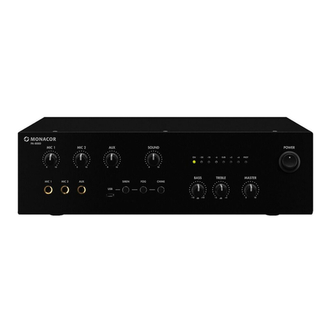
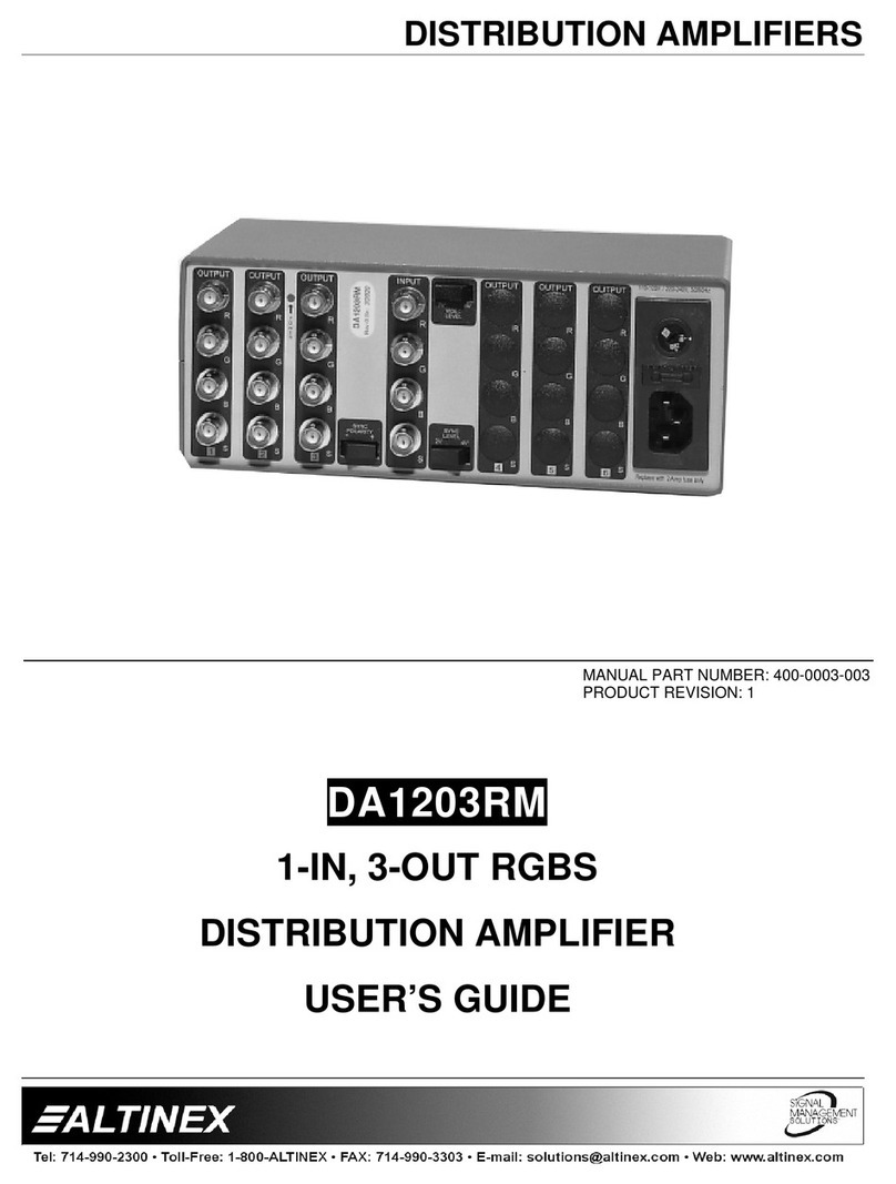
Blueprint BP TECHNOLOGY UPC120 User manual

BPTECHNOLOGY
BPTECHNOLOGY
BPTECHNOLOGY
Amplificatore singolo & doppio canale 120 W - 240 W - 500 W
Amplifier single & double channel 120 W - 240 W - 500 W
Manuale d’uso UPC120 - 240 - 500 - UPC2120 - 2240 - 2500
GENERALITÀ
Gli amplificatori di potenza monofonici sono stati progettati per appli-
cazioni generali nel campo della sonorizzazione civile.
L’ingresso bilanciato elettronicamente, su connettore XLR, il controllo
di volume montato posteriormente e i tre indicatori di stato (On, CLIP
e PROTECTION), collocano l’apparecchio ad un livello professionale.
Il sistema di raffreddamento è a dissipazione naturale e forzata con
ventola a velocità variabile.
L’uscita audio di potenza per altoparlanti (con connettore professiona-
le a doppio blocco) è prevista per il collegamento a linea ad impedenza
costante (4 ohm) o a tensione costante (50, 70 o 100 V).
La circuitazione elettronica dell’insieme ha caratteristiche di qualità e
sicurezza nel funzionamento continuo.
La carpenteria metallica è idonea all’appoggio con piedini in dotazio-
ne o inserita in armadio rack standard grazie al pannello portante a
19”. Le altezze (in unità modulari) dipendono dal modello 2 UM per
l’UPC120, UPC240, UPC2120 e per l’UPC2240 e 3 UM per UPC500 e
per l’UPC2500.
ALIMENTAZIONE
Gli apparecchi sono previsti per il funzionamento con la rete di distri-
buzione a 230 Vca - 50/60 Hz.
In caso di non funzionamento all’accensione, controllare il fusibile di
protezione esterno, ed eventualmente sostituirlo con un altro della
medesima calibratura; se il fusibile si fulmina subito, non insistere e far
controllare l’apparecchio ad un laboratorio specializzato.
Togliere sempre la spina dalla presa d’erogazione di energia elettrica
230 Vca prima di estrarre il fusibile.
LINEE AD IMPEDENZA COSTANTE
Vanno utilizzati i morsetti contrassegnati con COM e 4 Ohm.
Occorre essere sicuri del valore effettivo dell’impedenza della linea che
si sta connettendo per cautelarsi dal cattivo funzionamento dell’ampli-
ficatore e garantire la massima efficienza dell’impianto; l’impedenza
totale del sistema di diffusori deve essere uguale o più alta del valore
prescelto per il collegamento.
Per ottenere ciò, ogni altoparlante deve essere senza trasformatore e
va collegato in “serie” oppure in gruppi “serie-parallelo”; in ogni caso
gli altoparlanti devono avere anche la stessa potenza.
Owner’s manual UPC120 - 240 - 500 - UPC2120 - 2240 - 2500
ON
CLIP
PROT
TECHNOLOGY
UPC120
Amplifier 120W
BP
MAIN FEATURES
Monophonic power units have been designed for general applications
in the civic sound recording field.
The electronically balanced input (on XLR connector), the volume con-
trol (assembled in the back), the three status indicators (On, CLIP and
PROTECTION) and the highly professional circuit make the unit of a
professional level.
The dissipation cooling system is natural or forced with variable speed
fan, started by a thermic sensor.
Loudspeaker audio power outputs (with professional double block
connector) are arranged for connection with constant impedance (4
ohm) or constant voltage (50, 70 or 100 V) lines.
The whole electronic circulation has quality and safety features when
working.
The metal framing is suitable to be supported, (supports included), or
assembled in a standard rack cabinet with a 19” supporting panel. The
heights (in modular units) depend on 2U model for UPC120 and for
UPC240 and on 3 UM for UPC500.
POWER SUPPLY
The units work with a 230 Vca - 50/60 Hz distribution system.
In case of power malfunction, check the outside protection fuse and,
if necessary, replace it with one of the same calibration. If the fuse
burns out immediately, do not take any further steps and have the
unit checked by qualified personnel.
Always unplug the 230 Vca electric power socket before removing
fuse.
CONSTANT IMPEDANCE LINES
COM and 4 Ohm terminals are to be used.In order to achieve the
maximum efficiency of the system and to take precautions against
amplifier bad working, it is necessary to check the effective loading
impedance of the line. The total speakers impedance is to be equal to
or higher than the pre-selected value for connection.To get that, every
loudspeaker must be without transformer and is to be connected in
“series” or in “series-parallel” groups. In any case, loudspeakers must
also have the same power handling capability.
Blueprint S.r.l. Via Bergamo 15 24030 Medolago (BG) Tel 035-4933323 Fax 035-4933386 E-MAIL [email protected] http://www.blueprintitalia.it

BPTECHNOLOGY
BPTECHNOLOGY
Fronte UPC120 - UPC500 - Front UPC120 - UPC500
Pag. 2
LINEE A TENSIONE COSTANTE
Vanno utilizzati i morsetti contrassegnati COM, 50 V, 70 V, 100 V,
con ogni altoparlante provvisto di trasformatore di linea e collegato
in parallelo.
Per cautelarsi dal cattivo funzionamento dell’amplificatore e per garan-
tire la massima efficienza dell’impianto, occorre che la potenza totale
del sistema di diffusori sia uguale od inferiore al valore di potenza RMS
dell’amplificatore, che si sta utilizzando; si ritiene buona norma preve-
dere per l’amplificatore un margine di sicurezza del 10/20 % (quindi
una potenza maggiore).
CONSTANT VOLTAGE LINES
COM, 50 V, 70 V and 100 V terminals are to be used with every loud-
speaker provided with line transformer and parallel connected.
In order to achieve the maximum efficiency of the system and to take
precautions against amplifier bad working,
it is necessary to check that the effective total power handling of the
loudspeakers is equal to or lower than the RMS power value of used
amplifier. It’s a good rule arranging a 10-20% safety margin for the
amplifier (i.e. a superior power capability).
1. Led segnalazione accensione
2. Led segnalazione CLIP segnale ingresso
3. Led segnalazione protezione
3
2
1
CLIP
PROT
TECHNOLOGY
Amplifier 120W
BP
ON
UPC120
CLIP
PROT
TECHNOLOGY
Amplifier 500W
ON
BP
UPC500
3
2
11. Power ON indication
2. CLIP indication
3. PROTECTION indicator
INPUT
RISK OF ELECTRIC SCHOK
DO NOT OPEN
CAUTION
230 Vca 50-60Hz
FUSE T4AL250V
S/N:
TO REDUCE THE RISK OF FIRE OR
ELECTRIC SCHOCK DO NOT EXPOSE
THIS EQUIPMENT TO RAIN OR
MOISTURE
WARNING!
OFF
POWER
ON
21
XLRBAL
INPUT
1-GND
2-HOT+
3-COLD-
0
10
3
9
8
7
6
5
4
3
2
1
VOLUME
100V
POWER OUT
70V
COM
4
50V
5 6 784 9 10
4. Presa per alimentazione 230 Vca
5. Fusibile di protezione Vca
6. Interruttore accensione
7. Ingresso XLR bilanciato
8. Regolatore di volume
9. Uscita linea altoparlanti
10. Uscita ventilazione
XLRBAL
INPUT
1-GND
2-HOT+
3-COLD-
12 3
230 Vca 50-60Hz
FUSE T4AL250V
OFF
ON
RISK OF ELECTRIC SCHOK
DO NOT OPEN
TO REDUCE THE RISK OF FIRE OR
ELECTRIC SCHOCK DO NOT EXPOSE
THIS EQUIPMENT TO RAIN OR
MOISTURE
100V
70V
COM
4
50V
POWER OUT
CAUTION
WARNING!
64
0
10
82
91
73
5
VOLUME
S/N:
POWER
INPUT
5 6 7
8
4 9 10
Retro UPC120 - UPC500 - Rear UPC120 - UPC500
4. Supply socket 230 Vca
5. Main protection fuse
6. Power switch
7. Line input XLR
8. Volume control
9. Loudspeaker line output
10. Fanner

BPTECHNOLOGY
BPTECHNOLOGY
Pag. 3
1. Led segnalazione accensione canale 1
2. Led segnalazione CLIP segnale ingresso canale 1
3. Led segnalazione protezione canale 1
4. Led segnalazione accensione canale 2
5. Led segnalazione CLIP segnale ingresso canale 2
6. Led segnalazione protezione canale 2
Fronte UPC2120 - UPC2240 Front UPC2120 - UPC2500
CLIP
PROT
ON
TECHNOLOGY
Amplifier 2X120W
UPC2120
BP
CLIPON
PROT
3
2
1 4
5
6
25
CLIP
PROT
ON
TECHNOLOGY
Amplifier 2X500W
CLIPON
PROT
BP
UPC2500
3 1 4 6
1. Power ON indication channel 1
2. CLIP indication channel 1
3. PROTECTION indicator channel 1
4. Power ON indication channel 2
5. CLIP indication channel 2
6. PROTECTION indicator channel 2
Retro UPC2120 - UPC2240 Rear UPC2120 - UPC2500
VOL. 2
0
INPUT 2
2
1
3
4
10
8
9
7
6
5
0
10
INPUT 1
82
91
7
6
5
4
3
VOL. 1
3
21
XLRBAL
INPUT
1-GND
2-HOT+
3-COLD-
S/N:
230 Vca 50-60Hz
FUSE T4AL250V
POWER OUT 2
100V
70V
50V
4
COM
RISK OF ELECTRIC SCHOK
DO NOT OPEN
CAUTION
POWER
ON
OFF
TO REDUCE THE RISK OF FIRE OR
ELECTRIC SCHOCK DO NOT EXPOSE
THIS EQUIPMENT TO RAIN OR
MOISTURE
WARNING!
100V
70V
50V
4
COM
POWER OUT 1
567
8
412 131113 9
10
WARNING!
TO REDUCE THE RISK OF FIRE OR
ELECTRIC SCHOCK DO NOT EXPOSE
THIS EQUIPMENT TO RAIN OR
MOISTURE
CAUTION
RISK OF ELECTRIC SCHOK
DO NOT OPEN
230 Vca 50-60Hz
FUSE T4AL250V
100V
70V
50V
4
COM
OFF
ON
POWER
XLRBAL
INPUT
1-GND
2-HOT+
3-COLD-
INPUT 2
POWER OUT 2
S/N:
3
21
100V
70V
50V
4
COM
28 82
INPUT 1
POWER OUT 1
0
1
10
90
10
91
VOL. 2
5
3
4
7
6
7
6
5
4
3
VOL. 1
5 6 8 74 9 1310 1113 12
4. Presa per alimentazione 230 Vca
5. Fusibile di protezione Vca
6. Interruttore accensione
7. Ingresso XLR bilanciato canale 1
8. Regolatore di volume canale 1
9. Uscita linea altoparlanti canale 1
10. Ingresso XLR bilanciato canale 2
11. Regolatore di volume canale 2
12. Uscita linea altoparlanti canale 2
13. Uscita ventilazione
4. Supply socket 230 Vca
5. Main protection fuse
6. Power switch
7. Line imput XLR channel 1
8. Volume control channel 1
9. Loudspeaker line output channel 1
10. Line imput XLR channel 2
11. Volume control channel 2
12. Loudspeaker line output channel 2
13. Fanner

BPTECHNOLOGY
BPTECHNOLOGY
Pag. 4
Connessione ingresso XLR - Input connection XLR
1=MASSA - GND
2=CALDO - HOT
3=FREDDO - COLD
231
Collegamento altoparlanti impedenza (4 ohm)
Loudspeakers connection impedance (4 ohm)
Collegamento altoparlanti tensione 100 V
Loudspeakers connection voltage (100 V)
POWER OUT
70V
50V
COM
4
100V
4 ohm
4 ohm 4 ohm
4 ohm
POWER OUT
70V
50V
COM
4
100V
Modello UPC120 UPC240 UPC500 UPC2120 UPC2240 UPC2500 Model
Tensione di alimentazione 230 Vca - 24 Vcc Power supply
Consumo 220 VA 440 VA 880 VA 220 VA 440 VA 880 VA Power comsumption
Potenza uscita (RMS) 2x120 W 2x240 W 2x500 W Power output (RMS)
Uscita
Impedenza costante
4 ohm Impedence output
Uscita tensione costante 50 - 70 - 100 V Voltage output
Sensibilità ingresso 0 dB = 775 mV Input sensivity
Risposta in frequenza
50
÷ 15.000 Hz Frequency response
Distorsione
<1 %
THD
Dimensioni (L x H x P) mm
482 x 88 x 338 482 x 132 x 433 482 x 88 x 338 482 x 132 x 433
Dimension (L x H x P) mm
Peso 10,6 Kg 13,1 Kg 22,5 Kg 10,6 Kg 13,1 Kg 22,5 Kg Wight
