BlueSky Mast AL1 STANDARD Series User manual

Page 1
AL1 / AL2 Standard Series User Manual
Primary and Secondary Guying (2 - 15 Meters)
Rev. 02/2016
REV 06/2016

AL1 / AL2 Standard Series User Manual
www.BlueSkyMast.com
877-411-6278
Page 2
TABLE OF CONTENTS
Limited Twelve (12) Month Warranty………………………….…………………………………………….4
Important Safety Precautions……...………………….…………………............………………………5-7
1. Part I: Power Lines, Lightning and Grounding....................................................................5
2. Part II: Guy Ropes and Fasteners....................................................................................6
3. Part III: Wind Conditions................................................................................................7
4. Wind Conditions Reference Chart.....................................................................................7
Understanding Deployment Load and Guying................................................................8-25
1. Deployable Load............................................................................................................8
2. Wind Effects & Guying....................................................................................................9
3. Anchor Radius...............................................................................................................10
4. Primary and Secondary Guy Placement.............................................................................11
5. Guying Distance............................................................................................................11
6. AL1 Load Tables.......................................................................................................12-18
7. AL2 Load Tables.......................................................................................................19-25
Basic Component Overview............................…………………………………………………………..26
Step by Step Deployment Instructions………………......................................................27-61
1. Deploying the Standard Mast with Primary Guying Only (Models 2 to 10 Meters Only)......27-39
2. Deploying the Standard Mast with Primary & Secondary Guying (Models 2 to 15 Meters)...40-53
Deploying the Surface Wire Grounding Kit.......................................................................56
Deploying the with the Lift Handles.................................................................................57
Datasheets for AL1 and AL2 Standard Series 15M Mast…….........................................54-55
Surface Wire Grounding Deployment Instructions…………………………………………….………56
Lift Handle Instructions………………………………………………………………………………………...57
Accessory Reference Guide.........................................................................................58-75

AL1 / AL2 Standard Series User Manual
Page 3
DISCLAIMER OF WARRANTIES AND LIABILITY
DO NOT ATTEMPT TO DEPLOY THIS MAST IF YOU ARE NOT EXPERIENCED IN SIMILAR DEVICES
You are responsible for your own safety and survival and that of those persons around the mast.
This manual is to be used as an aid and only to be used at your own risk. Nothing will replace good
sound judgment when deploying the mast.
The information provided in this manual should be used as a guideline and not absolute fact. Many
variables are involved in deploying a mast system such as weather, soil conditions, guying distanc-
es, cantilevered payloads, surrounding obstacles, accuracy and precision of guying, etc.
BLUESKY MAST, INC. MAKES NO WARRANTIES REGARDING THE GOODS, EXPRESS OR IMPLIED,
INCLUDING WARRANTY OF MERCHANTABILITY OR WARRANTY OF FITNESS FOR A PARTICULAR
PURPOSE. BUYER MAKES NO RELIANCE ON ANY REPRESENTATION OR DOCUMENTATION OF
BLUESKY MAST, INC. , EXPRESS OR IMPLIED, WITH REGARD TO THE GOODS .
BLUESKY MAST, INC. SELLS THE GOODS TO BUYER ON CONDITION THAT BLUESKY MAST, INC.
WILL HAVE NO LIABILITY OF ANY KIND AS A RESULT OF THE SALE. BUYER AGREES THAT BLUESKY
MAST, INC. SHALL HAVE NO LIABILITY FOR DAMAGES OF ANY KIND, WHETHER DIRECT, INCI-
DENTAL OR CONSEQUENTIAL DAMAGES, INCLUDING INJURIES OR DEATH TO PERSONS OR PROP-
ERTY, TO BUYER, ITS EMPLOYEES, CUSTOMERS OR AGENTS, AS A RESULT OF THE SALE. BUYER
ALSO AGREES TO HOLD BLUESKY MAST, INC. HARMLESS FROM ANY CLAIMS BUYER, OR ANY
THIRD PARTY, MAY HAVE AS A RESULT OF BUYER’S USE OF THE GOODS.
BUYER HAS READ THIS DISCLAIMER AND AGREES WITH ITS TERMS IN CONSIDERATION OF RE-
CEIVING THE GOODS.
REPORTING ERRORS AND RECOMMENDING IMPROVEMENTS
If you find any mistakes or you can help improve this material, please contact BlueSky Mast via US
Mail at:
BlueSky Mast Inc Phone: 877-411-6278
1515 Gunn Hwy Or International: 718-802-3266
Odessa, FL 33556 Fax: 866-411-6278
USA email: [email protected]
Cage Code: 3JWX5 DUNS Number: 137469404
We will send you a reply concerning incorporating your suggestions. Thank You.
AL1 / AL2 Standard Series User Manual
www.BlueSkyMast.com
877-411-6278
Page 4
Limited Twelve (12) Month Warranty
This BLUESKY MAST, INC. equipment is warranted to be free from defects in material and workman-
ship under normal use and service. BLUESKY MAST, INC. shall repair or replace defective equip-
ment, at no charge, or at its option, refund the purchase price, if the equipment is returned to
BLUESKY MAST,INC. not more than twelve (12) months after shipment. Removal or reinstallation of
equipment and its transportation shall not be at the cost of BLUESKY MAST, INC. except BLUESKY
MAST, INC. shall return repaired or replaced equipment freight prepaid to a continental United
States address.
This Warranty shall not apply to equipment which has been repaired or altered in any way so as to
affect its stability or durability, or which has been subject to misuse, negligence or accident. This
Warranty does not cover equipment which has been impaired by severe weather conditions such as
excessive wind, ice, storms, lightning, or other natural occurrences over which BLUESKY MAST, INC.
has no control, and this Warranty shall not apply to equipment which has been operated or installed
other than in accordance with the instructions furnished by BLUESKY MAST, INC.
Products are manufactured from anodized aluminum in various colors. Color fading and varying
shades of color will inevitably occur with exposure to sunlight and environmental conditions and is
not considered a defect in the material or product.
Claimants under this Warranty shall present their claims along with the defective equipment to
BLUESKY MAST, INC. immediately upon failure.
Noncompliance with any part of this claim procedure may invalidate this warranty in whole or in
part.
This warranty is expressly in lieu of all other agreements and warranties, any implied warranty of
merchantability or fitness for a particular purpose is limited in duration to the duration of this war-
ranty. BLUESKY MAST, INC. Neither assumes nor authorizes any representative or other person to
assume for it any other liability in connection with the equipment delivered or provided. In no event
shall BLUESKY MAST, INC. Be liable for any loss of profits, loss of use, interruption of business, or
indirect, special or consequential damages of any kind.
In no event shall BLUESKY MAST, INC. be liable for damages in an amount greater than the pur-
chase price of the equipment. Some states do not allow limitations on how long an implied warranty
lasts, or allow the exclusion or limitation of incidental or consequential damages, so the above limi-
tations or exclusions may not apply to you.

Safety Precautions
Page 5
ImportantSafetyPrecautions
Part I: Power Lines, Lightning and Grounding
LOOK UP AND LIVE! Before erecting the mast, check for overhead power lines. Never de-
ploy this mast where there is any possibility of direct or indirect contact with a power line.
Keep the mast a distance equal to or greater than twice its height away from power lines.
This will ensure that the Antenna, masts, guy ropes or cables will not contact power if it
falls either during installation or later. Any person touching any part of a mast or even
standing near a mast that contacts a power line can be seriously injured or killed.
BEWARE OF UNDERGROUND POWER LINES! Ground stakes might penetrate underground
power lines. Before deploying any ground stakes, be sure to check the area for warnings
of buried cables and contact your local power company to verify. Any person touching any
part of a mast or even standing near a mast that contacts a power line can be seriously
injured or killed.
Keep guy ropes away from power lines to eliminate the possibility of a power line falling
on the guy rope.
Never touch a mast or structure that you suspect may be accidentally energized electri-
cally.
Never work with a mast or related structure during electrical storm activity.
Contrary to popular belief, most lightning injuries and damage do not come from direct
lightning strikes. There are several ways that lightning can injure you:
“Step Potential” is potentially hazardous voltage that can exist on the ground like
stepping on a live wire. This results from electrical energy diverted into the ground
from lightning striking nearby. It is the most common injury causing lightning ef-
fect.
Flashover is when lightning strikes a nearby object and then jumps to another
nearby object. This is usually what injures people standing under trees in an elec-
trical storm.
Do not stand near the mast, deploy or retract the mast during electrical storm activity.
Always ground the mast.

Safety Precautions
www.BlueSkyMast.com
877-411-6278
Page 6
ImportantSafetyPrecautions
Part II: Guy Ropes and Fasteners
Inspect all guy ropes and fasteners for wear or damage before use. Serious injury or death
may occur if a guy rope failure causes a mast to fall.
Mark guy ropes clearly to prevent personnel from tripping over them. Personnel who trip may
suffer injury and may also pull up a guy rope and cause the mast to fall.
Monitor the tension of the guy ropes to ensure proper tension.
Ensure that stakes and anchors are secure in the ground before attaching guy ropes. Use ex-
tra caution when anchoring guy ropes, especially in sandy or loose soil.
Never fasten a guy rope over a sharp edge or in a manner that causes abrasion. This may
cause guy rope failure. Pad any contacting surfaces if necessary.
Do not install guy ropes across roadways or other paths of travel. Always clearly mark guy
ropes.
Ensure guy ropes are clear of branches and other obstructions.
Use only authorized parts. Unapproved substitutes may not be strong enough for the equip-
ment.
Periodically inspect the mast to ensure that it remains structurally sound and properly in-
stalled.
Never overload the mast or structure. Use ONLY the equipment and accessories in proper
quantities as described by the manufacture specifications. Do not use unauthorized equip-
ment or modifications.
BE CAUTIOUS of ice that may form on the antenna/mast. The area around the antenna/mast
should be marked and roped off to avoid falling ice. Special care must be taken when retract-
ing the mast or structure to avoid falling ice.
Use additional guy ropes for the mast, if heavy ice loading or wind is expected or anticipated.
Ensure that the wind speed is not excessive during deployment/retraction operations. Maxi-
mum safe wind speeds are available from manufacturer for your specific mast.

Safety Precautions
Page 7
ImportantSafetyPrecautions
Part III: Wind Conditions
BlueSky Mast recommends that you do not to attempt to actively deploy in winds that exceed
15 mph.
During windy conditions it will be necessary to incrementally guy the mast as it is being de-
ployed.
Incremental Guying will add time to the deployment but increase the protection of personnel
and equipment.
Use this chart to determine approximate wind speed:
VISUAL
OBSERVATIONS KM/H MPH DEPLOYMENT
CONDITIONS
Smoke Rises Vertically <1 <1 Safe
Wind Direction Shown
by Smoke 1-6 1-3 Safe
Wind Felt on Face,
Leaves Rustle 7-12 4-7 Safe
Leaves & Twigs in
Constant Motion, Wind
Extends Light Flag
13-18 8-11 Use Caution
Dust and Loose Paper
Blown Freely, Small
Branched Move
19-26 12-15 Use Caution
Small Trees Begin to
Sway 27-35 16-22 Dangerous
Conditions
Large Branches in Mo-
tion, Wind Whistles
Through Wires
36-44 23-27 Dangerous
Conditions
Whole Trees in Motion 45-55 28-34 Dangerous
Conditions

Payload Capacity - Wind Load - Anchor Radius
www.BlueSkyMast.com
877-411-6278
Page 8
Deployable Payload
A mast installation can be exposed to several types of loads. The physical weight of the instrument
and its attachments is referred to as the payload. The mast can support much more weight when
properly guyed and stabilized but BlueSky Masts will only recommend payloads that are safe to car-
ry during the deployment process and we call this the deployable load. The remaining reserve load
capacity represents the margin designed to absorb any subsequent environmental load that the
mast may encounter. The primary environmental load on a mast is wind load.
The payload capacity on a BlueSky Mast is governed by the installer’s ability to safely elevate the
payload to the desired height. As poles are inserted into the tripod and the mast begins to climb,
the mast tip has a tendency to lean off-center and away from its position of greatest strength. An
iterative process of incremental guying and mast pole elevation may be required to successfully de-
ploy the mast. For best results, please limit your deployment to the height and payload combina-
tions given in the table below.
Mast Model Height (ft.) AL2
Deployable Load
(lbs.)
2 Meter 7.5 ft. 100
3 Meter 10.5 ft. 85
4 Meter 13.5 ft. 70
5 Meter 16.5 ft. 65
6 Meter 19.5 ft. 60
7 Meter 22.5 ft. 57.5
8 Meter 25.5 ft. 55
9 Meter 28.5 ft. 52.5
10 Meter 31.5 ft. 50
11 Meter 34.5 ft. 40
12 Meter 37.5 ft. 35
13 Meter 40.5 ft. 30
14 Meter 43.5 ft. 25
15 Meter 46.5 ft. 20
AL1
Deployable Load
(lbs.)
50
47.5
45
42.5
40
37.5
35
32.5
30
25
20
15
12.5
10

Payload Capacity - Wind Load - Anchor Radius
Page 9
Guying
Guy lines are used to maintain the position of the top of the mast directly over the center of the tri-
pod. This is its position of greatest strength, which will maximize the load carrying capacity of the
mast in terms of payload as well as wind survivability. When no wind is present, the guy lines re-
main critical to stabilize the top of the mast and to keep the instrument mounts level.
Wind Effects
When wind blows on a mast and its instruments, the guys restrict the top of the mast and its instru-
ments from moving off center. The mast’s reaction to wind will put tension in the guy line and force
the top of the mast downward in compression, the amount of which will vary depending on the an-
chor distance as described below.
The size and shape of the instruments determine the amount of force they produce in any given
wind condition. Don’t forget that the mast itself is a surface area exposed to the wind and its wind
load will need to be added to the instrument wind load to get the total wind load on the system. The
mast wind loads are given in the table at the end of this section and clearly show the benefits of
Secondary Guying.
Payload Capacity - Wind Load - Anchor Radius
www.BlueSkyMast.com
877-411-6278
Page 10
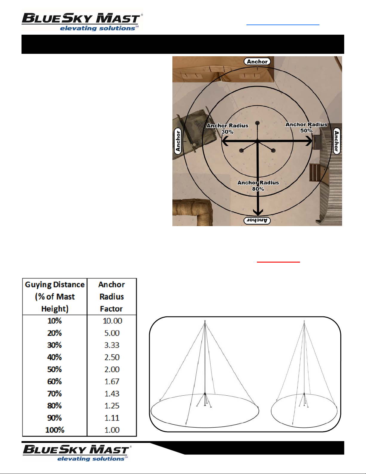
Anchor Radius
Ideal guying is set with an anchor radius of
80% of the mast height. Many applications
of mast deployments are not able to afford
an installation footprint of this size and
installers may find it more convenient to
place the guy anchors much closer to the
mast as shown in the figure to the right.
BlueSky Mast does not recommend configu-
rations utilizing less than 80% guy radius,
but if your site dictates that you must devi-
ate from the recommended configuration it
is imperative that the installer is aware of
the effects of the reduced anchor radius
and its effect on total payload capacity and
wind loading.
The angle of pull on the guy line relative to the anchor radius may produce a lever ef-
fect increasing the mast compression due to wind loading by a factor of 5 !
The table at left shows the affect the anchor radius has on the
multiplying factors of compressive loads produced on the mast
by a horizontal wind force. Below are examples of various
anchor radii.
80% 30%
Payload Capacity - Wind Load - Anchor Radius
Page 11
Model
Height
80% 50% 30%
2 M 6 ft 3.75 ft 2.25 ft
3 M 8.4 ft 5.25 ft 3.15 ft
4 M 10.8 ft 6.75 ft 4.05 ft
5 M 13.2 ft 8.25 ft 4.95 ft
6 M 15.6 ft 9.75 ft 5.85 ft
7 M 17.2 ft 10.75 ft 6.45 ft
8 M 20.4 ft 12.75 ft 7.65 ft
9 M 22.8 ft 14.25 ft 8.55 ft
10 M 25.2 ft 15.75 ft 9.45 ft
11 M 27.6 ft 17.25 ft 10.35 ft
12 M 30 ft 18.75 ft 11.25 ft
13 M 32.4 ft 20.25 ft 12.15 ft
14 M 34.8 ft 21.75 ft 13.05 ft
15 M 37.2 ft 23.25 ft 13.95 ft
% Anchor Radius /
Distance of the Guys from the
Base of the Mast
Guying Distance from Base of Mast
Use the chart to the right as reference to
determine the proper distance to place the
guy stake for the guys from the base of the
mast.
If you are unable to utilize the 80% rule
then refer to the load characteristics of your
mast in the tables following this section to
understand the impact to the payload
capacity and wind loading of your mast.
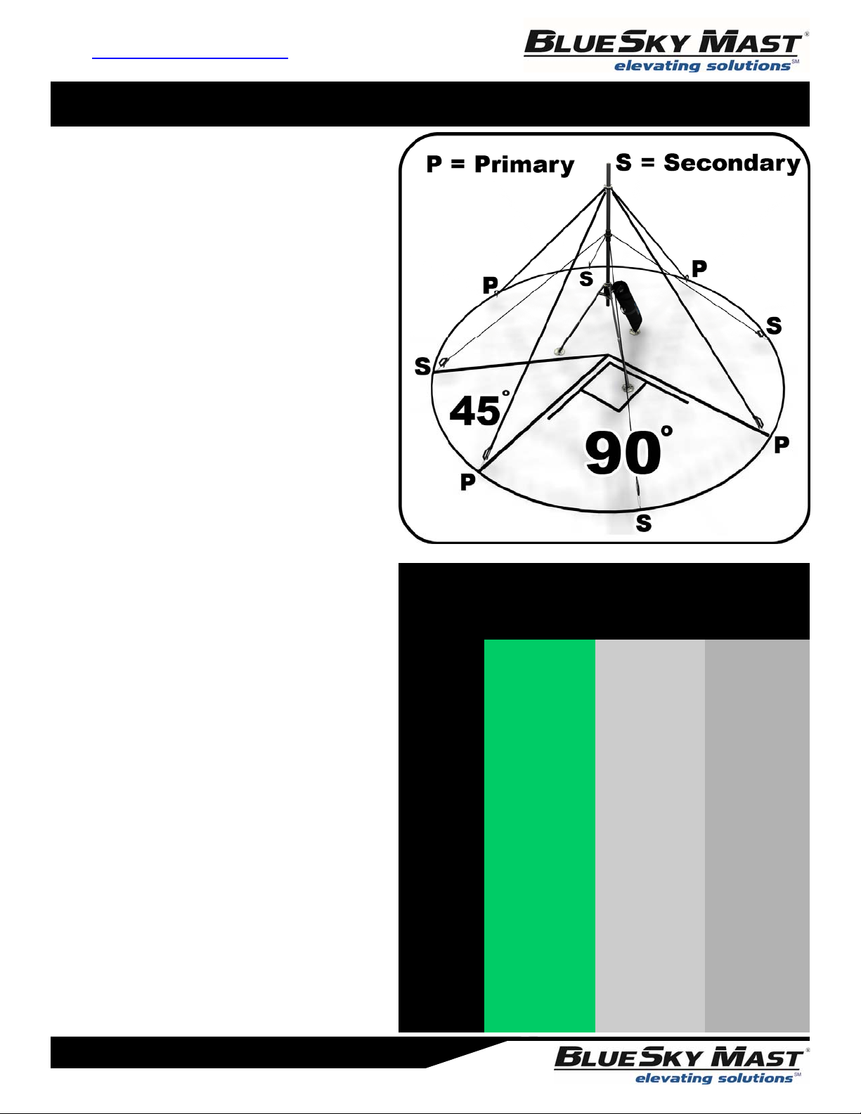
Primary and Secondary Guy Placement
BlueSky utilizes a 4 guy configuration to
help minimize the affect wind loading has on
the mast. The primary guys are always
deployed from the top of the mast and ex-
tend out at a 90 degree angle from each
other.
The secondary guys are deployed halfway
down the mast between the top of the
tripod and the primary guys. They are also
deployed at 90 degrees of each other and
45 degrees of the primary guy ropes.
The primary and secondary guys are always
deployed at the same distance or anchor
radius from the base of the mast.

AL1 Standard Series Mast - Load Tables
www.BlueSkyMast.com
877-411-6278
Page 12
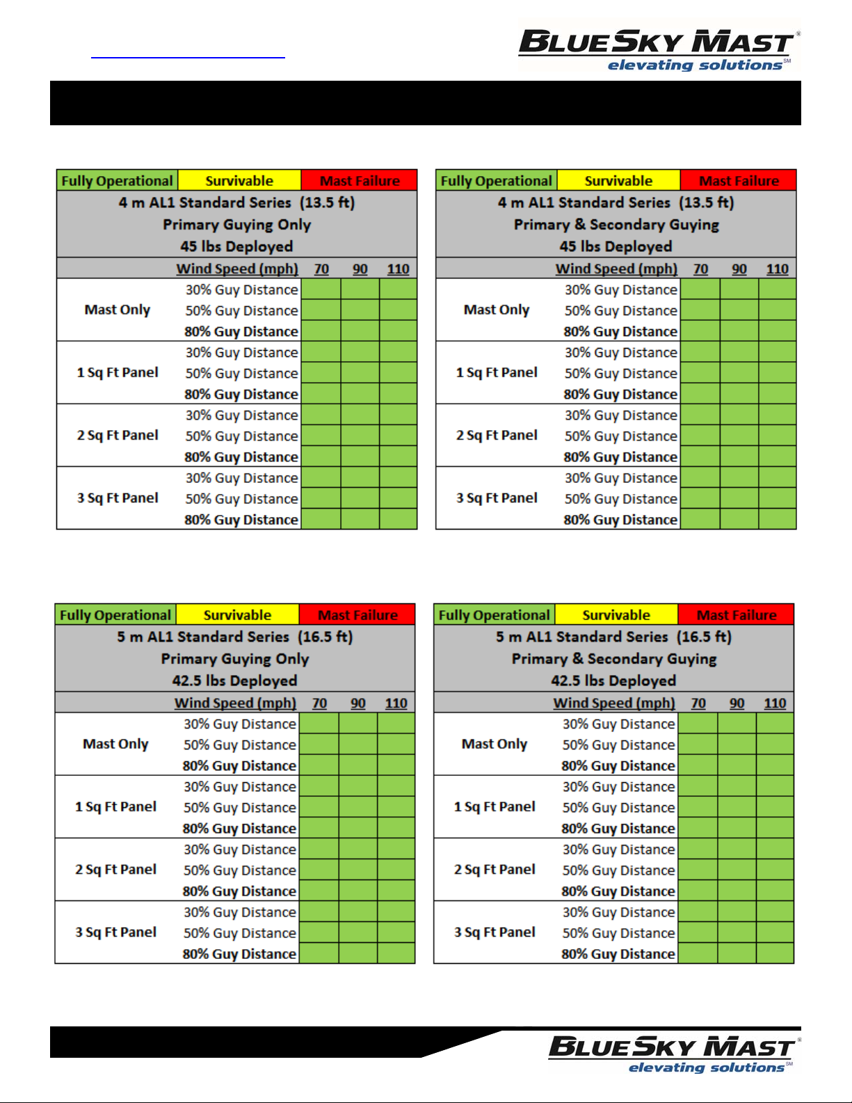
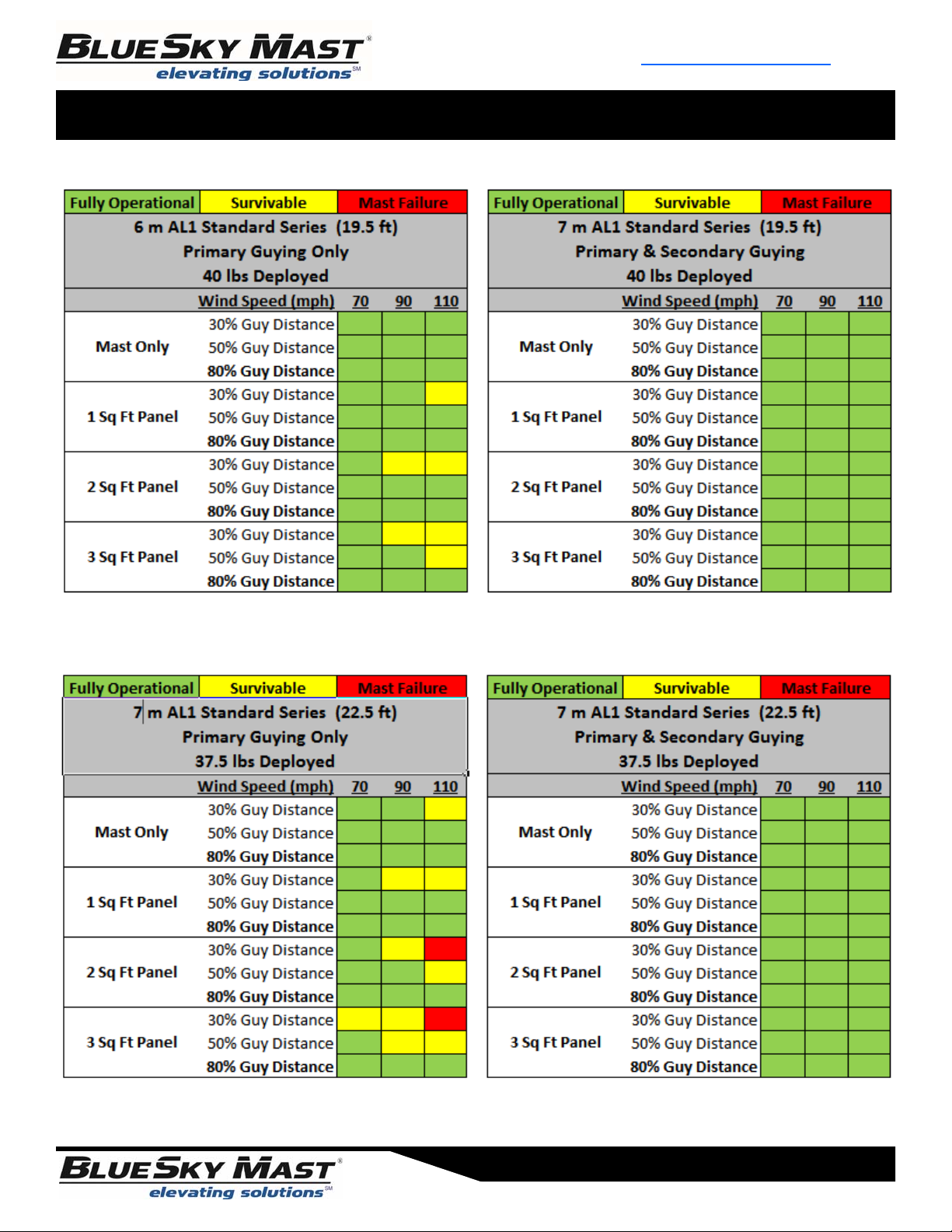
All calculations are based on the assumption that the tripod has been secured to the ground and is immovable and
that the guy stakes holding the guy ropes have been secured to the ground and are immovable. Different types of
soil conditions can negatively impact wind and load calculations and should be considered before deploying the mast.
AL1 Standard Series Mast - Load Tables
Page 13
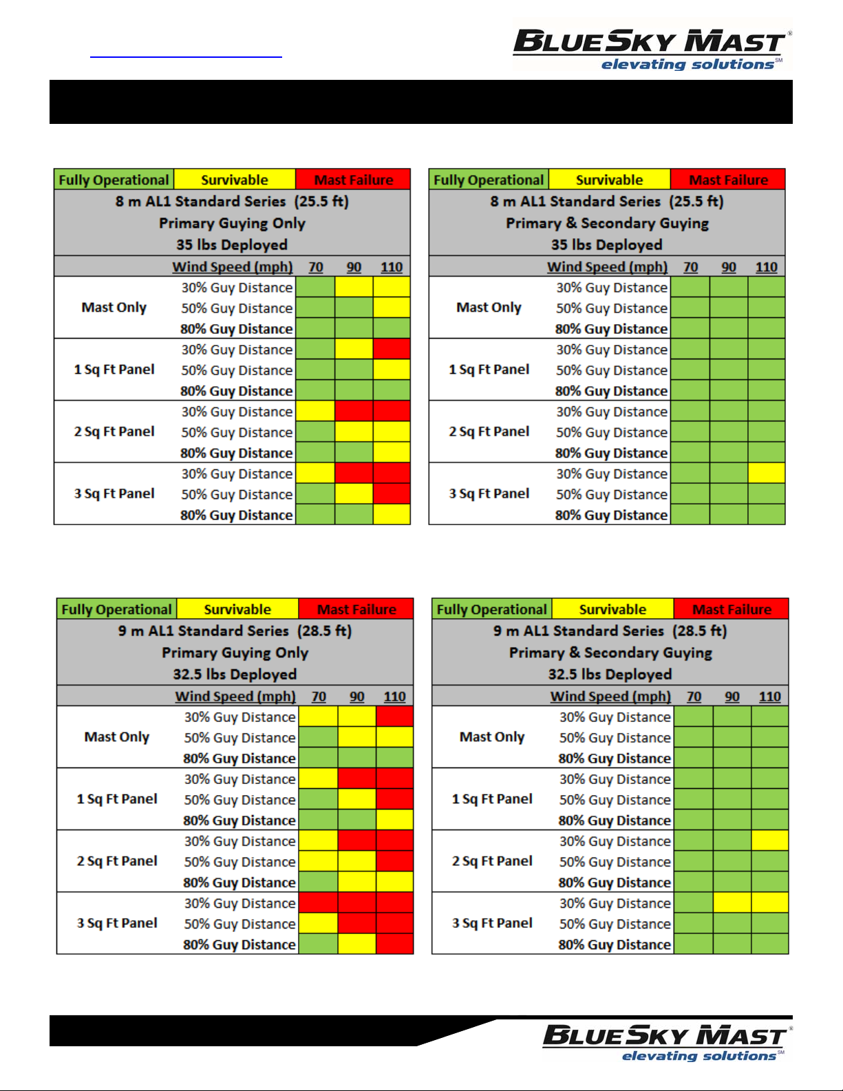
All calculations are based on the assumption that the tripod has been secured to the ground and is immovable and
that the guy stakes holding the guy ropes have been secured to the ground and are immovable. Different types of
soil conditions can negatively impact wind and load calculations and should be considered before deploying the mast.
AL1 Standard Series Mast - Load Tables
www.BlueSkyMast.com
877-411-6278
Page 14
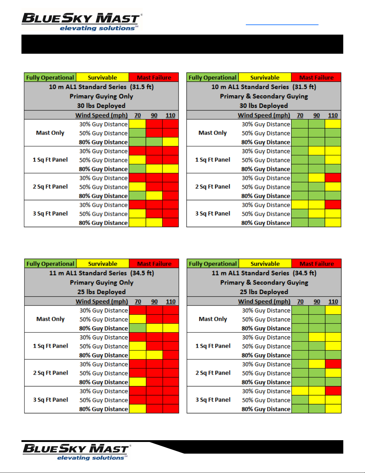
All calculations are based on the assumption that the tripod has been secured to the ground and is immovable and
that the guy stakes holding the guy ropes have been secured to the ground and are immovable. Different types of
soil conditions can negatively impact wind and load calculations and should be considered before deploying the mast.
AL1 Standard Series Mast - Load Tables
Page 15
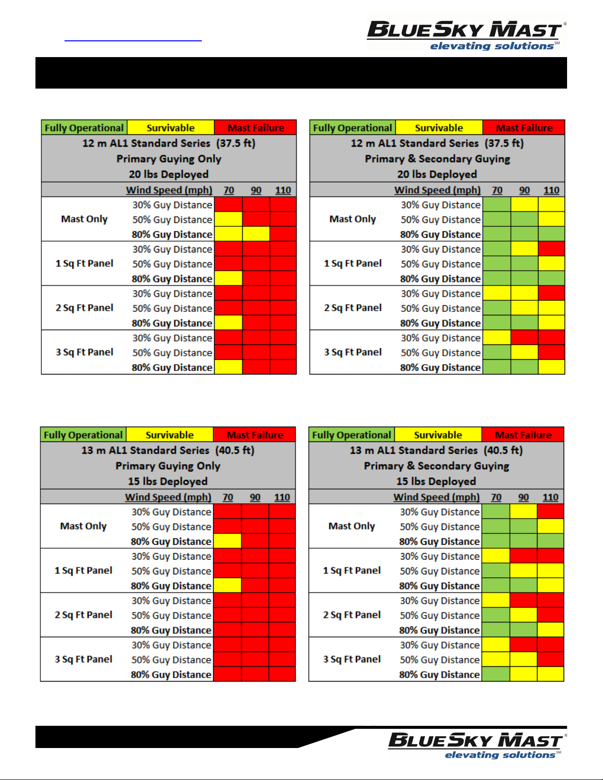
All calculations are based on the assumption that the tripod has been secured to the ground and is immovable and
that the guy stakes holding the guy ropes have been secured to the ground and are immovable. Different types of
soil conditions can negatively impact wind and load calculations and should be considered before deploying the mast.
AL1 Standard Series Mast - Load Tables
www.BlueSkyMast.com
877-411-6278
Page 16
All calculations are based on the assumption that the tripod has been secured to the ground and is immovable and
that the guy stakes holding the guy ropes have been secured to the ground and are immovable. Different types of
soil conditions can negatively impact wind and load calculations and should be considered before deploying the mast.
AL1 Standard Series Mast - Load Tables
Page 17
All calculations are based on the assumption that the tripod has been secured to the ground and is immovable and
that the guy stakes holding the guy ropes have been secured to the ground and are immovable. Different types of
soil conditions can negatively impact wind and load calculations and should be considered before deploying the mast.

AL1 Standard Series Mast - Load Tables
www.BlueSkyMast.com
877-411-6278
Page 18
All calculations are based on the assumption that the tripod has been secured to the ground and is immovable and
that the guy stakes holding the guy ropes have been secured to the ground and are immovable. Different types of
soil conditions can negatively impact wind and load calculations and should be considered before deploying the mast.

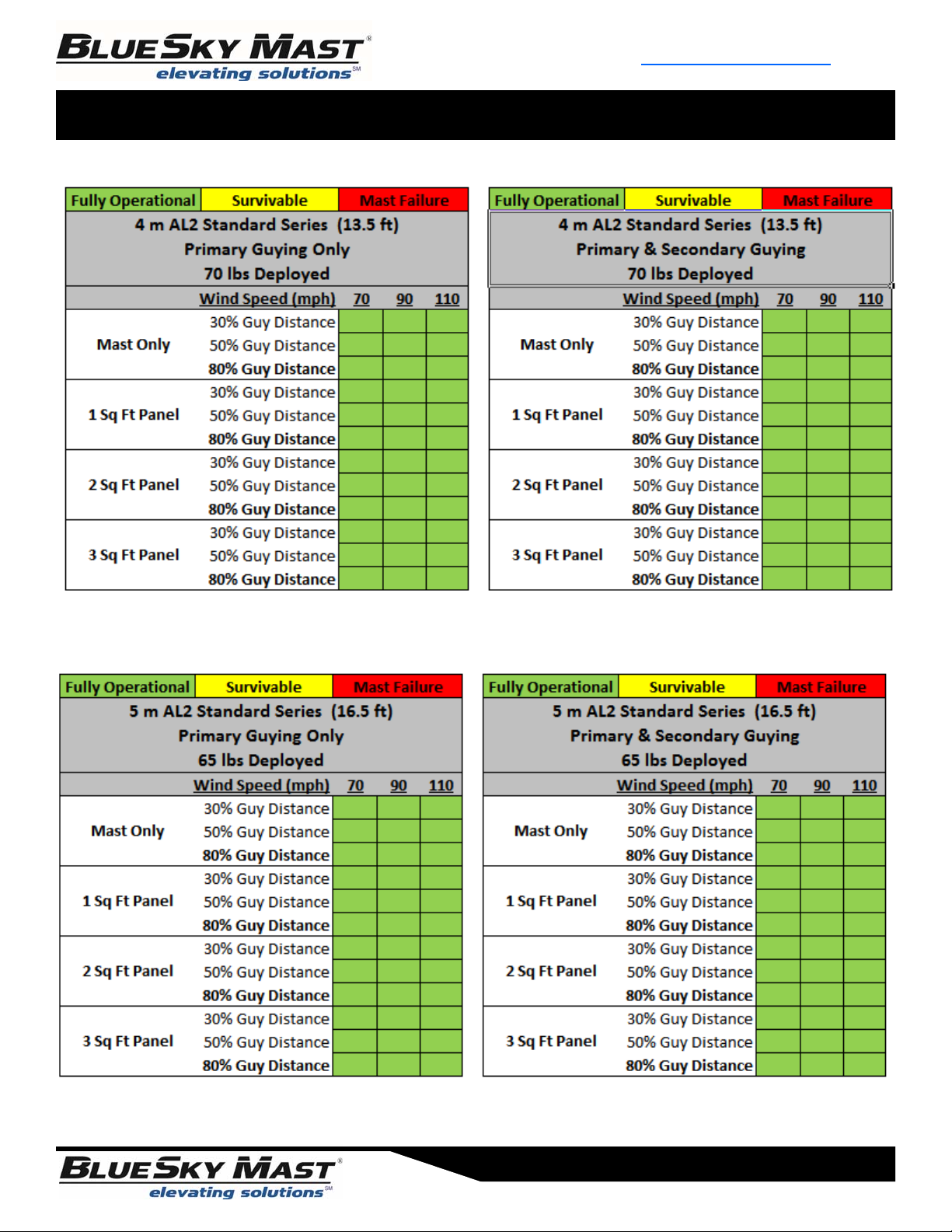
AL2 Standard Series Mast - Load Tables
Page 19
All calculations are based on the assumption that the tripod has been secured to the ground and is immovable and
that the guy stakes holding the guy ropes have been secured to the ground and are immovable. Different types of
soil conditions can negatively impact wind and load calculations and should be considered before deploying the mast.
AL2 Standard Series Mast - Load Tables
www.BlueSkyMast.com
877-411-6278
Page 20
All calculations are based on the assumption that the tripod has been secured to the ground and is immovable and
that the guy stakes holding the guy ropes have been secured to the ground and are immovable. Different types of
soil conditions can negatively impact wind and load calculations and should be considered before deploying the mast.
This manual suits for next models
1
Table of contents
Other BlueSky Mast Antenna manuals


