BlueSun PV User manual

Version 202205
Installation Guide for Bluesun
Solar Shingled Double-Glass
PV Module

I
Contents
1 Scope ................................................................................ 1
2 The introduction of installation manual ......................................................1
2.1 Overview ............................................................................. 1
2.2 Applicable products ..................................................................... 1
3 Product information ..................................................................... 2
3.1 Profile structure and component description of the double glass modules ........................... 2
3.2 Module tag information .................................................................. 3
4 Installation ............................................................................ 4
4.1 General safety ......................................................................... 4
4.2 Electrical properties safety ................................................................5
4.3 Handling safety ........................................................................ 5
4.4 Installation safety ....................................................................... 6
5 Installation condition .................................................................... 7
5.1 Working environment ................................................................... 7
5.2 Installation position ..................................................................... 7
5.3 Tilt angle selection ......................................................................8
6 Mechanical installation .................................................................. 8
6.1 Conventional requirement ................................................................ 9
6.2 Three kinds of Mounting ................................................................. 9
6.3 Module installation .................................................................... 10
6.4 Wiring method ........................................................................ 19
7 Electrical Installations ....................................................................21
7.1 General With Regard to Electrical Installation ............................................... 21
7.2 Cables and wiring ..................................................................... 22
7.3 Connectors ........................................................................... 22
7.4 Bypass diodes ........................................................................ 23
7.5 Grounding ........................................................................... 23
8 Maintenance ..........................................................................24
8.1 Usual maintenance ..................................................................... 24
8.2 Visual inspection of modules ............................................................. 25
8.3 Check cables and connectors ............................................................. 25

1
1 Scope
This installation manual specifies the installation and maintenance requirements for crystalline silicon PV
double glass modules (hereinafter referred to as "modules") manufactured by Bluesun Solar Co.,Ltd.
(hereinafter referred to as "Bluesun").
This installation manual is intended for the installation and maintenance of modules, and helps customers
to correctly install the photovoltaic power generation system, so that the design system can realize its potential.
2 The introduction of installation manual
2.1 Overview
Thanks for choosing the crystalline silicon PV module of Bluesun Solar Co.,Ltd. This manual contains
important electrical and mechanical installation information. For correct installation and stable power output,
please install and maintain the modules Carefully read and understand all installation instructions in the
manual, and keep this manual in a safe place for future reference (care and maintenance) and in case of sale or
disposal of the modules.
This manual does not constitute a warranty, expressed or implied. Bluesun does not assume responsibility
and expressly disclaims liability for loss, damage, or expense arising out of or in any way connected with
installation, operation, use or maintenance of modules.
The PV modules should be installed in accordance with all safety precautions and local laws and
regulations of this manual and should be installed and serviced by qualified personnel with knowledge of the
mechanical and electrical requirements of the system.
The mechanical and electrical installation of the PV modules shall be made in accordance with applicable
laws and regulations, including electrical, construction and electrical connection requirements. These
regulations vary depending on the installation site, such as building roofs, surface mounts, in-vehicle
applications, and so on. The requirements may vary depending on the installation system voltage, the use of
DC or AC. Please refer to the relevant local laws and regulations.
Any questions, please contact with the salesman or customer service personnel of Bluesun solar for
further explanations.
2.2 Applicable products
This manual is intended for use with the following modules:
Double glass modules: 72 version of the series, 60 version of the series(Where 'xxx' denotes power)
Horizontal double glass modules:

2
BSMxxxCM5-72SD BSMxxxCM5-60SD
BSMxxxPM5-72SD BSMxxxPM5-60SD BSMxxxPMB5-72SD BSMxxxPMB5-60SD
BSMxxxPM5-72SDA BSMxxxPM5-60SDA BSMxxxPMB5-72SDA BSMxxxPMB5-60SDA
BSMxxxPM5-72SDA-F BSMxxxPM5-60SDA-F BSMxxxPMB5-72SDA-F BSMxxxPMB5-60SDA-F
Vertical double glass modules
BSMxxxPMB6-57SDC, BSMxxxPMB6-68SDC
BSMxxxPMB6-54SDC, BSMxxxPMB6-65SDC
BSMxxxPMB6-58SDC, BSMxxxPMB6-69SDC
3 Product information
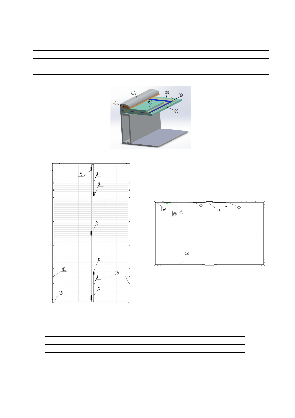
3.1 Profile structure and component description of the double glass modules
3.1.1 Double glass frameless modules
Figure 1 Double glass framelss modules cross section
Figure 2 Fixture installation
Figure 3 Installation of flexible
Figure 4 Back hook installation
3
back reinforcement
Table 1 Componets of double glass framelss modules
1、corner protector
2、Glass
3、EVA/POE
4、Solar Cell
5、Backsheet
6、Adhsive
7、Junction box
8、Cable
9、Connector
10、Lable
14、back reinforcement
15、Back hook
3.1.2 Double glass belt frame modules
Figure 5 Double glass belt frame modules cross section
Figure 6 Vertical double glass belt frame modules
Figure 7 Horizontal double glass belt frame modules
Table 2 Componets of double glass belt frame modules
1、Frame
2、Glass
3、EVA
4、Solar Cell
5、Backsheet
6、Adhsive
7、Junction box
8、Cable
9、Connector
10、Lable
11、Ground hole
12、Mounting hole
13、Drainage hole
3.2 Module tag information

4
Each PV module is affixed with two kinds of labels, providing the following information:
a) Label: Describes the product name, PV module model, nominal power, rated voltage, rated current,
open circuit voltage, short circuit current, maximum system voltage, PV module size and weight under
standard test conditions.
b) Series number: Each module has a unique bar code number, each bar code number has 18 letters and
numbers. The bar code is permanently encapsulated inside the module, as can be seen clearly from the top
right corner of the module. The bar code number allows you to trace information about the module production
process.
3.3 Module electrical performance parameters
The electrical performance parameters of the module were measured under standard test conditions
(irradiance of 1000 W / m², AM 1.5 spectra, ambient temperature of 25 ° C) with a test uncertainty of ± 3%.
The maximum system module voltage is 1500V. Refer to technical specifications for electrical performance
parameters.
4 Installation
4.1 General safety
4.1.1 Bluesun solar’s modules have been evaluated by according to IEC61215 and IEC61730, Protection Class
Ⅱ, modules rated for use in this protection class may be used in system operating at greater than 50V DC or
240W. The class of fire rating is Class C(According to the standard is UL790).
4.1.2 The maximum rating of a fuse connected in series with an array string is typically 20A, but the actual
module specific rating can be found on the product label and in the product datasheet.
4.1.3 The installer should abide by the relevant local laws and regulations when installing module. It is need to
obtain the required certificates in advance when necessary, such as the building permit.
4.1.4 Installing solar systems require specialized skills and knowledge. Installation should be performed only
by qualified person. Installers should assume the risk of all injuries that might occur during installation, such
as electric shock.
4.1.5 PV modules are designed for outdoor use, modules may be mounted on ground, rooftops, vehicles or
boats. Proper design of support structures is the responsibility of the system designers or installers. When
modules are mounted on rooftops, fire-protection rating of the final structure should be considered, and also
the later maintenance. The rooftops and support structure for PV system should only be certified by
architectural experts or engineer, which have a formal complete structure analysis results.
4.1.6 For your safety, do not install the modules without safety precautions.
4.1.7 For your safety, do not install or handle the modules under wet or adverse environment, including but not
limited to strong wind, gusty wind, frosted roof surfaces, wet environment.

5
4.1.8 Meaning of crossed –out wheeled dustbin:
Do not dispose of electrical appliances as unsorted municipal waste, use
separate collection facilities.
Contact your local government for information regarding the collection
systems available.
If electrical appliances are disposed of in landfills or dumps, hazardous
substances can leak into the groundwater and get into the food chain,
damaging your health and well-being.
When replacing old appliances with new ones, the retailer is legally obligated
to take back your old appliance for disposals at least free of charge.
4.2 Electrical properties safety
4.2.1 When a module is exposed to sunlight or other light sources, a direct current is present inside the module,
and electrical contact with the module may result in an electrical shock hazard.
4.2.2 In order to avoid arc and electric shock, please do not disconnect electrical connections under load. Keep
all electrical connectors dry and clean, and ensure that they are in proper working condition. Do not insert
other metal objects into the connector, or in any other way.
4.2.3 Do not apply paint or adhesive to module surface. Do not wipe modules with corrosive chemicals.
4.2.4 Do not use mirrors or other magnifiers to focus sunlight on the modules. Do not expose the backside of
modules directly to sunlight for a long time.
4.2.5 Do not change the configuration of the bypass diodes. Do not disassemble the modules.
4.2.6 Do not contact with module surface when the module is wet unless to clean the modules, please
following requirements mentioned in this manual when cleaning.
4.3 Handling safety
4.3.1 Do not open the box until it reaches the installation location. Keep the package in a dry and dry place.
4.3.2 PV modules Unpacking Please refer to Unpacking manual of standard package of Bluesun solar
photovoltaic modules. During all handling procedures, make sure that the modules are not subject to large
vibrations, that the modules fall to the floor or that objects fall on the module, as this will Damage to the
modules or solar cell. Special care must be taken not to bump, scrape, or press against the back of the module.
Keep children and unauthorized person away from the modules while transporting or installing them. Improper
transportation or placing may lead to glass breakage or power loss of the modules, resulting in the loss of the
use value of modules.
4.3.3 Handle modules with care, lift and put down modules gently. It is forbidden to carry or lift the modules
by grabbing the junction box or cables. Two or more people must hold the module with both hands.

6
4.3.4 Do not step on, stand or sit on the module, which can damage the module and create a risk to people.
4.3.5 Do not place any heavy objects on the front or back of the module, and do not place the module on a
sharp object surface.
4.4 Installation safety
4.4.1 Abide by the safety regulations for all other modules used in the PV system, including wiring and cables,
connectors, controllers, inverters, storage batteries, etc., and use suitable equipment, connectors, wiring and
mounting system for a PV system. If the PV system is used in storage batteries, the configuration with the
modules should follow the advice of the storage batteries manufacturer. The same size, the same specifications
of the model can be connected in series.
4.4.2 Do not install or handle the modules when they are wet or during strong wind. Keep the junction box’s
cover closed.
4.4.3 Modules of the glass with the role of protection modules, unreasonable operation will cause glass broken.
Damaged modules have the risk of electric shock and fire, such modules can not be repaired or repaired,
should be replaced immediately.
4.4.4 When exposed to direct sunlight, one individual solar module may generate DC voltages greater than 30
volts. It is extremely dangerous to contact it.
4.4.5 To reduce the risk of electric shock or burning, you can install modules with opaque material on the
surface of the module. The mounting of the array of modules must be carried out with an isolating solar
installation. Do not wear metal rings, watches, earrings and other metal accessories when installing or
servicing PV systems. Do not touch the electrical parts of the module directly by hand. Use an insulating tool
to make electrical connections and keep the tool dry.
4.4.6 In order to reduce or avoid the mismatch effect of the array, it is suggested to connect the components
with similar electrical performance on the same string.
4.4.7 The maximum system voltage indicated in the rating label is 1500V. During the system Installation, the
maximum open circuit voltage in series cannot exceed the maximum system voltage.
4.4.8 During modules interconnection, ensure to fix the connecting cables to supporting bracket, so as to
restrict the swing amplitude of the slack part of the cables.
4.4.9 Abide by the allowable minimum bending radius of the cables (suggest no less than 43mm).
4.4.10 Always protect the cable with conduit where animals or children can touch it.
4.4.11 Please use the connector which is specially designed for photovoltaic system, and assemble it with the
tools recommended or specified by the manufacturer. In case that the connector applicable to the solar
photovoltaic system is required, please contact the local supplier. Ban different connectors to plug each other.
4.4.12 Make sure that the polarity is correct when connecting the module with inverter, storage battery or
combiner box to avoid the damage of bypass diodes in the modules due to incorrect polarity.

7
4.4.13 Ensure that other components in the system do not cause destructive mechanical or electrical
performance impacts on components.
4.4.14 Modules can't be used to replace the roof and wall materials, partial replacement is not allowed.
4.4.15 Any part (including nameplate) of modules supplied by Bluesun Solar Co.,Ltd can't be dismantled
without permission.
5 Installation condition
5.1 Working environment
Bluesun solar’s PV module should operate in the following environmental conditions:
5.1.1 Ambient temperature: -20℃ to +45℃
5.1.2 Operating temperature of the module: -40℃ to +85℃
5.1.3 Humidity: ≤85%RH
5.1.4 Mechanical load pressure the modules have passed the mechanical load test of wind pressure of 1200Pa
and snow pressure of 5400Pa; at the same time, they have passed the mechanical load test of wind pressure of
2400Pa and snow pressure of 3600Pa. (Only limited to the PV module models mentioned in this manual).
Note: The module mechanical load is based on the installation method and installation site, in the calculation
of mechanical load by the professional installer according to the system design requirements to calculate.
5.2 Installation position
5.2.1 In most applications, PV modules should be installed in a location where they will receive
maximum sunlight throughout the year. In the northern hemisphere, modules should typically face south, and
in the southern hemisphere, modules should typically face north.
5.2.2 The module shall be installed in the place where the sunshine is adequate. the module surface shall not be
partly shaded by trees, building, clothes, tools, packaging materials, etc. because these objects will form
shadow in the module surface leading to loss of system output power.
5.2.3 The module shall be installed in the well-ventilated place; meanwhile, enough space for airiness shall be
sated at the back and sides of the module, so that the heat generated during operation can be radiated in time.
5.2.4 Modules can not be used in other excessive and harsh environments, such as hail, snow, sand, smoke, air
pollution, soot, flammable gases, near open flames, and highly corrosive substances (such as acid rain) , As
this will affect the module's safety and performance. If the installation environment is special, such as farm,
high humidity or wind and other large environment, please consult your local dealer for professional support
and confirmation. If you need to be installed at a high altitude, the altitude should not exceed 2000m.
5.2.5 Bluesun PV modules have passed IEC61701 salt-mist,but galvanic corrosion can occur between the
aluminum frame of the modules and mounting or grounding hardware if such hardware is comprised of
8
dissimilar metals. Bluesun modules can be installed at seaside locations 50m to 500m from the sea, but the
components should be protected against corrosion. For locations ≥500m from the sea, it is low risk with
salt-mist corrosion, only annual preventive maintenance is required.
5.2.6 Modules should be installed in suitable buildings, or other suitable place to install modules (such as the
ground, garage, building facades, roof).
5.2.7 If modules are installed in locations with frequent lightning activity, the modules must be protected
against lightning strikes.
5.2.8 Do not install the modules in this location with water immersion or near the sprinkler.
5.2.9 The pressure of the wind or snow after installation of the modules must not exceed the maximum
allowable load.
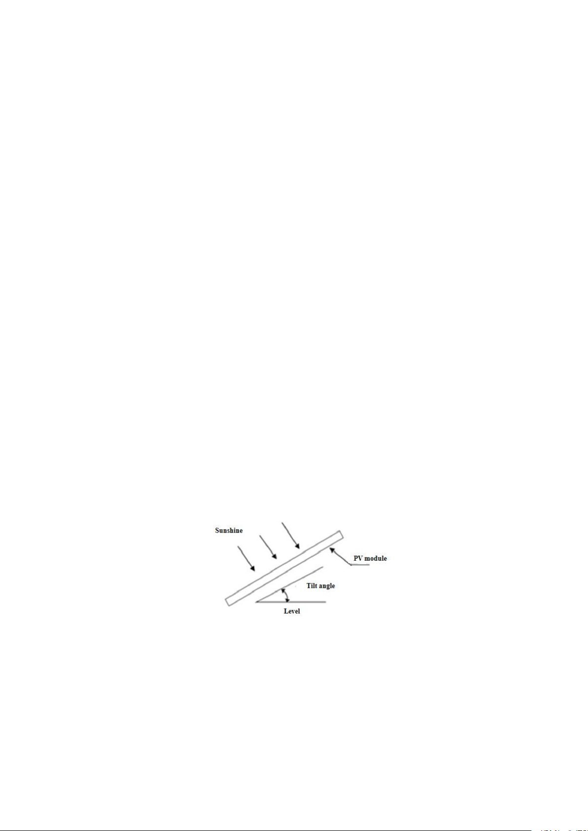
5.3 Tilt angle selection
5.3.1 The tilt angle of the Modules is measured between the surface of the modules and a horizontal ground
surface, the modules generates maximum power output when it faces the sun directly, as shown in figure 8.
5.3.2 Modules each element in series with the same array must be oriented in the same direction and angle.
Different installation directions and angles will cause the modules to absorb the total solar radiation difference,
causing the loss of output power, thus reducing the operating efficiency of the system.
5.3.3 The maximum power is generated when the sun is directed to the module, select the best installation
angle should be considered when the winter module power output. But external or otherwise artificially
concentrated sunlight shall not be directed onto the front or back face of the PV module.
5.3.4 In order to facilitate the cleaning modules and modules in the rain when the surface dust is easily washed
away by rain. For detailed installation angles, follow the advice given by the experienced PV module installer.
Figure 8 Module tilt angle
6 Mechanical installation
All of the installation methods described here are for reference only. Bluesun Solar Co.,Ltd is not responsible
for providing the relevant installation parts and module installation services.

9
6.1 Conventional requirement
6.1.1 Ensure that the installed modules and supporting rail of modules are strong enough, the entire PV system
consisting of modules must be able to withstand anticipated mechanical pressure. The installer must provide
the guarantee. The installation supporting rail must be tested by the third-party organization with the analysis
ability of Static Mechanical according to the local national or international standards.
6.1.2 The supporting rail must be made of environmental corrosion, anti-rust and UV-resistant materials.
6.1.3 Modules must be securely fastened to the supporting rail.
6.1.4 Drilling holes on the surface of module glass may void the warranty.
6.1.5 Forces generated during thermal expansion and contraction of the supporting rail may influence the
performance and use of the module, so make ensure that the minimum distance between two neighboring
frames is 10mm, but in order to ensure good ventilation. Suggest this distance between two neighboring frames
is 30mm.
6.1.6 In areas with large snow cover in winter, select a higher mounting bracket so that the lowest point of the
module will not be covered by snow for long periods of time. In addition, the lowest point of the module is
high enough to prevent the module from being obstructed by vegetation or trees.
6.1.7 The bearing surface of the supporting system must be smooth without any twist or deformation, and all
of them shall be at the same height without dislocation.
6.2 Three kinds of Mounting
6.2.1 Roof mounting
6.2.1.1 It is necessary to provide a special supporting rail for the roof mounting. When installing a module on a
roof or building, ensure that it is securely fastened and cannot fall or be damaged as a result of strong winds or
heavy snow. During roof mounting, check the building codes being used to ensure that the building and its
structure where the module is installed have adequate bearing and sealing capacity. The roof when penetrated
during module installation shall be properly sealed to avoid rainwater leakage.
6.2.1.2 To be suitable for operation, reduce steam condensation and facilitate the ventilation & heat dissipation
of the module during tile installation, the module shall be parallel to the wall or roof surface of the building,
and the distance between module and surface of the wall or roof shall be at least 50mm to prevent wiring
damage and to allow air circulation, ventilation and heat dissipation behind the module. For stacking type
installation, the module shall be installed on the fire-resistant roof. The Fire Resistance Rated Class of the
modules is Class C, and the modules are suitable for mounting on an above Class A roof. Do not install
modules on a roof or building during strong wind.
6.2.1.3 For the roof system installed in the area with relatively heavy snowfall or snow cover in the
meteorological records, the installer shall reinforce the supporting system at the lower frame of the module, in
order to prevent the lower frame from being pressed and damaged by the falling snow or freezing of the melt

10
ed snow. Bluesun solar suggests selecting the support reinforcing mechanism shown in figure 9.
T h e clam p
T h e u p p e r m o d u le
T h e s u p p o rt rail
T h e u n d er m o d u le
T h e s tren g th s u p p o rt
Figure 9 Schematic diagram of reinforcement mounting of module
6.2.2 Pole mounting
When installing a module on a pole, choose a pole and supporting rail that will withstand the anticipated
wind power of the local area. The pole must be constructed on a solid foundation.
6.2.3 Ground mounting
Select the height of the mounting system to prevent the lowest edge of the module from being covered by
snow for a long time in winter in areas with heavy snowfalls. The module shall be installed on the supporting
rail with appropriate height instead of being directly laid on the ground. In addition, the lowest portion of the
module shall be high enough (≥900 mm) from ground, so that it is not shaded by plants and trees, or damaged
by sand and stone driven by wind, or not shaded by the mud splashed by rain water.
6.3 Module installation
6.3.1 General rules
6.3.1.1 The connection between the module and the system bracket can be installed by fixture or bracket hooks,
or by flexible special hooks between the module and the tightwires. If customers have special clamping and
installation schemes that are not included in this manual, please consult local distributors for professional
support. module installation must be carried out in accordance with the following methods, otherwise the
quality assurance will fail.
6.3.1.2 Bluesun modules have reached the IEC standard on the mechanical load requirements. Bluesun module
can withstand the wind pressure of 2400Pa and the snow pressure of 5400Pa (Only the module models covered
in this manual are available ), it is recommended that the system designer or installer perform the load
calculations.
6.3.1.3 The supporting rail and other materials required (such as screw) shall be made of durable, resistance to
11
environmental corrosion, anti-rust and UV-resistant materials.
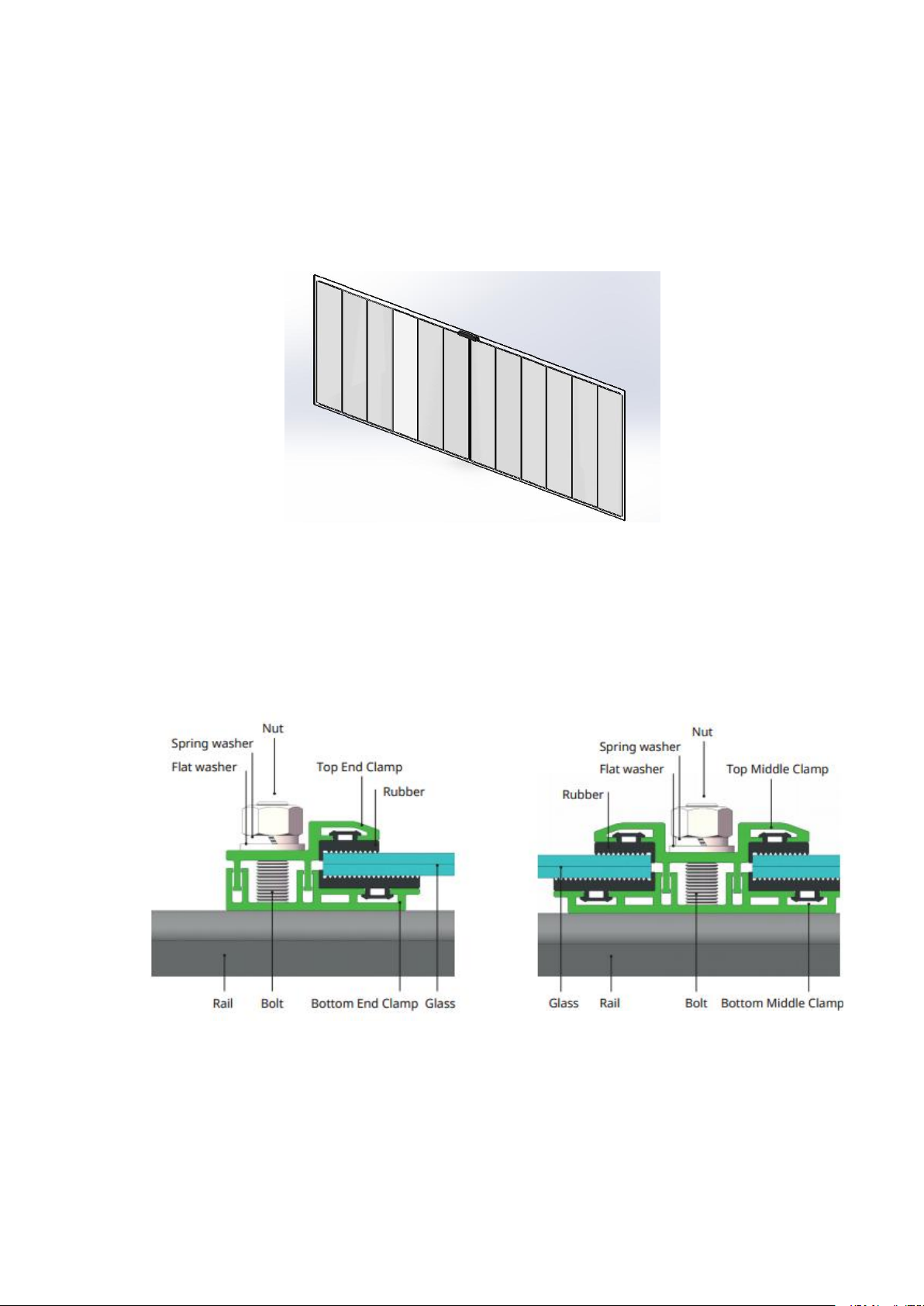
6.3.2 Fixture installation(frameless modules)
6.3.2.1 Fixture installation is suitable for modules without hook as shown in Figure 10. Fixture recommended
aluminum alloy material or with the performance of metal material. A suitable cushion is required between the
fixture and the module glass. EPDM rubber is recommended.
Figure 10 Double glass module suitable for fixture installation
6.3.2.2 Each module is recommended to be fixed with 4 or 6 clamps, 2 or 3 clamps on each side of the module.
According to local Environment (depending on wind power and snow loads), additional clamps may be
required to ensure modules and PV system to withstand anticipated mechanical pressure. We recommends
using the following clamps(as shown in Figure 11, Figure 12),or approved by reputable solar installer or
systems integrator.
Figure 11 Fasten the Fringe modules
Figure 12 Fasten the Middle modules
6.3.2.3 The fixed clamp is clamped on the long side of the module, use the spring washers, flat washers and
bolts to fix the modules to the mounting bracket. Note that both ends should be in the center symmetrical
position. It is recommended to use the M8/ bolts and the matching screws to fix the screws. Tightening torque
of the size of 17 ~ 23N • m.

12
6.3.2.4 Do not bend the modules while installing the modules. The mounting parts can not block the cells, do
not scratch the glass surface of the module. It is recommended that the overlapping part of the module and the
clamp should be 11-15mm in width, the length of the fixture should be at least 200mm, and the minimum
thickness of the fixture should be at least 3mm.
6.3.2.5 The position of the clamp is critical to the reliability of the installation. The recommended clamping
range is shown in Table 3:
Table 3 The clamping range of the fixture
Module type
Design Mechanical
Loading/Pa
Safety factor= 1.5
(Positive/ Negative)
A/mm
B/mm
C/mm
E/mm
F/mm
BSMxxxCM5-72SD
BSMxxxPM5-72SD
BSMxxxPMB5-72SD
3600/1600
1959
1983
1076
1096
392±50
400±50
11~15
11~15
≥200
≥200
BSMxxxPM5-72SDA
BSMxxxPMB5-72SDA
3600/1600
BSMxxxCM5-60SD
BSMxxxPM5-60SD
BSMxxxPMB5-60SD
3600/1600
1639
1076
329±50
11~15
≥200
BSMxxxPM5-60SDA
BSMxxxPMB5-60SDA
3600/1600
Note:
A: Length of this type of module.
B: Width of this type of module.
C: The distance of clamp center1 from the edge of
this type of module.
E: Clamped width of the module by the clamp of
this type of module.
F: length of the clamp.
*Tips: Bluesun does not guarantee the consequences caused by incorrect installation methods without following this
installation manual. When you take fixture installation, please pay attention to the following points:
(a) The fixture is mounted on the long side of the modules. (b) The fixture shall not produce shadow on the glass surface
of the modules. (c) The guide rail and the long side of the modules are installed vertically.
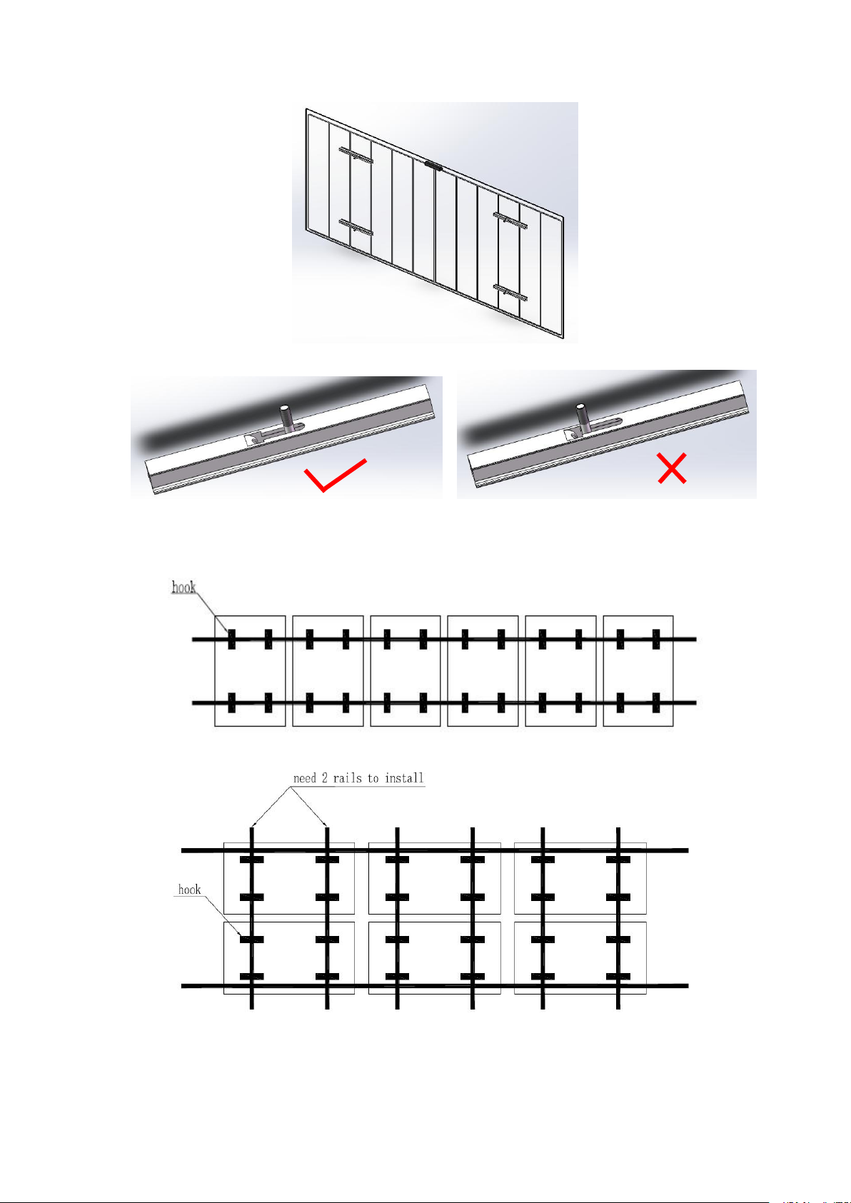
6.3.3 Hook installation (Suitable for single side double glass modules)
6.3.3.1 Modules can be attached through the hook on the back side of the module,by fixing the module to the
support rails with M8 bolt(for 60 version of the series ) and M10 bolt(for 72 version of the series ).The module
backside has 4 hooks. (Figure 13)The minimum distance between two modules is 10mm. The hex nut cannot
the fixed on the head of the insert place. The connecting surface of the support must keep smooth. (Figure 14)
13
Figure 13 Single side double glass modules installad with hook
Figure14 The hex nut cannot the fixed on the head of the insert place
6.3.3.2 The hook must be vertical with rails,the supporting rails need change when horizontal installation (add
2 rails).
Figure 15 Vertical installation
Figure 16 horizontal installation
6.3.4 installation of flexible system(Suitable for double glass modules)
6.3.4.1 the installation of flexible system is applicable to the components with flexible backbars as shown in

14
fig.9. Each component has 6 backbars on the back, and the minimum distance between the two components is
20mm. This component is applicable to the 1*7 (7-core) low-relaxation hot-dip galvanized or low-relaxation
Galfan steel cables with a diameter of 12.7mm.This assembly is not intended for epoxy or PE protected cables
or other construction (such as 1*19) cables.Cables shall meet the specification GB/T 5224-1995.This
installation manual has no specific requirements for the bearing capacity of steel cables;However, the axial
tensile elastic modulus (E) of the steel cable shall not be less than 170GPa.
Figure17 Suitable for the imbricated double glazing assembly with flexible backing
6.3.4.2 installation steps:
A) carry the components to the installation position (do not slide along the cable), and install a clamp under the
groove on the back to the parallel cable;
B) mounting and pressing:
Wire rope
Flexible back muscle

15
C) install locking bolt (tightening torque: 50 5N•m (about 5kg force))
Figure 18 Installation diagram of single block components
6.3.6 Fixture installation
6.3.6.1 Use a certain number of clamps to fix the modules on the mounting bracket. Bluesun recommends that
the clamps be clamped on the long frame of the module. The area of the A side of the module frame held by
each fixed clamp is not less than 400mm2 (clamp length: ≥50mm, The width of the contact between the fixture
and the A surface of the frame: 9~11mm).
6.3.6.2 When installing the fixing jig, do not touch the front glass, and do not scratch or deform the aluminum
frame during installation. At the same time, the jig cannot affect the normal operation of the module. Make
sure that the drain hole and ground hole are not blocked during installation.
press cake
bolt

16
6.3.6.3 Each module needs to be fixed with at least four fixtures, and each long frame is equipped with at least
two fixtures. According to the local application conditions (actual conditions of wind and snow), additional
fixtures may be required to ensure modules and systems are subjected to corresponding loads. Fixtures with
the following conditions are recommended (as shown in Figure 19) or approved by the module system
installer.
Fixture A: Fixture for edge module Fixture B: Fixture for intermediate modules
For the 30 frame, the recommended value of X is 29mm For the 30 frame, the recommended value of X is 20mm
For the 35 frame, the recommended value of X is 34mm For the 35 frame, the recommended value of X is 25mm
For the 40 frame, the recommended value of X is 39mm For the 40 frame, the recommended value of X is 30mm
Figure 19 Assembly fixture installation method
6.3.6.4 When clamping the fixture to the frame of the module, use spring washers, flat washers and bolts to fix
the module on the mounting frame. Note that both ends should be clamped in a symmetrical position in the
center. M8 bolts and matching The screw is fixed, and the torque of the screw is from 18N·m to24N.m .
6.3.6.5 If there is large snowfall or snow pressure in the module installation area and large wind pressure, it is
recommended that the customer adopt a 5400Pa reinforced installation solution to clamp the fixed module (as
shown in Table 4 recommendations) to increase the front of the module Resistant to static snow pressure and
dynamic wind pressure on the back, improving the system's pressure resistance.
Table 4 The clamping range of the fixture
The support rail
Clamp B
Clamp A

17
Note:
A: Length of this type of module.
B: Width of this type of module.
C: The distance of clamp center1 from the edge of this type of module.
D: The distance of clamp center 2 from the edge of this type of module.
E: Clamped width of the module frame by the clamp of this type of module.
F: Clamped length of the module frame by the clamp of this type of module.
G: The distance of clamp center 3 from the long edge of this type of module.
H: The distance of clamp center 4 from the edge of this type of module.
Bolt beam: width * height * length 40mm*40mm* 1500mm
* Note: Bluesun limited warranty will be void in cases where improper clamps or installation methods deviating from this manual are used.
When using clamps to fasten the modules, pay attention to the following requirements:
(a) Take care of the module frames, not to twist or deform them.
(b) Avoid the clamps’ shading influence the module.
(c) Not to damage the surface of module frame.
(d) Make sure that the module's drainage holes not be plugged.
Module Type
Installatio
n method
Design load*safety
factor(1.5)/Pa
A/mm
B/mm
C/mm
D/mm
E/mm
F/mm
G/mm
H/mm
BSMxxxPM5-72SDA-F
BSMxxxPMB5-72SDA-F
Long side
Installatio
n
5400/2400
1989
1101
398±5
0
/
9~11
≥50
/
BSMxxxPM5-72SDA-F
BSMxxxPMB5-72SDA-F
Long side
Installatio
n
5400/2400
1665
1101
333±5
0
/
9~11
≥50
/
BSMxxxPMB6-57SDC
Long side
Installatio
n
5400/2400
Or
3600/2400
2355
1090
570±5
0
/
9~11
≥50
/
425±
50
BSMxxxPMB6-68SDC
Long side
Installatio
n
5400/2400
Or
3600/2400
2355
1303
570±5
0
/
9~11
≥50
/
425±
50
BSMxxxPMB6-54SDC
Long side
Installatio
n
Positive5400
negtive2400
Or
Positive3600
negtive2400
2253
1096
545±
50
/
9~11
≥50
/
405±
50
BSMxxxPMB6-58SDC
Long side
Installatio
n
Positive5400
negtive2400
Or
Positive3600
negtive2400
2384
1096
575±
50
/
9~11
≥50
/
430±
50
BSMxxxPMB6-65SDC
Long side
Installatio
n
Positive5400
negtive2400
Or
2253
1303
545±
50
/
9~11
≥50
/
405±
50

18
Positive3600
negtive2400
BSMxxxPMB6-69SDC
Long side
Installatio
n
Positive5400
negtive2400
Or
Positive3600
negtive2400
2384
1303
575±
50
/
9~11
≥50
/
430±
50
6.3.6.5 For matters concerning clamp or installation not mentioned in this manual, contact the local dealer for
professional support
6.3.7 Screw installation
6.3.7.1 Use anti-corrosion M8 bolts to fix through the mounting holes on the module frame. Each module
needs to be fixed on 8 mounting holes (Screw installation only applies to THxxxPMB6-57SDC and
THxxxPMB6-68SDC PV modules ), as shown in Table 2 Schematic diagram of mounting holes for fixed
modules. If you need to strengthen the installation, it is recommended to use the 6.3.2 fixture installation
method.
6.3.7.2 When fixing with M8 bolts, spring washers and flat washers must be added to 4 symmetrical mounting
holes. See Table 1 for bolt fixing diagrams. The recommended torque for tightening screws is 16N·m . The
recommended accessories are shown in Table2:
Table 2 Bolt fixing assembly
Mounting holes location
Screw bolts fasten method
Recommend accessories
Module
M8 Screw
Flat washer
Spring washer
M8 Nut
The Support
rail
Part name
material
Dimension
Screw
Stainless
steel
M8× 16mm
Spring
washer
Stainless
steel
M8
Flat washer
Stainless
steel
100*25mm
Nut
Stainless
steel
M8
Bolt beam: width * height * length
40mm*40mm* > 2000mm
Module Type
Installation method
Design load*safety factor(1.5)/Pa
BSMxxxPMB6-68SDC
Long side Installation
positive5400/negtive2400
BSMxxxPMB6-57SDC
Long side Installation
positive5400/negtive2400
BSMxxxPMB6-54SDC
Long side Installation
positive5400/negtive2400
BSMxxxPMB6-58SDC
Long side Installation
positive5400/negtive2400
BSMxxxPMB6-65SDC
Long side Installation
positive5400/negtive2400
BSMxxxPMB6-69SDC
Long side Installation
positive5400/negtive2400
Table of contents
Popular Solar Panel manuals by other brands


PION POWER
PION POWER PVSolver GS-03 installation manual

BenQ
BenQ PM048M00 Series installation guide

HTP
HTP HP-30SC Installation, start-up, maintenance, parts, warranty

Sunman
Sunman eArc SMD Series installation manual

Sonnenstrom Fabrik
Sonnenstrom Fabrik Excellent installation guide

Suaoki
Suaoki SCB-120 user manual