lp-220 Rev. 000 Rel. 007 Date 2.12.18
5
C. Terminology
Solar terminology diers from region to region. To avoid confusion,
please note the following:
Supply – The plumbing line running from the outlet of the collector
to the tank.
Return – The plumbing line running from the tank (or heat
exchanger) to the inlet of the collector. This line incorporates the
circulation pump.
Insulation - Solar radiation level, expressed in kWh/m2/day or Btu/
ft2/day.
D. Possible System Designs
1. Open Loop Systems
An open loop system has potable water circulating through
the solar collectors. Open loop systems are recommended for
hot or warm climates that rarely freeze. For rare incidents when
ambient temperature drops below freezing, the controller can
be programmed to provide freeze protection by circulating warm
water from the tank through the solar collectors.
For open loop systems, the normal operating pressure should be
less than 72.5 psi. This operating pressure is provided via use of
a pressure limiting/reduction valve on the main supply line. An
expansion tank is required in open loop systems.
An open loop system may allow the solar collectors to stagnate to
prevent overheating of the storage tank. In the event of component
failure, the pressure relief valve must be able to release the
increased pressure, and should be rated to meet the maximum
possible pressure output of the solar collector(s). Please see Part 3
for sections regarding overheating.
2. Closed Loop Systems
A closed loop system uses non-potable heat transfer uid (HTF)
and must be pressurized to less than 72.5 psi. Closed loop systems
require an expansion tank to accommodate HTF expansion. The
system should be designed to minimize stagnation after tank
temperature has been met; extensive stagnation may increase pH
levels and glycol deterioration.
The expansion tank and plumbing must be properly sized so that
the safety pressure relief valve will not activate except in the event
of component failure or extreme conditions. The pressure release
must be set at no more than 113 psi. (There may be exceptions in
engineered designs for tall buildings.)
3. Drain Back Systems
The drain back method provides eective overheating and freeze
protection, making these systems well-suited for all climates.
When storage tank water temperature settings are reached or the
collector temperature falls below a set temperature, the pump shuts
o, allowing the HTF to drain back into the tank. Some drain back
systems use potable water as HTF. Others use a propylene glycol /
potable water mix.
Drain back systems require larger pumps to move HTF up and into
the solar collectors. Mounting the drain back tank as high as possible
within conditioned space will reduce pump size.
For drain back systems, the solar loop often operates at less than
25 psi, far lower than open or closed loop systems. These low
operating pressures do not require an expansion tank. A pressure
relief valve, installed on the drain back tank and piped in copper to
an appropriate drainage location, will provide sucient expansion
protection. This pressure relief valve and drain outlet pipe must
never be sealed or blocked. The pressure relief valve is intended to
be operated for safety purposes only.
NOTE: Supply and return connections to the collector must use
eccentric ttings or a tting arrangement that allows full draining
of header pipes. The collector or array should be mounted with a ¼”
pitch towards the supply port to facilitate the drain back process.
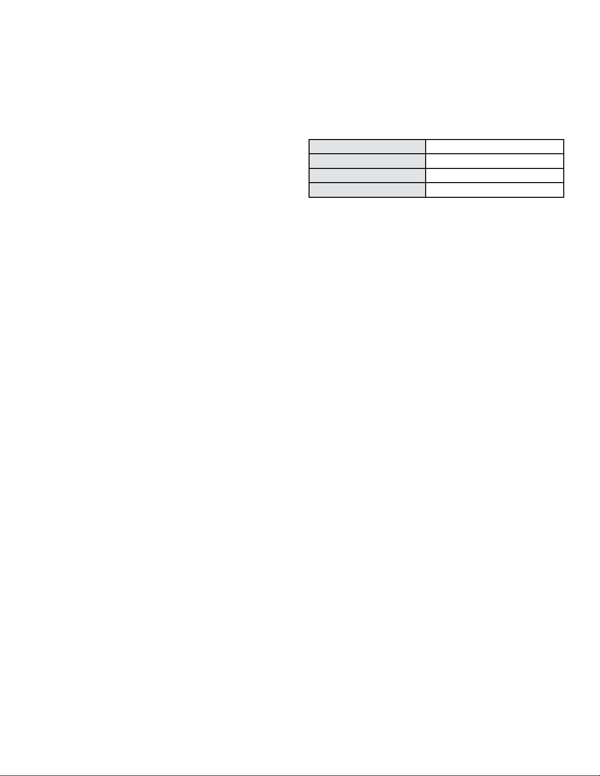
E. Fluid Quality
Water quality is very important. Water in direct ow through the
solar collectors must rst meet potable water requirements; any uid
circulated through the collectors should be non-corrosive to copper. In
addition, water quality must meet the following requirements.
Total Dissolved Solids < 500 ppm
Total Hardness < 7 grains (120 ppm)
Chlorides < 100 ppm
pH Levels 6.5 - 8.5
Table 1 - Water Quality Requirements
In areas with “hard” water (water hardness greater than 120 ppm)
where open loop format is used, lime scale may form inside the solar
collector. Scale deposits will reduce collector eciency and eventually
plug the collectors. In such regions, it is advisable to install a water
softening device to ensure the long term ecient operation of the
collector, or consider a closed loop system.
In order to meet health and safety regulations, glycol used should be
food grade propylene glycol, FDA rated as “generally recognized as
safe” (GRAS). If using a glycol / potable water mix, the water must meet
the above requirements. The glycol content of the liquid must not
exceed 50%, unless the manufacturer species that a dierent ratio
is recommended for use with solar water heaters. Glycol should be
checked periodically to prevent it from becoming acidic. Please refer
to guidelines provided by the glycol manufacturer regarding glycol
maintenance.
In addition, collector plumbing should slope toward the drain back
reservoir at ¼” per foot minimum to facilitate the drain back process.
If continual slope is not achievable, consider a pressurized closed loop
system.
F. Corrosion
Both copper and stainless steel are susceptible to corrosion when,
amongst other factors, high concentrations of chlorine are present.
The solar collector may be used for heating of spa or pool water, but
levels of free chlorine must not exceed 5 ppm. Otherwise, the copper
header could corrode.
NOTE: HTP DOES NOT WARRANT THE SOLAR COLLECTOR AGAINST
CORROSION-RELATED DAMAGE.
G. Freeze Protection
Freeze protection must be implemented in any regions that may
experience freezing conditions at any time throughout the year.
“Freeze tolerance limits are based upon an assumed set of
environmental conditions. Extended periods of cold weather, including
ambient air temperatures below the specied limit, may cause
freezing in exposed parts of the system. It is the owner’s responsibility
to keep the system’s freeze protection levels maintained in accordance
with the supplier’s instructions if the air temperature is expected to
approach the specied freeze tolerance limit.”
Open or closed loop systems: In areas with temperatures not falling
below 23oF, a dierential solar controller with freeze protection may
be used (e.g. requiring pump to circulate if the manifold temperature
approaches freezing). In an open loop system, a freeze valve (which
opens to allow water to dribble out) could also be considered.
Closed loop systems: In areas with temperatures falling below 23oF, a
propylene glycol / potable water mix should be used to provide freeze
protection. Please refer to glycol manufacturer’s specications about
the temperature ranges the liquid can withstand. Only food grade
propylene glycol, FDA rated as GRAS, should be used.
NOTE: HTP DOES NOT WARRANT THE SOLAR COLLECTOR AGAINST
FREEZE-RELATED DAMAGE.
H. Wind Stress
When installing the collector, please consider the issue of wind