PION POWER PVSolver GS-03 User manual
Pion Power PVSolver GS-03
GROUND RACKING SYSTEM INSTALLATION MANUAL
(UPDATED – July 12 2022)

Racking System Installation Manual, July 12, 2021
© 2021 Pion Power Inc. All Rights Reserved. Page 2
Contents
1 Racking Structure Brief ............................................................................................................................................. 3
1.1 Brand and Model .......................................................................................................................................... 3
1.2 Revision review ............................................................................................................................................. 3
1.3 Declaration ................................................................................................................................................... 3
2 Standards & References ............................................................................................................................................ 3
2.1 Standards ..................................................................................................................................................... 3
2.2 References .................................................................................................................................................... 3
3 Applicability & Certification ..................................................................................................................................... 4
3.1 Applicability ................................................................................................................................................. 4
3.1.1 Foundation ....................................................................................................................................... 4
3.1.2 Solar panel ....................................................................................................................................... 4
3.1.3 Inverter............................................................................................................................................. 4
3.2 Certifications ............................................................................................................................................... 4
4 Installation guide ......................................................................................................................................................5
4.1 Safety operation guide .................................................................................................................................5
4.2 Tools list .......................................................................................................................................................5
4.3 Installation (Sequence based on installation order) .......................................................................................5
4.3.1 Step-1: ........................................................................................................................................... 6
4.3.2 Step-2:............................................................................................................................................ 7
4.3.3 Step-3: ........................................................................................................................................... 8
4.3.4 Step-4:........................................................................................................................................... 8
4.3.5 Step-5: ........................................................................................................................................... 9
4.3.6 Step-6: ......................................................................................................................................... 10
4.3.7 Step-7: .......................................................................................................................................... 11
4.3.8 Step-8:.......................................................................................................................................... 11
4.3.9 Step-9: ......................................................................................................................................... 13
4.3.10 Step-10: ...................................................................................................................................... 13
4.3.11 Step-11: ...................................................................................................................................... 16
4.3.12 Final Inspection ............................................................................................................................ 24
5 Warranties ............................................................................................................................................................. 24
5.1 10 Years Limited Product Warranty- Shingle Roof Racking System ........................................................... 24
5.2 Warranty service contact ........................................................................................................................... 24
5.3 Warning ...................................................................................................................................................... 25

Racking System Installation Manual, July 12, 2021
© 2021 Pion Power Inc. All Rights Reserved. Page 3
1 Racking Structure Brief
1.1 BRAND AND MODEL
Brand: Pion Power PVSolver
Model: GS-03
1.2 REVISION REVIEW
Product version: V1-0213
Manual version: 01-0213
1.3 DECLARATION
a. The information contained in this document represents the current view of Pion Power PVSolver on the issues
discussed as of the date of publication. Since Pion Power PVSolver must respond to changing market conditions,
it should not be interpreted to be a commitment on Pion Power PVSolver part. Pion Power PVSolver cannot
guarantee the accuracy of any information presented after the date of publication. This document is for
informational purposes only and makes no guarantees, expressed, implied or statutory, to the information within
this document.
b. Complying with all applicable copyright laws is the responsibility of the user. Without limiting the rights under
copyright, no part of this document may be reproduced, stored in or introduced into a retrieval system, or
transmitted in any form or by any means (electronic, mechanical, photocopying, recording, or otherwise), or for
any purpose, without the expressed written permission of Pion Power PVSolver.
c. Pion Power PVSolver may have patents, patent applications, trademarks, copyrights, or other intellectual
property rights covering subject matter in this document. Except as expressly provided in any written license
agreement from Pion Power PVSolver, the furnishing of this document does not give you any license to these
patents, trademarks, copyrights, or other intellectual property.
d. All rights reserved. Pion Power PVSolver are either trademarks or registered trademarks of Pion Power PVSolver
or their affiliates in China/or other countries.
e. The names of actual companies & products mentioned herein may be the trademarks of their respective owners.
2 Standards & References
2.1 STANDARDS
CAN/CSA-086-01(R2006), Engineering Design in Wood, Standards Council of Canada;
CSA S304.1-04 (R2010), Design of Masonry Structures, Standards Council of Canada;
CAN/CSA-A23.3-04 (R2010), Design of Concrete Structures, Standards Council of Canada;
CAN/CSA -A23.1-14/A23.2,14 (R2014), Concrete materials and methods of concrete construction / Test
methods and standard practices for concrete, Standards Council of Canada;
CAN/CSA-S16-01 (R2007), Limit States Design of Steel Structures, Standards Council of Canada;
CAN/CSA-S413-14(R2012), Parking structures, Standards Council of Canada;
2.2 REFERENCES
Ontario Building Code 2012 4.1.6 Snow Load;
Ontario Building Code 2012 4.1.7 Wind load;
Ontario Building Code 2012 9.4.3 Deflections

Racking System Installation Manual, July 12, 2021
© 2021 Pion Power Inc. All Rights Reserved. Page 4
3 Applicability & Certification
3.1 APPLICABILITY
3.1.1 FOUNDATION
Helical pile
Ballasted concrete block
3.1.2 SOLAR PANEL
60-cells, 72-cells, and other customized solar panels
Panel frame height: 30mm, 35mm,40mm,45mm
3.1.3 INVERTER
Micro inverter
Power Optimizer
String inverter
3.2 CERTIFICATIONS
Certification: UL2703
Testing involved:
Bonding Path Resistance Test
Temperature Cycling test
Humidity Test
Mechanical Loading Test
Bonding Conductor Test

Racking System Installation Manual, July 12, 2021
© 2021 Pion Power Inc. All Rights Reserved. Page 5
4 Installation guide
4.1 SAFETY OPERATION GUIDE
1. The manual must be read and understood before installation. Workers must comply with all of these safety
instructions to minimize the risk of danger, property damage and personal injury.
2. All installations must be performed by qualified personnel in compliance with all applicable codes including O.B.C
2012 and N.B.C 2010.
3. Always check with local building and safety departments for specific codes and permits.
4. Make sure that the building structure can support the racking system under all the applicable design loads
including but not limited to snow, rain, wind and seismic loads per these codes.
5. All applicable OSHA (Occupational Safety and Health Act) guidelines must be followed to ensure proper safety.
6. Always use the appropriate tools for the correct applications. Never modify or change an existing tool to meet a
specific need. The list of specific tools needed for installation has been included in the manual.
7. If the fall height is greater than 10’ (3m), persons working on the roof must be provided with anti-fall protection.
Debris netting or similar equipment is required to protect persons on the ground from falling objects.
8. The environment needs to be free of roofing obstructions, rain, snow, ice, high winds or any other elements that
may cause potential harm or injury to an installer.
9. Please keep in mind that as long as the modules are exposed to light, for safety of installation personnel, open all
disconnect switches, circuit breakers, and keep wire ends insulated during installation, also keep the wire ends
insulated during assembly.
10. Photovoltaic modules produce electricity when sunlight or other sources illuminate the front face. The voltage
from a single module is not considered a shock hazard. When modules are connected in series, voltages are
additive. When modules are connected in parallel, current is additive. Consequently, a multi-module system can
produce high voltages and current which constitute an increased hazard and could cause serious injury or death.
11. The installer should visit the site and become familiarized with all the characteristics affecting new and existing
construction. The contractor shall check all dimensions on working drawings and report any discrepancies to the
engineer prior to proceeding with the work. Additionally, any changes, alterations, or revisions must be reported
to the engineer before proceeding with the work.
4.2 TOOLS LIST
1. Torque wrench
2. Ratchet wrench and Hexagonal key(M8\M10\M12\M16\M30)
3. 6/19” Fractional socket
4. Flathead screwdriver
5. Cordless drill
6. Scissors
7. Tape measure
8. Approved extension ladder
9. Marking crayon or keel
10. Personal protective equipment (PPE)
4.3 INSTALLATION (SEQUENCE BASED ON INSTALLATION ORDER)

Racking System Installation Manual, July 12, 2021
© 2021 Pion Power Inc. All Rights Reserved. Page 6
4.3.1 STEP-1:
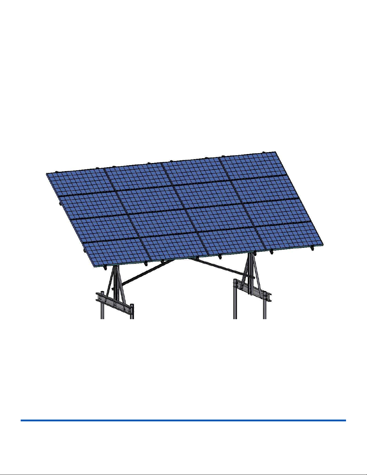
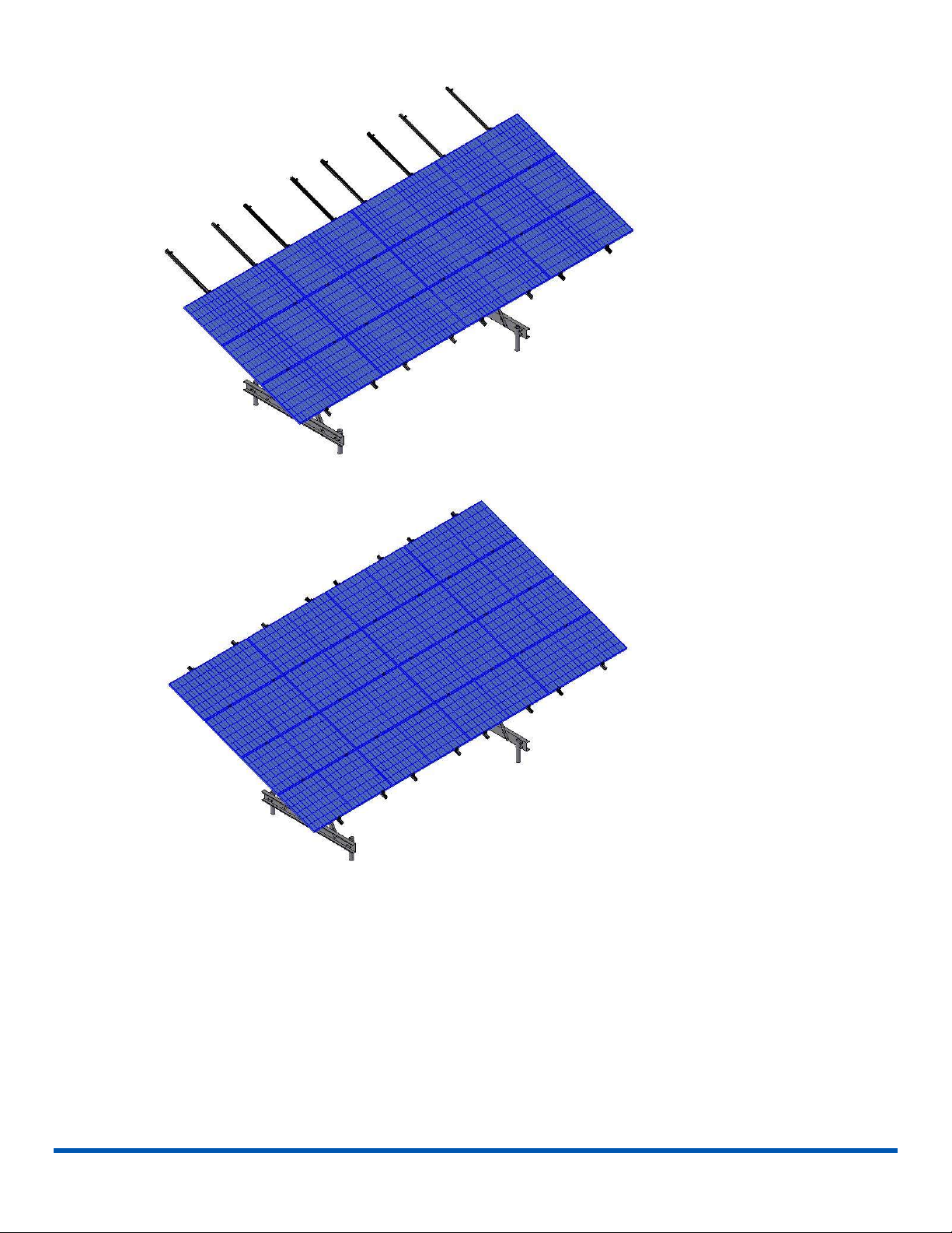
The Pion Power PVSolver Adjustable Ground Mount Solar Racking System can be installed on either helical pile
foundations or cast/ballasted concrete foundations. This installation manual covers only the most basic preparation
steps for helical pile and ballasted concrete foundations.
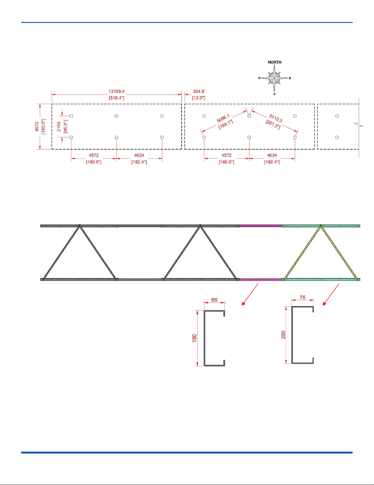
For helical pile foundations, ensure that the helical piles have been installed as per the layout diagram. Drive piles as
accurately as is practical, then adjust to +/- ¼” of given layout. Piles need to be perpendicular to the ground. Top of
piles to be close to level approx. 20” above highest grade. The distance between solar units will vary depending on
the type of solar modules used.
For ballasted concrete foundations, use concrete anchors to connect the T-Beam Footings to the bottom of the
concrete ballasts. Mark the placement locations as per the helical pile layout diagram. Ensure the pile of the T-beam
footing sits right above the marking points.

Racking System Installation Manual, July 12, 2021
© 2021 Pion Power Inc. All Rights Reserved. Page 7
4.3.2 STEP-2:
Start building the table which is at the highest ground, ensure all Bottom Beams of the other tables are at a similar
elevation to avoid shading. Attach the Bottom Beams to the helical piles or piles of the T Beam Footing using U-
bolts and Saddles. A spirit level tool may be helpful when installing the beams. You may use the Rail or a long and
straight object to horizontally level multiple the Bottom Beams.
The two beams should be installed on the outside of the piles, with the flat sides facing toward each other. Ensure
that the angled holes are oriented as in the picture below. Once the beams have been accurately positioned,
tighten the U-bolts using M12 Hex Bolt Sets. Leave 8” of clear space under the Bottom Beam to prevent frost heave
from pushing up on the beams.
Ensure these holes angles up and
toward each other
Ensure the two beams are
installed on the outside of the
piles and leveled at the same
elevation
M12-Hex Bolt Set

Racking System Installation Manual, July 12, 2021
© 2021 Pion Power Inc. All Rights Reserved. Page 8
4.3.3 STEP-3:
Attach the Posts to the Bottom Beams using the M16 Helix Bolt Sets as shown. Ensuring the flat sides of the Posts
go on the flat sides of the Bottom Beams. Do not tighten the bolts until the Post Supports (next step) have been
installed with all their bolts loosely installed.
4.3.4 STEP-4:
Install the left and right Supports as shown using the M12 Helix Bolts Sets. Use a spirit level tool to ensure the Posts
are vertical then tighten all bolts on the Posts and Supports.
M16x50 Hex Bolt Sets
M12x40 Hex Bolt Sets
Base Rail
Racking System Installation Manual, July 12, 2021
© 2021 Pion Power Inc. All Rights Reserved. Page 9
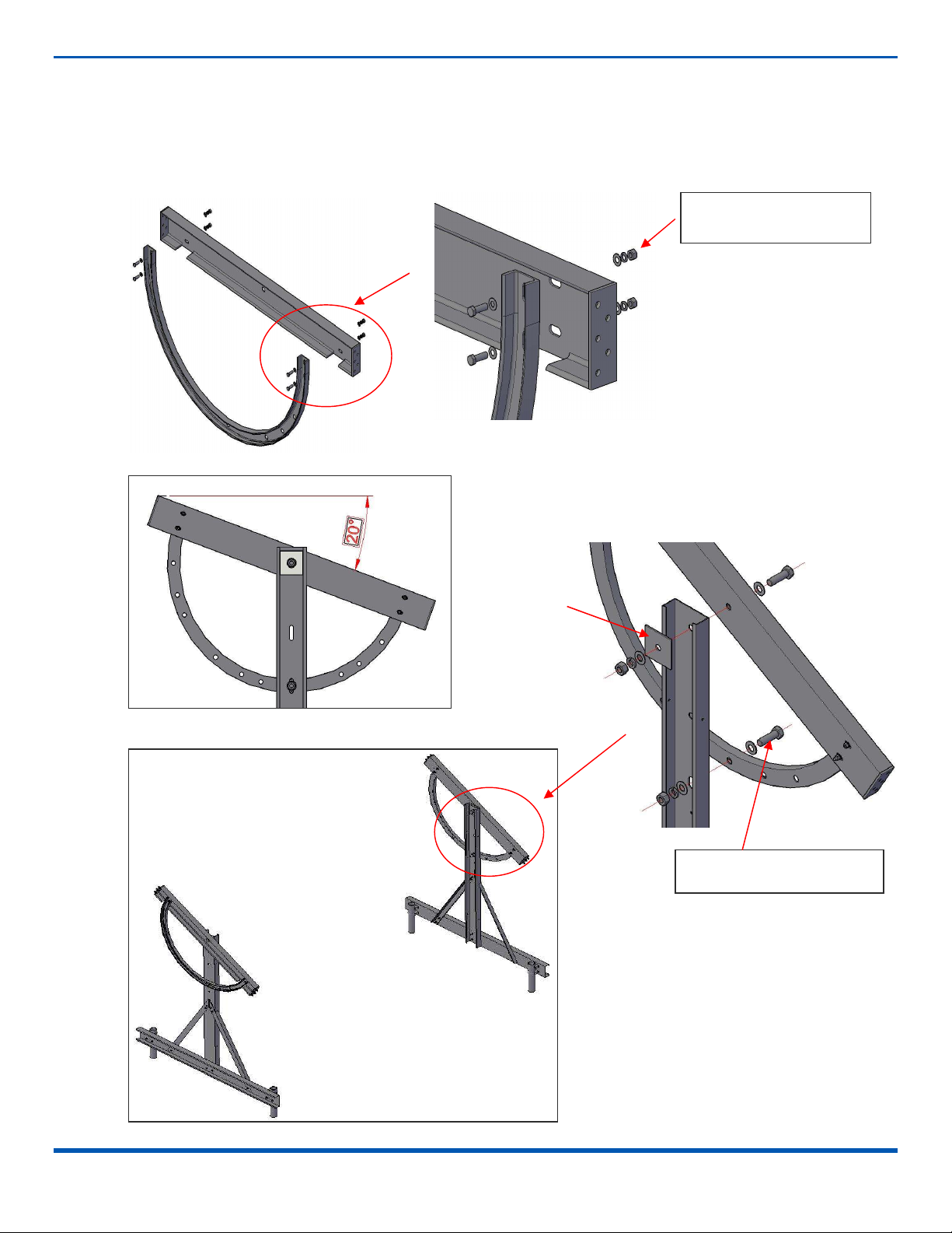
4.3.5 STEP-5:
Attach the Angle Pieces to the Main Beams forming two pivot plates using M16 Hex Bolt Sets. Fix the pivot plates to the Posts using
the Stiffeners and M30 Hex Bolt Sets. The plates need to be able to pivot easily around the top bolt, so do not over-tighten the top
bolts. Move the pivot plates to the “Summer Position” by rotating the plate until the top flange is at 20-degree angle then tighten
the bottom bolt.
M16x50 Hex Bolt Sets
M30x80 Hex Bolt Sets
Stiffener

Racking System Installation Manual, July 12, 2021
© 2021 Pion Power Inc. All Rights Reserved. Page 10
4.3.6 STEP-6:
Each rail consists of two outer pieces and one inner piece. Slide rails together to where holes match up, then tighten all bolts,
washers, and nuts.
M12x40 Hex Bolt Sets

Racking System Installation Manual, July 12, 2021
© 2021 Pion Power Inc. All Rights Reserved. Page 11
4.3.7 STEP-7:
Install the Rails to the pivot plates. Ensure that the flat sides of the Rails go on the Main Beams. Loosely attach the M12 bolts on
one end, then lift the other end and install all remaining bolts. Do not fasten the bolts until both Rails are in place. Once all bolts are
in place, you may finish tightening them.
4.3.8 STEP-8:
Refer to page 12, fix the Tie Bars on the Rails. Tighten the Brace on the north Rail first and then tighten the Brace on the south
Rail.
M12x40 Hex Bolt Sets
M12x40 Hex Bolt Sets
Racking System Installation Manual, July 12, 2021
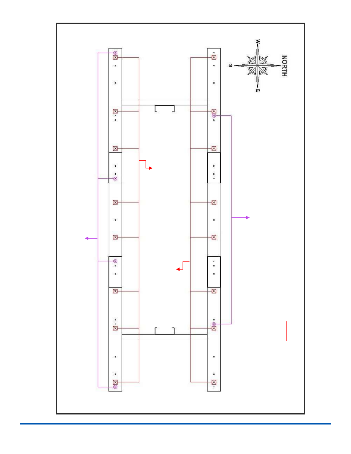
© 2021 Pion Power Inc. All Rights Reserved. Page 12
Two Straps at each of these locations
One Strap end attaches at each of these locations
Module Rail
Module Rail
NOTE:
Top View- not to scale
Strap Brace and Module Rail
Location Diagram

Racking System Installation Manual, July 12, 2021
© 2021 Pion Power Inc. All Rights Reserved. Page 13
4.3.9 STEP-9:
Install the Post Braces on the Posts as shown using M10 Socket Screw Sets.
4.3.10 STEP-10:
Refer to Appendix A for installation of Module Rails. The mounting points varies depend on the type of solar module are using. A
16-module table needs 8 Modules Rails.
M10x30Socket
Screw Sets
Module Rail
4-M10x30 Socket Screw
Sets
Racking System Installation Manual, July 12, 2021
© 2021 Pion Power Inc. All Rights Reserved. Page 14
1 2 3 4 5 6 7 8

Racking System Installation Manual, July 12, 2021
© 2021 Pion Power Inc. All Rights Reserved. Page 15
4.3.11 STEP-11(OPTIONAL):
Install the optional Straining Beams if the system is being installed at a high wind location. The Straining Beams need to be
installed on the North side of the table to provide proper high wind support.
Note: The Straining Beams have a left and a right piece. They must be at their own locations.
2-M30x80 Hex Bolt Sets
Straining Beam

Racking System Installation Manual, July 12, 2021
© 2021 Pion Power Inc. All Rights Reserved. Page 16
4.3.12 STEP-12:
Install the Adjustable Module Clamps as shown. Insert the channel nut into the Module Rail and turn 90 degrees to secure the
clamps, then tighten the Module Clamps.
Please refer to Appendix A before installing the modules. Look for the module model that will be used or comparable modules with
same dimensions. If you cannot find the module model you are installing, please contact your distributor for help.
Mark the mounting points for End Clamps at the bottom (south) row, use a spirit level tool and a thread to ensure all modules will
be installed leveled. Start installing the first module from the far left or far right then moving towards the other end.
Module Rail
End Clamp
Channel Nut
Module Rail
Mid Clamp
Channel Nut

Racking System Installation Manual, July 12, 2021
© 2021 Pion Power Inc. All Rights Reserved. Page 17
Insert the first module into place at the left end of the rack.
The panel should be in landscape position.

Racking System Installation Manual, July 12, 2021
© 2021 Pion Power Inc. All Rights Reserved. Page 18
Suggestions:
1. Turn the table to 70° (winter position) when installing the south two rows of panels;
2. Once the second row of panels is installed, use straps and pullies to pull the system into the “Summer Position”
and secure it with a bolt in the summer position.
3. If you have access to a manlift, it’s best to keep the rack in the winter position as you install the panels. Install the solar panels
row by row.
Racking System Installation Manual, July 12, 2021
© 2021 Pion Power Inc. All Rights Reserved. Page 19
Racking System Installation Manual, July 12, 2021
© 2021 Pion Power Inc. All Rights Reserved. Page 20
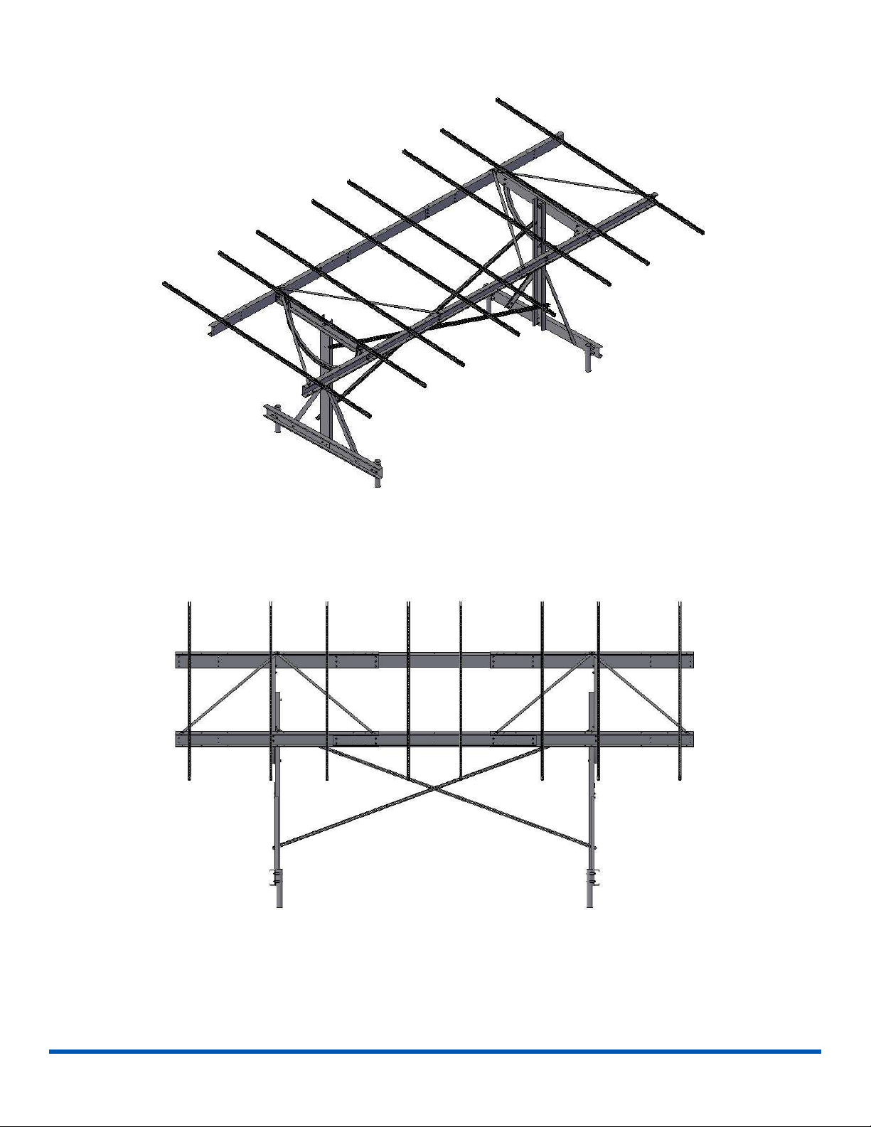
4.3.13 REMARK
The table could also be expanded to accommodate a 24-modules setup.
1. Changes to helical pier layout when installing 24 modules:
2. Please refer to the below illustration for expanding the table to 24-module setup
Please refer to step 6 for installing additional Rails
Please refer to step 8 for installing additional Tie Bars
Table of contents
Popular Solar Panel manuals by other brands


Torqeedo
Torqeedo Sunfold 60 operating manual

Hanplast
Hanplast SW Premium Plus Product documentation

Trina Solar
Trina Solar DUOMAX Series installation manual

LG
LG LG A1C-V5 Series installation manual

solarwatt
solarwatt Vision 60P style Packaging guide

Heckert Solar
Heckert Solar NeMo 4.1 80 M Installation and operating manual


