manuals.online logo
Brands
  1. Home
  2. •
  3. Brands
  4. •
  5. Bluezone
  6. •
  7. Air Cleaner
  8. •
  9. Bluezone PK-220 Setup guide

Bluezone PK-220 Setup guide

Bluezone Products, Inc. 225 Wildwood Ave, Woburn, MA 01801
www.Bluezonefresh.com ● support@bluezonefresh.com ●781-937-0202
Bluezone® PK-220
Air Purification System
Installation, Operation and Service
Manual
Document #: BPI-PM013-00
1
IMPORTANT SAFEGUARDS
READ AND SAVE THESE INSTRUCTIONS
Safety
This manual contains important instructions
and safety information about the Bluezone Air
Purification System. Observe the following
dangers, warnings, cautions and notices
when installing, operating and servicing the
Bluezone PK-220.
Electrical System
Energized electrical circuits present a
potentially life-threatening hazard.
Ensure the unit’s power cord is unplugged
before performing any installation or service
work.
Do Not Operate unit with a damaged cord or
plug. Discard the cord and reorder a new
cord from an authorized Bluezone dealer.
Follow all lockout/tagout procedures for all
electrical circuits.
Refer to the product asset tag and confirm the
PK-220 electrical requirements before
energizing the unit.
System Operation
The appliance is not to be used by persons
(including children) with reduced physical,
sensory or mental capabilities, or lack of
experience and knowledge, unless they have
been given supervision or instruction.
Children being supervised should not play
with the appliance.
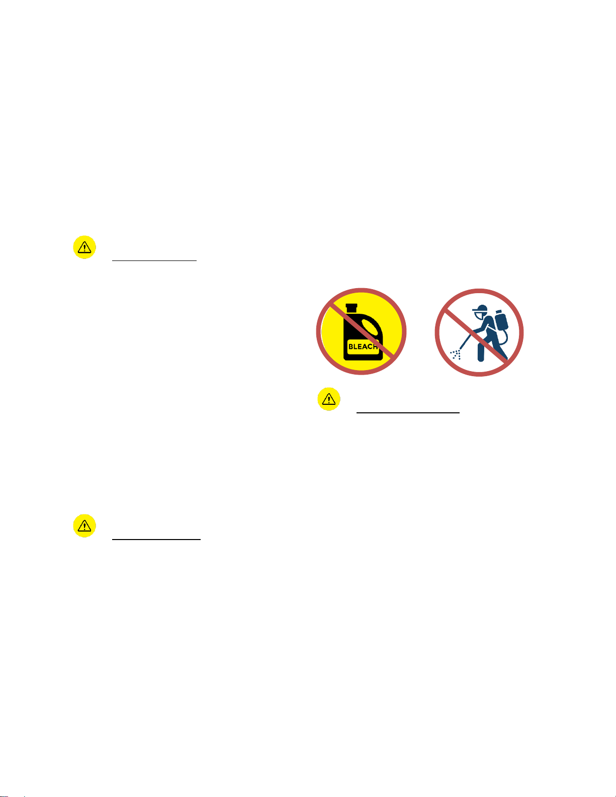
For Indoor Agricultural Applications:
Do not operate the Bluezone PK-220 while
fogging with chlorine bleach or other
disinfectant solutions. Turn off the Bluezone
Units if disinfectant fogging or cleaning is
underway.
•Turn Bluezone units back on after
disinfectants have dissipated.
Never hose down the Bluezone PK-220 or
clean with a water jet.
Turn off Bluezone units and cover with plastic
if the room is being hosed with water or
steam.
System Maintenance
The Bluezone PK-220 contains 4 germicidal
ultra-violet (UV-C) light bulbs; the UV light is
completely contained inside the unit during
operation.
The Bluezone PK-220 has multiple safety
systems to ensure that you cannot view the
UV bulbs while they are operating.
Do NOT attempt to override the cover switch
to allow the bulbs to operate when the cover
is off.
Skin or eye damage may result from directly
viewing the light produced by the lamp in this
apparatus. Always disconnect power before
relamping or servicing.
Replace lamps using Lamp Replacement Kit
Model No. 005-000008, manufactured by
Document #: BPI-PM013-00
2
Bluezone Products Inc. and sold by an
Authorized Bluezone Partner.
The UV-C bulbs contain small amounts of
mercury. If you break a bulb follow the clean-
up instructions at the end of this manual.
Description
The Bluezone® PK-220 is an air purification
device that draws in air containing viruses,
old, spores or fungus, and discharges air with
a highly reduced concentration of these
infectious impurities. The unit is completely
self-contained. The facility, equipment, and
personnel have no contact with the process
that is cleaning the air.
The Bluezone unit’s operation is controlled by
a microprocessor-based controller that alerts
the user to any system faults.
Specifications
The specifications of the Bluezone PK-220 are shown in Table 1. Please note that the 120V and
230V models of the PK-220 are different units and can only be used at the voltage listed on the
asset tag.
Table 1: Bluezone PK-220 Specifications
Imperial / US Installation
Metric / OUS Installation
Size
24 X 48 X 9 in
61 X 122 X 23 cm
Weight
38 lbs.
17 kg
Electrical Current
2A
1.1A
Input Voltage
120V
230-240V~
Power
250 Watts
250 Watts
Flow Rate
220 CFM
380 m3/hr
Mounting Options
Floor, wall, or drop ceiling
Noise
High Speed: 46 dBA
Low Speed: <40 dBA
High Speed: 46 dBA
Low Speed: <40 dBA
Capacity
1600 sf @ 1 ACH
800 sf @ 2 ACH
550 sf @ 3 ACH
150 m2sf @ 1 ACH
75 m2sf @ 2 ACH
50 m2sf @ 3 ACH
Maintenance
Bulb change once every 1-3 years*, no filters to replace
*Bulb life is 8800 hours:
Typical office application is 10 hours per day, 5 days per week, or >3
years between bulb change out. 24 hour/day operation requires an
annual bulb change.
Document #: BPI-PM013-00
3
Key Components
Figure 1: Bluezone PK-220 Key Components
Document #: BPI-PM013-00
4
Electrical System
A wiring diagram of the PK-220 is shown in Figure 2.
Figure 2: Wiring Diagram of the PK-220
Document #: BPI-PM013-00
5
Installation Guidelines
The Bluezone PK-220 offers variable
installation options with no additional
cabinetry required. Units can be mounted to
the floor, mounted to the wall, or installed in
2’ X 4’ drop ceiling grid. A mounting cleat is
provided and must be used in all floor and
wall applications to prevent tip.
The number of PK-220s used in the space
depends on the size of the room and the
desired number of additional air changes
per hour (ACH) to be provided by air
cleaning.
For an additional 1 ACH, use one PK-220
for every 1600 square feet of floor space.
For an additional 2 ACH, use one PK-220
for every 800 square feet of floor space.
For an additional 3 ACH, use one PK-220
for every 550 square feet of floor space.
If multiple Bluezone PK-220 units are being
installed in a room, the following are
recommended guidelines for the placement
of the Bluezone units:
1. Distribute the units relatively evenly
throughout the space.
2. Units placed on the floor should be
positioned against a wall to protect
against tipping.
3. If installing in drop ceiling tiles, ensure at
least one ceiling tile between the
Bluezone PK-220 and either a HVAC
diffuser or a light fixture.
Document #: BPI-PM013-00
6
Installation
Bluezone PK-220 can be mounted to the floor, mounted to the wall, or installed into a 2’ X 4’
drop ceiling opening.
Floor/Wall Mounting:
Overview
The Bluezone PK-220 unit can be mounted the floor or mounted to a wall with the cleat
provided. A wall mounting bracket is integral to the unit.
Figure 3: PK-220 Wall Mounting Bracket
Document #: BPI-PM013-00
7
Preparation
Unpack the Bluezone PK-220 and locate the included wall mounting cleat. See arrows in Figure
4 for recommended fastener install locations.
Figure 4: PK-220 Wall Mounting Cleat
Securely fasten the mounting cleat to the wall using the recommended fasteners shown in Table
2. If installing to metal or wood studs the bracket must be secured to 2 studs. It is the installers
responsibility to determine fasteners. All fasteners must be rated for 120lbs or greater.
For floor placement, mount the cleat 41 ½” off the floor. The installation of the wall mounting
cleat is required to prevent the PK-220 from tipping. Failure to secure the PK-220 with the
mounting cleat can result in injury.
Figure 5: Cleat Mounting Height for Floor Placement of the PK-220
Document #: BPI-PM013-00
8
For wall mounting, Bluezone recommends mounting the cleat at 46” or greater off the floor for 4”
or greater of clearance from the base of the PK-220 to the floor. Provide a minimum distance of
6 in from the top of cleat to the ceiling.
Figure 6: Cleat Mount to Wall for Wall Mounting the PK-220
Securely fasten the mounting cleat to the wall using the recommended fasteners shown in Table
2. If installing the cleat onto a stud wall (wood or metal) locate the studs and fasten directly to
them. Follow anchor manufacturer specifications for selecting screws.
Table 2: Recommended Fasteners
Wall type
Fasteners Recommended
Wood studs
4X #8 cabinet screws
Metal studs
4X ¼-20 toggle-style anchors
Concrete
6X M4 expansion shield anchors
with hex bolts
½” Drywall
6X toggle-style anchors
Document #: BPI-PM013-00
9
Hang the PK-220 mounting bracket on the wall mounting cleat. Adjust the Bluezone PK-220 to
center it onto the mounting cleat.
Figure 7: Hang the PK-220 Mounting Bracket on the Mounting Cleat
Document #: BPI-PM013-00
10
Figure 8: PK-220 Floor Mounted
Figure 9: PK-220 Wall Mounted
Document #: BPI-PM013-00
11
Ceiling Mounting:
Overview
The PK-220 is designed with the option to be installed onto a 2’ X 4’ opening in the grid frame of
a standard suspended ceiling with 2’ X 2’ or 2 X 4’ tiles.
Only mount the PK-220 to a properly installed and structurally strong suspended ceiling with
structural members above the ceiling tiles to attach support wires.
NOTE: It is the installer’s responsibility to:
●Determine if the drop ceiling structure is capable of supporting an additional load of 50lbs.
●Assure local building, electrical and safety codes are followed related to the installation of
this equipment.
●Provide electrical hookup cable as determined by an on-site electrician.
●Provide the 12-gauge hanger wire to support both the ceiling grid and the PK-220
Assembly and installation of the PK-220 is a “two-person” job to avoid injury and potential
damage to the unit. The installer could consider a duct lift to raise the PK-220 unit into the
ceiling opening.
Clearances
The PK-220 is inserted into the ceiling opening at an angle and then seated into the ceiling grid
as shown in Figure 11 and Figure 12. Clearance of 18” above the ceiling grid is needed in order
to accommodate the insertion of the unit into the ceiling.
Clearance on the sides of the unit is 12”.
Installer may use judgement to decrease clearance to 0 on one or two sides of the unit if there is
additional head height to maneuver.
Document #: BPI-PM013-00
12
Installation into Ceiling Grid
1. Install the four included Z-brackets onto the PK-220 by removing the back most screws of
the inlet and outlet mufflers and using them to secure the Z-brackets. Orient the Z-brackets
as shown in Figure 10. The Z-brackets are for use with 12-gauge hanger wire.
Figure 10: Secure Z-Brackets to the PK-220
Document #: BPI-PM013-00
13
2. Carefully angle and push assembly through the opening in the ceiling.
Figure 11: Insert the PK-220 Sideways and Upwards into the Ceiling Grid
3. Orient the PK-220 with louver openings facing down and rest the frame on the ledge of the
ceiling grid.
18” of space above the ceiling tiles, and 12” of space on two adjacent sides are needed to
maneuver the PK-220 into place
Figure 12: Turn the PK-220 so the Grilles Face Down and the PK-220 Nests into Ceiling
Grid
4. Attach hanger wire to support both the ceiling grid and the PK-220 as defined by
relevant building codes.
Document #: BPI-PM013-00
14
Mechanical Installation
A drawing showing nominal dimensions of the PK-220 is provided in Figure 13.
Figure 13: Bluezone PK-220 Nominal Dimensions (units in inches)
Document #: BPI-PM013-00
15
Electrical Installation
Refer to the product asset tag and confirm the PK-220 electrical requirements before energizing
the unit
For wall mount or floor mount installation:
The Bluezone unit is equipped with a power entry module compatible with the separately
provided 6’ long, IEC C-13 power cord.
Plug the power cord into the power entry module.
Once the PK-220 is secured in the space, plug the cord into the nearest electrical outlet rated to
the voltage on the unit’s Model Label.
Secure the cord.
Warning The power cord is attached to the side of the unit and may be caught and pulled
during activities in the space. Secure the power cord to the shelving, wall or other stable
surface.
For ceiling mount:
1. The electrical installation must be done by a licensed electrician. This installation
must comply with relevant electrical codes.
2. Use a junction box for the power connection above the ceiling tiles.
3. Cut off the plug end of the cord provided to create a pig tail for wiring into the junction
box.
4. Thread the pig tail end of the power cable into the junction box through the opening.
Document #: BPI-PM013-00
16
5. Connect the main service to the pig tail in the junction box as shown in Figure 14.
Figure 14: Main Service Connections
6. Attach cover (provided) to junction box.
7. Connect the plug end of the IEC power cable provided to the PK-220 power entry
module.
Document #: BPI-PM013-00
17
Operation
Once the PK-220 is mounted and powered, it can be turned ‘On’ using the on/off switch.
Normal Operation
Once the Bluezone is switched “On”, the Display Screen indicates “Bluezone PK-220” in white
text on a blue background.
The bottom line of the display screen confirms bulb operation, a remaining bulb-life counter and
fan setting.
The Bluezone Logo Status Panel on the front of the PK-220 confirms unit operation and indicate
when to order/replace the bulbs.
High/Low Speed:
The Bluezone PK-220 has two fan speeds: high and low. Press the speed control button once to
change fan speed. (The same button is used to reset the bulb counter when bulbs are serviced).
For more information on the use of the button for bulb-counter reset please refer to the Service
Section.
Document #: BPI-PM013-00
18
Figure 15: Display Sequence in Time
Document #: BPI-PM013-00
19
Warnings, Fault Conditions and Fault Codes
If there are issues with the operation of the PK-220, the Bluezone Logo Status Panel will
indicate the nature of the problem.
Operation status is indicated by the color of the Logo Status Panel defined in Table 3.
Table 3: Bluezone Operating Status
Color
Meaning
Steady Blue
Operating Properly
Flashing Blue
(5 second on,
5 seconds off)
Order new bulbs immediately
Red
Bulbs have reached end of life and must be
replaced.
or
Operating error
Off
PK-220 is off
or
Front Panel is open
More detailed information about operating conditions are displayed on the display panel on the
side of the unit. To see this display on a ceiling mounted unit, a person must use a ladder and
lift a ceiling tile beside the unit. Fault codes and detailed operating conditions shown on the
display are described in Table 4.
Table 4: Display Screen Status Indicator Fault Codes
Display Text
Fault
Operation
Action to Take
Interlock Open
Front Panel Open
Unit automatically
powered down.
Close Front Panel
Fan Fault
Fan not rotating
Unit automatically
powered down.
Contact Bluezone
Fault: Bulbs #-#
Bulbs not operating
Unit automatically
powered down.
Contact Bluezone

Other Bluezone Air Cleaner manuals

Bluezone Model 420 Setup guide

Bluezone

Bluezone Model 420 Setup guide

Bluezone 2400 Setup guide

Bluezone

Bluezone 2400 Setup guide

Bluezone 420 Series Setup guide

Bluezone

Bluezone 420 Series Setup guide

Bluezone 450 Setup guide

Bluezone

Bluezone 450 Setup guide

Popular Air Cleaner manuals by other brands

Amaircare 3050 instruction manual

Amaircare

Amaircare 3050 instruction manual

Rehau BREATHE 1 user manual

Rehau

Rehau BREATHE 1 user manual

Honeywell HFD-120 Series user manual

Honeywell

Honeywell HFD-120 Series user manual

Sharper Image Sharper Image 202441 instruction manual

Sharper Image

Sharper Image Sharper Image 202441 instruction manual

Aerus Air Scrubber owner's manual

Aerus

Aerus Air Scrubber owner's manual

Therapure 201M owner's guide

Therapure

Therapure 201M owner's guide

GILMAN Gemini GAP12 manual

GILMAN

GILMAN Gemini GAP12 manual

ETS AP-160 operating instructions

ETS

ETS AP-160 operating instructions

Winix NK105 user manual

Winix

Winix NK105 user manual

SMC Networks AC20 Series Operation manual

SMC Networks

SMC Networks AC20 Series Operation manual

Winix NK305 user manual

Winix

Winix NK305 user manual

Ravanson MAC-12000 user manual

Ravanson

Ravanson MAC-12000 user manual

Dynamic RS4 Installation instructions & consumer information

Dynamic

Dynamic RS4 Installation instructions & consumer information

Samsung AX70J7100WT Series user manual

Samsung

Samsung AX70J7100WT Series user manual

Stadler Form Viktor operating instructions

Stadler Form

Stadler Form Viktor operating instructions

Muonio UV-O installation manual

Muonio

Muonio UV-O installation manual

Winix PlasmaWave WACU300 Use and care guide

Winix

Winix PlasmaWave WACU300 Use and care guide

Plasma Ions PS-501TR quick start guide

Plasma Ions

Plasma Ions PS-501TR quick start guide

manuals.online logo
manuals.online logoBrands
  • About & Mission
  • Contact us
  • Privacy Policy
  • Terms and Conditions

Copyright 2025 Manuals.Online. All Rights Reserved.