Bluff YARDRAMP User manual

1
YARDRAMP®MODEL WITH CASTERS
Owner’s Manual
Page Contents
2 .........................................Instructions for Unloading Yard Ramps
3 .........................................Yard Ramp Leg Assembly
4–6 ......................................Yard Ramp Operating Instructions
6..........................................Yard Ramp Maintenance
7..........................................Warranty and Returned Goods Authorization
DO NOT SHIP YARD RAMP
ON ITS BOTTOM OR ON ITS TOP
SHIP AND RECEIVE UNIT
ONLY ON ITS SIDE
11-2012
2
INSTRUCTIONS FOR UNLOADING YARD RAMPS
FROM FLATBED TRAILERS
If an overhead crane of sufcient capacity is not available, use a forklift with a minimum capacity rating
of 8,000 pounds to unload catalog listed yard ramps. Customers who purchase custom size yard ramps
which exceed the catalog sizes in width, length or rated capacity should seek a recommendation from Bluff
Manufacturing for forklift capacity due to additional weight.
A nylon sling of at least 48" in length is recommended. The sling may be of the “2 eye” or “endless”
conguration. A minimum capacity rating of 10,000 pounds for the basket method of lifting is recommended.
To lower the yard ramp onto its belly:
1. Create a solid stack of cement blocks or pallets that can hold the weight of the yard ramp during
assembly. This stack needs to be at least 48” high for installing the legs, and be able to support up to
8,000# for standard yard ramps of up to 30,000# capacity and 84” wide.
2. Position the forklift on the underside of the yard ramp. Attach sling as described above.
3. Lift the yard ramp by the sling and lower the yard ramp until the edge of the lip (the end with the chains)
rests on the solid stack created in #1 above.
4. Continue lowering the ramp until the opposite end touches the ground.
5. Tilt the forks back fully and move slowly away from the yard ramp, lowering the forks at the same time.
Continue moving and lowering the forks until the ramp is resting on its belly, the front apron resting rmly
on the solid stack.
6. BEFORE ATTACHING LEGS, MAKE SURE THAT YOU ENGAGE A SECONDARY FAILSAFE
SYSTEM FOR SUPPORTING THE YARDRAMP WHILE YOU INSTALL THE LEGS. THIS CAN
CONSIST OF pallets or wood blocks that stack up to a minimum of 48”, OR A FORKLIFT OR
FORKLIFT WITH SLING THAT IS RATED FOR THE WEIGHT OF THE YARDRAMP.
Additional information on slings and hitches can be supplied by sling providers.
Continued on next page ...
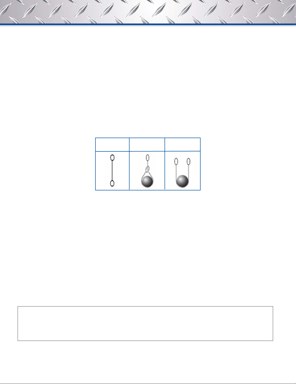
Vertical
Hitch
Choker
Hitch
Basket
Hitch
3
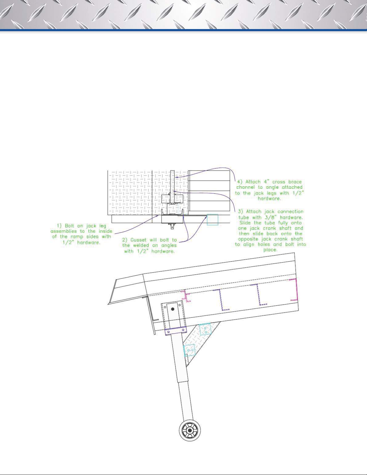
YARD RAMP LEG ASSEMBLY
You should receive the yard ramp with the legs and hardware on a separate pallet.
1. Bolt on jack leg assemblies to the inside of the ramp sides with ½” x 1 ½ hex bolt and hex nut.
2. Gusset will bolt to the welded on angles with ½” x 1 ½” hex bolt and hex nut.
3. Attach jack connection tube with 3/8” x 2” hex bolt and hex nut. Slide the tube fully onto one jack crank
shaft and then slide back onto the opposite jack crank shaft to align holes and bolt into place.
4. Attach 4” cross brace channel to angle attached to the jack legs with ½” x 1 ½” hex bolt and hex nut.

4
YARD RAMP OPERATING INSTRUCTIONS
Balance
Wheels are located at the opposite end as the ramp clamp hole for ease of operation and to make the yard
ramp trail properly when being towed. The balance will shift as the yard ramp is elevated.
Towing
The towing speed will be governed by prevailing conditions, but should not be such as to cause severe
jostling. Towing speeds should not exceed 4 mph. The ramp clamp is intended for short towing distances and
precise positioning of yard ramp units. Over-the-road towing is limited by governing state and federal laws, but
we do not recommend it.
ALWAYS TOW YARD RAMP WITH THE LEGS ALL THE WAY UP AND THE YARD RAMP IN ITS
LOWEST POSITION
NEVER USE RAMP WITH LEGS EXTENDED. RAMP SHOULD ALWAYS SIT FIRMLY ON FRONT &
REAR APRONS DURING USE.
ALWAYS USE THE YARD RAMP WITH THE WHEELS RAISED OFF THE GROUND.
Raising and Lowering the Yard Ramp
To lower or raise the wheels, insert the handle into the crank shaft at the head of the leg, and push until gear is
engaged. Turn lever to raise or lower the wheels. The ramp can be adjusted from either side.
Positioning
To position the yard ramp, ALWAYS MOVE THE YARD RAMP TO THE TRUCK. DO NOT MOVE THE TRUCK
UNDER THE YARD RAMP.
Position the yard ramp so that the front lip is over the surface on which it is to rest with the stop plates resting
against the end of trailer or face of dock.
DO NOT BACK TRUCKS UP TO AND UNDER LIP OF YARD RAMP.
Always move the yard ramp to the truck.
Continued on next page ...
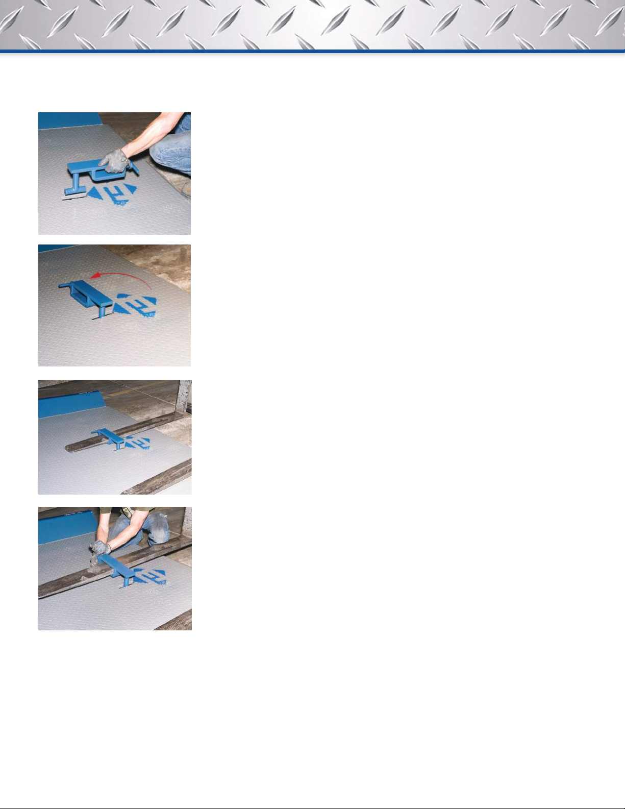
Ramp Clamp
5
5. By gently moving the forklift in the ramp clamp, position the yard ramp close to the dock, trailer or railcar.
6. Raise the lip of the yard ramp with the hand crank so that it clears the surface of to the dock, trailer, or
portable dock. Yard ramps are recommended for use with railcars only if it can be placed properly on the
oor of the railcar and secured with the chains provided.
7. Roll the yard ramp toward the surface that it will be used to bridge. Make sure that the lip of the yard
ramp is all the way over the surface. If a trailer or rail car is end loaded, at least 6” of the lip must rest on
the bed. As soon as the end load has been taken off, the yard ramp should be repositioned so that all 16”
of lip are supporting the yard ramp.
Continued on next page ...
1. With the wheels raised (and the yard ramp
in its lowest position), grasp the Bluff Ramp
Clamp and insert “T” into slot as indicated.
2. Rotate in position as shown. Loosen the Ramp
Clamp screw enough to allow ample room to
insert fork.
3. Drive fork lift forward slowly to insert fork into Ramp
Clamp. Once in position, raise forks enough to
allow tightening of Ramp Clamp screw
4. Bluff Yard Ramp can now be positioned with
fork lift.

6
8. Using the hand crank, lower the yard ramp until the lip of the yard ramp is fully engaged on the trailer.
Continue raising the wheels until a minimum of 2” inches are clear between the ground and the caster.
This insures that as you load or unload the vehicle, the yard ramp will never rest on the wheels.
9. Attach the safety chains found on the front of the yard ramp to the vehicle being loaded/unloaded to
assure that the yard ramp will not pull away. If the yard ramp is end loaded and there is only a minimum of
the lip on the surface of the vehicle, be sure to use the chains to secure the ramp initially, and then when
more of the lip can be placed on the vehicle, re-tighten the securing chains.
10. Reverse steps 1 to 9 to disengage ramp.
REMEMBER: THE WHEELS ARE NOT DESIGNED TO CARRY ANY LOAD.
Securing
For safety, always secure the yard ramp in place utilizing the two safety chains located on the front of the
yard ramp. Chains should be looped around a sturdy part of the trailer, platform, or dock on which the yard
ramp is resting, using the grab hooks to complete the loop. The chains should be as tight and as horizontal as
possible, but allow for change in vehicle height caused by shifting loads.
Using
Vehicles traversing the yard ramp should always maintain a slow, steady speed, preferably in low gear. They
should not stop or change gears while on the yard ramp, as this may cause excessive wear and damage to the
vehicle tires.
Forklift trucks should ascend and descend with their forks tilted back and raised enough to avoid contact with
the yard ramp deck.
Storage
When nished using yard ramp:
1. Release the safety chains and place them securely on deck of yard ramp.
2. Crank legs to lift up the ramp.
3. Roll yard ramp away from platform, dock, or vehicle. Trucks may be driven away from the
yard ramp but not before steps 1 and 2 above have been performed.
4. Lower yard ramp to stored position.
YARD RAMP MAINTENANCE
Lubrication
The legs and casters have grease pins that should be greased every 6 months. Lubricate wheel hubs with
waterproof automotive grease by using standard "zert" grease gun.
Structure
Welded yard ramp structure should be inspected at least annually (or more often, according to usage) for
evidence of damage, including but not limited to cracks/failures in materials or welds.
Steel work should be repainted as required.
Continued on next page ...

7
BLUFF WARRANTY
Bluff Manufacturing warrants their products to be free from defects in material and workmanship for a period of
one year from shipping date to original purchaser. Yard ramp pumps and EOD hydraulic power units are war-
rantied for 90 days from shipping date to original purchaser. Warranty eligibility requires all products are used
and serviced in accordance with the company’s recommendations, product selection guides, product manuals
and installation instructions.
Bluff Manufacturing’s obligation under this warranty shall be limited to the repair, by Bluff Manufacturing or a
Bluff Manufacturing authorized technician, or exchange of any part or parts which may prove defective un-
der normal service within the time limitations set forth above, and which our examination shall disclose to our
satisfaction to be defective. Bluff Manufacturing requires the purchaser to send date stamped photographs for
initial review of warranty claim products.
This limited warranty does not cover any defects, malfunction or failure caused by or resulting from improper
or unauthorized service, maintenance, installation, repair or use not in conformance or accordance with Bluff
Manufacturing’s recommendations, product selection guides, product manuals or installation instructions and
the intended use and capacities or specications or from abuse, neglect, accident, weather related issues
or any other cause beyond the control of Bluff Manufacturing This limited warranty is made only to the origi-
nal purchaser, which shall be deemed to mean that person or organization to which the product is originally
shipped or installed.
Bluff Manufacturing does not approve nor authorize any other person or entity to obligate Bluff Manufacturing
to any other liability not described herein concerning the sale of its products.
Bluff Manufacturing shall not be liable for any incidental or consequential damages. And liability hereunder is
expressly limited to repair or replacement of any part or parts which may prove defective within the time pre-
scribed hereon.
This warranty is expressly in lieu of all other warranties, expressed or implied, including the warranties of mer-
chantability and tness for a particular purpose and all other obligations or liabilities on our part.
BLUFF RETURNED GOODS AUTHORIZATION (RGA)
Before returning any merchandise for any reason whatsoever, it is necessary to contact Bluff Manufacturing for
approval. All requests must be submitted with a date stamped photograph of item to be returned. If approval is
given, an RGA number will be given by Bluff Manufacturing. This RGA number must appear on all documents
involving the returned goods.
Freight charges on all RGA’s must be PREPAID on returns but not warranties.
RGA numbers will not be issued after ninety (90) days from date of shipment, except for warranty items, by
Bluff Manufacturing or its designated representative.
A restocking charge of 25% will be made on all merchandise except as allowed under warranty claims.
Returns will not be allowed on any custom, special or worksheet required items and products in non-resalable
condition.
Table of contents
Other Bluff Industrial Equipment manuals


