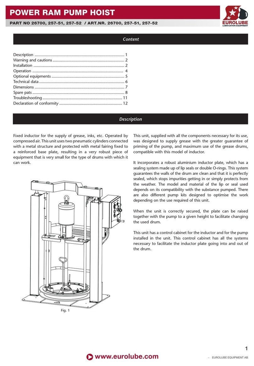
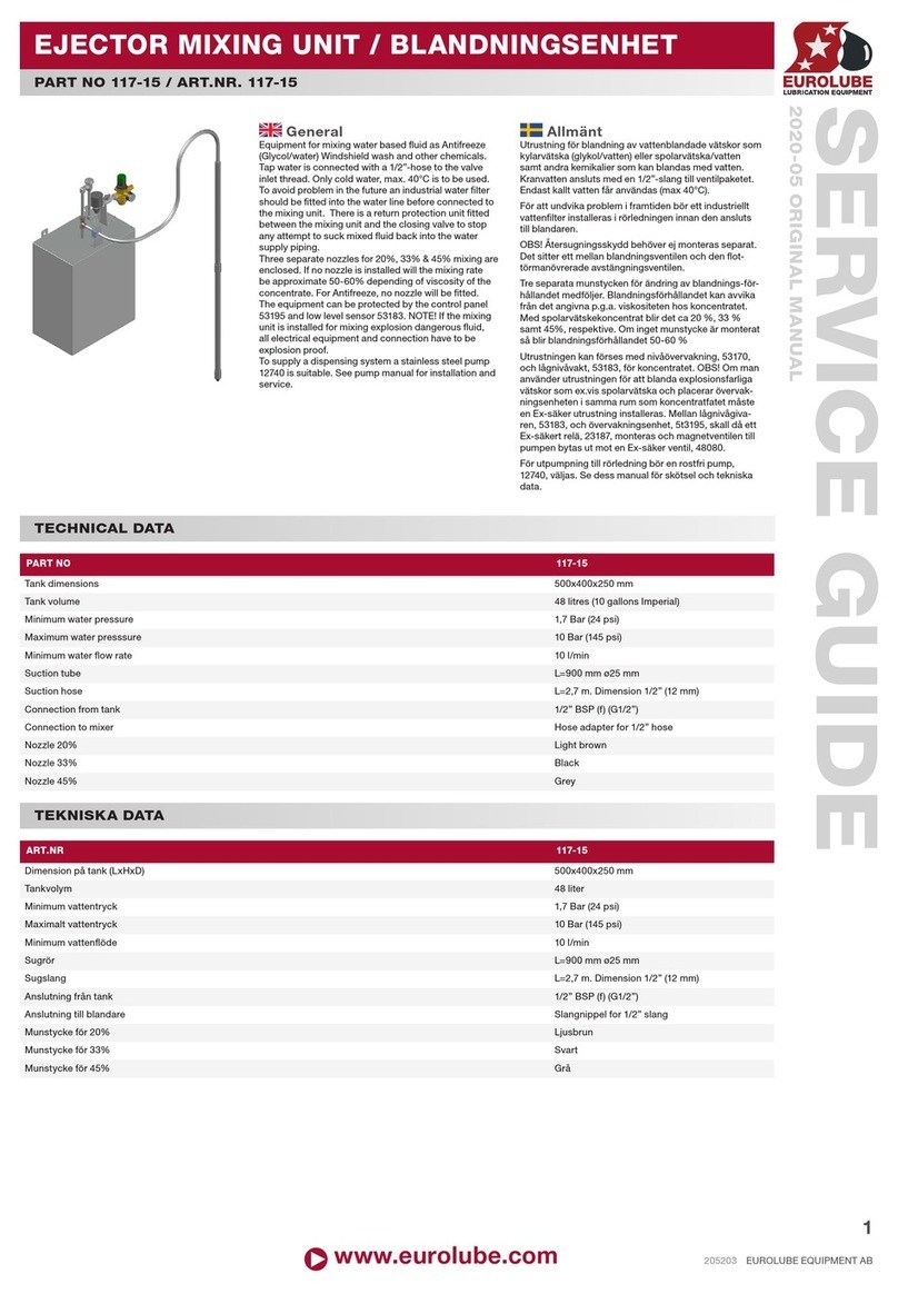
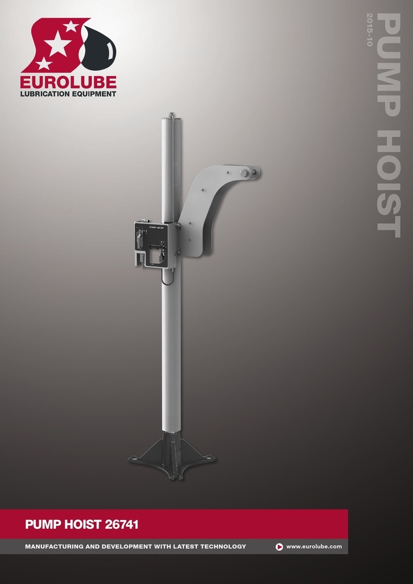
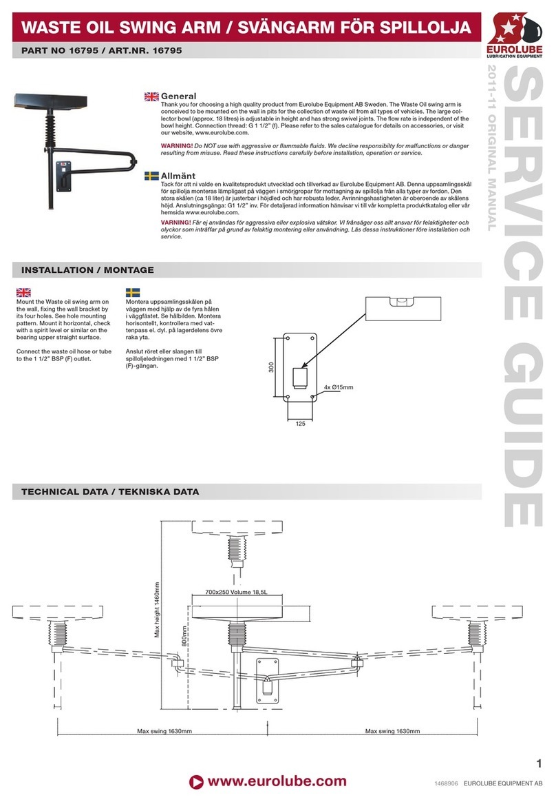
Eurolube 17875 User manual

www.eurolube.com EUROLUBE EQUIPMENT
PART NO 17875 / ART.NR. 17875
SERVICE TOWER FOR TRUCK WORKSHOPS
INSTALLATION GUIDE
2020-03
1
General
The service tower is designed to be equipped with one exhaust hose reel with max 10 m ø150 mm (33ft and ø6”) exhaust
hose and 16 hose reels for uid or air + 2 electrical cable reels. The top is provided with fastening hole which are suitable for
hose reel models T10, T15, S10, S15 and C15. The electrical cable reels which are provided with pivoting bracket can be mounted
under the exhaust reel on each side of the tower. All connections must be done with suitable hoses from the bottom and up to the
bulkhead in upper end of the tower. The hoses have to withstand the uid and pressure which will be delivered through them. If the
tower is to be equipped with one extra exhaust hose reel, a separate support sheet metal part must be added on the top and at the
opposite side of the rst exhaust reel. Extra support beams on top of the tower, are also required. In this case, 14 hose reels can be
mounted (+ 2 electrical cable reels). Some kind of lifting device is needed, for example a fork lift or an overhead crane which have
enough capacity to lift up the assembled top section on top of the lower section.
Allmänt
Servicetornet är tänkt att användas med en upprullare för avgasslang med max 10m Ø150mm avgasslang och 16 slangupprullare
för vätska eller luft plus två kabelupprullare. Övre delen är förberedd med fästhål som passar för slangupprullare T10, T15, S10, S15
och C15. De elektriska kabelupprullarna som levereras med svängbart väggfäste monteras under avgasupprullaren på varsin sida
av tornet. Alla anslutningar måste göras med lämpliga slangar från botten till den övre delen av tornet, och slangarna måste tåla den
vätska och arbetstryck de skall utsättas för. Om tornet skall utrustas med en extra avgasupprullare måste ett extra stöd i stålplåt
monteras på toppen och på motsatt sida av den första avgasupprullaren. Extra stödbalkar på ovansidan av tornet krävs också. Om
man väljer denna lösning kan endast 14 slangupprullare + 2 kabelupprullare monteras. Någon slags lyftanordning krävs för monte-
ring, t.ex. en gaffeltruck eller en travers med tillräcklig kapacitet för att lyfta upp överdelen på den nedre delen.
TECHNICAL DATA / TEKNISKA DATA
DIRECTION OF TOWER / TORNETS RIKTNING
The bottom section of the tower can be mounted in all directions on the
oor frame.
The middle section can be mounted in two directions on the bottom
section.
The top section can be mounted in two directions on the middle section.
Bottendelen av tornet kan monteras i alla riktningar som stöds av
ingjutningsramen.
Mittensektionen kan monteras i två riktningar ovanpå bottendelen.
Taket kan monteras i två riktningar ovanpå mittensektionen.
800
800
3580
1696
1641
581
2341
1200
800

www.eurolube.com
EUROLUBE EQUIPMENT
PART NO 17875 / ART.NR. 17875
SERVICE TOWER FOR TRUCK WORKSHOPS
2
ASSEMBLY OF THE TOP SECTION OF THE TOWER / MONTERING AV DEN ÖVRE DELEN AV TORNET
• Unpack the complete delivered package and control
carefully that all needed parts really are included into
the delivery. If anything is missing or damaged it MUST
immediately be reported back to us for suitable remedy.
• Enclosed are 72 M10x25 bolts and 72 M10 nuts for
the assembly of the tower. There are also 4 M8x20 bolts
to x the loose shutter. The two eye bolts are included
for use when the lower section is lifted off the upper
section.
• Fix the eye bolts on the top of the lower section. Use a
fork lift or similar to lift the bottom section off the upper
section of the tower (Fig 1).
• While the upper section is xed on the EURO pallet,
mount the required number of bulkhead couplings as
indicated in (Fig 2).
• Now mount the meter units and their connections (Fig
3). Make sure they will be absolutely leak proof. If nec-
essary, use a oating sealant (for example Loctite 577).
• Packa upp alla delar i leveransen och kontrollera
noggrannt att alla nödvändiga delar är med. Om något
fattas eller är skadat MÅSTE det rapporteras omedel-
bart till oss.
• Bipackat är 72st M10x25-skruvar samt 72st M10-
muttrar. Även 4st M8x20-skruvar för att skruva fast
luckan. De två lyftöglorna ingår för när nederdelen skall
lyftas bort från överdelen.
• Fäst lyftöglorna i nederdelen, använd en gaffeltruck
eller dylikt för att lyfta bort nederdelen från överdelen
(g 1).
• Medans nederdelen fortfarande är bultad i EURO-
pallen, montera alla skottgenomgångar som krävs enligt
(g 2).
• Montera mätmodulerna och anslutningar (g 3).
Säkerställ att montaget blir helt tätt. Om nödvändigt,
använd ytande tätningsmedel (t.ex Loctite 577).
• (Fig 4) Mount a support rail and equip it with, for
example, ”HYRO” clamps to relieve the meters from
possible force coming from the connected hoses, which
can be very heavy. This to avoid leakage in the future
when the uid pressure will create pulsation and move-
ment in the hoses. How these are mounted depends on
choice of support rail and clamps.
• Now is it time to create the rst connection to the me-
ters and solenoidvalves. Use a suitable electrical cable
(Eurolube’s article no 53393) and make sure that they
are long enough to reach the connection box (MPDM)
without any joint.
• (Fig 4) Montera en stödskena och montera t.ex
HYRO-klammer på slangarna, som kan vara tunga.
Detta för att slangen inte skall hänga i mätmodulen och
orsaka läckage i framtiden när vätsketrycket orsakar
pulsationer och rörelser i slangarna. Hur detta monteras
beror på valet av stödskena och klammer.
• Nu är det dags att börja montera den elektriska
anslutningen till pulsmätaren och magnetventilen
(mätmodulen). Använd lämplig kabel (Eurolube artikelnr
53393 och säkerställ att kabeln är tillräckligt lång för att
nå MPDM:en utan skarvar. Se i det bifogade bladet som
följer med mätmodulen hur denna kopplas in.
FIG. 3
FIG. 4
FIG. 2
1
2
3
4
FIG. 1

www.eurolube.com EUROLUBE EQUIPMENT
PART NO 17875 / ART.NR. 17875
SERVICE TOWER FOR TRUCK WORKSHOPS
3
ASSEMBLY OF THE TOP SECTION OF THE TOWER / MONTERING AV DEN ÖVRE DELEN AV TORNET
• Assemble the three top plates as shown is Fig 5 and tight rmly. • Montera de tre takdelarna enligt g 5 och dra åt ordentligt.
• Make sure the tower is supported and stable
since the next step might require a person on
top of the tower.
• Make sure that the top plate assembly is
placed in right position in reference to the
exhaust hose reel connection. Tight the bolts
rmly so they don’t get loose later when they will
be exposed to heavy force from the hose reels.
• Look on the order or in the separate instruc-
tion which describes what equipment belongs
to respective tower.
• Mount all the hose reels which are intended
to be placed on respective tower. Consider the
balance of the tower when doing this. Mount the
reels alternately on both sides. The exhaust reel
should also be mounted at this time.
• (Fig 7) Connect all hoses from the reels to
respective bulkhead coupling and tighten them
properly to prevent any risk of leakage. Normal
connection is it an adapter with an inner conical
part at 60°. (If necessary use oating sealant as
Loctite 577, never use ax or Teon tape).
• Now the upper part of the service tower is
complete. It can be placed directly on the lower
part if that part is placed on its nal position in
the workshop. Otherwise it will be stored until
the lower part is complete.
• Säkerställ att tornet är fastskruvat och stabilt
då nästa steg kan kräva att en person benner
sig uppe på torntaket.
• Säkerställ att taket vänds åt rätt håll med
tanke på ansluten för avgasupprullarens inlopp.
Dra åt bultarna hårt, torntaket utsätts för starka
påfrestningar när alla slangupprullare är mon-
teras och används.
• Kontrollera mot ordern eller separata instruk-
tioner som beskriver vilken utrustning som skall
monteras i vilket torn.
• Montera alla slangupprullare som hör till
tornet. Tänk på att inte montera alla på en sida
först, utan ta en på motsatt sida i taget. Avgas-
upprullaren kan också monteras vid detta steg.
• (Fig 7) Anslut alla inloppsslangar från slangup-
prullarna till respektive skottgenomgång och
dra åt ordentligt för att undvika läckage. Bäst
anslutning erhålles med en hydraulisk adapter
med 60° tätningskona. (Om det krävs, använd
ytade tätningsmedel t.ex Loctite 577, använd
aldrig lin eller gängtejp.)
• Den övre delen av tornet är nu klart. Den kan
nu monteras direkt på överdelen om denna står
på plats eller ställas undan tills nederdelen är
klar.
1
2
3
4
1
2
3
4
FIG. 5
FIG. 6
5
6
7
FIG. 7A FIG. 7B

PART NO 17875 / ART.NR. 17875
SERVICE TOWER FOR TRUCK WORKSHOPS
EUROLUBE EQUIPMENT
Alentec & Orion AB, Grustagsvägen 4, SE-138 40 Älta, Sweden
www.eurolube.com 4
ASSEMBLY OF LOWER PART OF THE TOWER / MONTERING AV DEN NEDRE DELEN AV TORNET
MOUNTING THE COMPLETE TOWER / SLUTMONTERING AV TORNET
FIG. 9
• Mount the lower parts directly onto the frame which al-
ready has been placed on its right position in the workshop.
• It is assumed that the tower frame already has been
placed on its location and been moulded into the concrete
oor and that the concrete is dry enough to withstand the
forces created from completed service tower.
• Tighten the nuts with suitable torque so they don’t get
loose later when the tower will be exposed to heavy force
and possible vibrations.
Make sure the tower is not leaning in any direction.
• Montera de nedre delarna direkt i den ingjutna ramen som
redan placerats på sin rätta plats i verkstaden.
• Nu antas det att ramen har placerats på plats och gjutits
fast i golvet och att betongen är tillräckligt torr för att klara
krafterna från det monterade servicetornet.
• Dra åt skruvarna med lämpligt moment så att de inte loss-
nar senare när tornet utsätts för stora krafter och möjligtvis
vibrationer.
Säkerställ att den nedre delen inte lutar åt något håll!
• Now is it time to lift the pre mounted upper
part of the tower on to its position.
• Fix the upper part with the enclosed M10x25
screws on top of the lower section. All holes
are pre drilled.
NOTE! The four screws in the
corners should be mounted with the
thread upwards.
• Mount all internal hoses and seal them
against the bulk head or meter, which should
have an inner conical surface at 60°. Connect
the exhaust reel to its tube and connect all
cables from the meters.
• When everything is connected and ready,
mount the loose shutter and place the oor grid
inside the tower.
• Nu är det dags att lyfta upp den förmonterade
övre delen på sin slutgiltiga plats.
• Montera den övre delen på den nedre delen
med de bifogade M10x25-skruvarna. Alla hålen
för förborrade.
OBS! De fyra skruvarna i hörnen
måste monteras med gängan uppåt.
• Montera alla interna slangar och täta dem
mot skottet eller mätmodulerna, vilket skall
göras med hydraulisk 60° kona. Anslut avgas-
upprullaren till dess rör och anslut alla kablar
från mätmodulerna.
• När allt är anslutet och klart, montera luckan
och placera golvgallret.
1
2
3
4
FIG. 8
5
6
7
Other Eurolube Industrial Equipment manuals
Popular Industrial Equipment manuals by other brands
SKF
SKF Linkoln WS-E Series installation instructions

Cembre
Cembre PCM-2P Operation and maintenance manual
DMP Electronics
DMP Electronics SCS-104 installation guide
Schwing
Schwing CPC3 manual
Abicor Binzel
Abicor Binzel CAT3 PRO Operating instruction
CDL
CDL La Fendeuse OPENING PROCEDURE AT BEGINNING OF SEASON AND CLOSING
