Bluff DuraSweeper series Programming manual

(800) 433-2212 •Fax (817) 293-7570
9201 South Freeway • Fort Worth, TX 76140
www.bluffmanufacturing.com
20150422
This manual has been most recently updated:
DuraSweeper®
Snow Removal System
DS-15-A-PORT
DS-15-A-PERM
DS-20-A-PORT
DS-20-A-PERM
OWNER’S MANUAL AND INSTALLATION GUIDE FOR

DuraSweeper®
Contents
Disclaimer ............................................................................................................................................. 1
Copyright............................................................................................................................................... 1
Cautions for Receiving this Product ...................................................................................................... 1
Instructions for Removal of Unit From Truck......................................................................................... 1
DuraSweeper®by Bluff.......................................................................................................................... 2
Warnings ............................................................................................................................................... 2
Safety Precautions ................................................................................................................................ 3
Pre-Operation Hazard ........................................................................................................................... 3
Modication Hazard .............................................................................................................................. 3
Exposure Hazard .................................................................................................................................. 3
Fire Hazard ........................................................................................................................................... 3
Entanglement/Severe Hazard .............................................................................................................. 3
Alcohol and Drug Hazard ..................................................................................................................... 4
Flying Object Hazard ............................................................................................................................ 4
Safety Precautions ............................................................................................................................... 4
DuraSweeper® Specications ............................................................................................................... 6
Product Specications........................................................................................................................... 6
Product Specications........................................................................................................................... 7
Ejected Material and Clear Lane .......................................................................................................... 8
Tools and Equipment............................................................................................................................. 9
Site Location Requirements - Portable Model....................................................................................... 9
Site Location Requirements - Permanent Model................................................................................. 10
Pad Suggestion for Permanent Installation..........................................................................................11
Suggested Concrete Pad Specication - Permanent Model Standard Layout.................................... 12
Suggested Concrete Pad Specication - Permanent Model Non-Standard Layout ............................ 13
Recommended Safety Barrier Equipment .......................................................................................... 14
Power Provisions................................................................................................................................. 14
Parts & Assemblies.............................................................................................................................. 15
Installation On-Site.............................................................................................................................. 16
Pre-erection Assembly......................................................................................................................... 16
Installation Tips.................................................................................................................................... 16
Recommended Tools........................................................................................................................... 17
Installation of the DuraSweeper®by Bluff............................................................................................ 18
Portable Models................................................................................................................................... 24

DuraSweeper®
Permanent Models .............................................................................................................................. 26
Main Panel Switch Locations............................................................................................................... 34
Determine Brush Motor Rotation ........................................................................................................ 34
Proximity Switch Tests......................................................................................................................... 34
Initial Testing........................................................................................................................................ 34
Upper Proximity Switch ....................................................................................................................... 35
Lower Proximity Switch ....................................................................................................................... 35
Automation Test .................................................................................................................................. 35
Standard Operation ............................................................................................................................ 37
Warnings ............................................................................................................................................. 37
Shut Down and Start Up Procedures ................................................................................................. 38
Routine Maintenance........................................................................................................................... 39
Long Term Storage.............................................................................................................................. 40
Removing from Storage....................................................................................................................... 40
Changing The Brush Wafers............................................................................................................... 41
Brush Drive.......................................................................................................................................... 42
Pulley................................................................................................................................................... 43
Hoist Drive........................................................................................................................................... 44
Brush Idler........................................................................................................................................... 45
Carriage Wheel.................................................................................................................................... 46
Electric Cable Carrier .......................................................................................................................... 47
Trouble Shooting................................................................................................................................. 48
Bluff DuraSweeper®Snow Removal System Warranty ...................................................................... 49

1
DuraSweeper®
DuraSweeper®
DISCLAIMER AND COPYRIGHT
Disclaimer
The illustrations used in this manual are intended as representative reference views only. Moreover,
because of our continuous product improvement policy, we may at any time, modify information,
illustrations and/or specications to explain and/or exemplify a product, service or maintenance
improvement. We reserve the right to make any change at any time without notice. DuraSweeper®and
DuraSweeper®, LLC. are all the same entity and are used interchangeably.
DuraSweeper® is the registered trademark of WILLIAM CANDELETTI.
Copyright
© 2015 DuraSweeper®, LLC
DuraSweeper®by Bluff Manufacturing reserves all copyright and other rights in this manual and the
manual’s content. No part of this manual may be reproduced or used in any way without the written
permission of Bluff Manufacturing, except as necessary to operate equipment of DuraSweeper®by Bluff
Manufacturing.
Cautions for Receiving this Product
Please make sure that you receive the entire number of pieces called for on the bill of lading (BOL) and
that they are in good condition before signing the receipt from the freight company. Damage claims will
not be accepted if receipt is signed.
Instructions for Removal of Unit From Truck
The brush carriage assembly should not be lifted by the brush or brush core. For more details, see
INSTALLATION INSTRUCTIONS in this manual.
The electrical enclosure should only be lifted by the lifting eye, which is located at the top of the
enclosure.
Inspect parts and assemblies for any damage from shipment and verify that the parts match the BOL.

2
DuraSweeper®
DuraSweeper®by Bluff
Warnings
This manual provides important information to familiarize you with safe operating and maintenance
procedures. Read and understand this manual before operating the DuraSweeper®by Bluff
Manufacturing and follow its instructions when operating the unit.
LOOK FOR THESE SYMBOLS WHICH POINT OUT ITEMS OF EXTREME IMPORTANCE TO THE
SAFETY OF YOU AND YOUR COWORKERS. READ AND UNDERSTAND THOROUGHLY. HEED
THE WARNING AND FOLLOW THE INSTRUCTIONS.
Keep safety labels in good condition. If safety labels become missing or damaged, replacement safety
labels are available from Bluff Manufacturing at 1-800-433-2212 (see also Safety Label Installation in
Maintenance Section).
Indicates a hazardous situation which, if not avoided, will result in death or serious injury.
Indicates a hazardous situation which, if not avoided, could result in death or serious injury.
Indicates a hazardous situation which, if not avoided, could result in minor or moderate injury.
NOTICE
Indicates a situation which can cause damage to the equipment, personal property and/or the
environment, or cause the DuraSweeper®by Bluff to operate improperly.
NOTE: Indicates a procedure, practice, or condition that should be followed in order for the unit or
component to function in the manner intended.
!DANGER
!WARNING
!CAUTION

3
DuraSweeper®
Safety Precautions
!CAUTION
The safety messages that follow have CAUTION level hazards.
Pre-Operation Hazard
Read and understand this Operation Manual before operating or servicing the DuraSweeper®
by Bluff to ensure that safe operating practices and maintenance procedures are followed.
• Contact Bluff Manufacturing or an authorized DuraSweeper®Dealer for additional training.
• Obtaining any and all necessary licenses to operate the unit is the responsibility of the
purchaser.
!WARNING
The safety messages that follow have WARNING level hazards.
Crush Hazard
Keep bystanders away from work area before and during operation.
Modication Hazard
Never modify the DuraSweeper®by Bluff without written consent of Bluff Manufacturing. Any
modication can affect the safe operation of the unit and may cause personal injury or death.
Modications will also nullify the warranty.
Exposure Hazard
Always wear personal protective equipment, including appropriate clothing, gloves, work
shoes, and eye protection.
• Never operate the DuraSweeper®by Bluff while wearing a headset.
Fire Hazard
Have appropriate safety equipment available. Have all re extinguishers checked periodically
for proper operation and/or readiness.
Entanglement/Severe Hazard
• Verify that all guards and covers are attached properly to the unit before starting the unit. Do
not start the unit if any guards or covers are not properly installed on the unit.
• Verify there are no people, obstacles or other equipment near the DuraSweeper®by Bluff
before starting the unit.

4
DuraSweeper®
Remove all jewelry, tie back long hair and keep hands, other body parts and clothing away
from moving/rotating parts.
Stop the unit before beginning service.
• If you must run the unit during maintenance procedures, make sure to keep bystanders clear
of the unit.
• Attach a Lockout/Tagout with “Do Not Operate” tag on the ON/OFF switch while performing
maintenance on the equipment.
Alcohol and Drug Hazard
Never operate the unit while under the inuence of alcohol or drugs, or when ill or sleepy.
Flying Object Hazard
Always wear eye protection while operating the unit or cleaning the DuraSweeper®with
compressed air or high-pressure water. Dust, ying debris, compressed air, pressurized water
or steam may injure your eyes.
!CAUTION
The safety messages that follow have CAUTION level hazards.
Poor Lighting Hazard
Ensure that the work area is adequately illuminated.
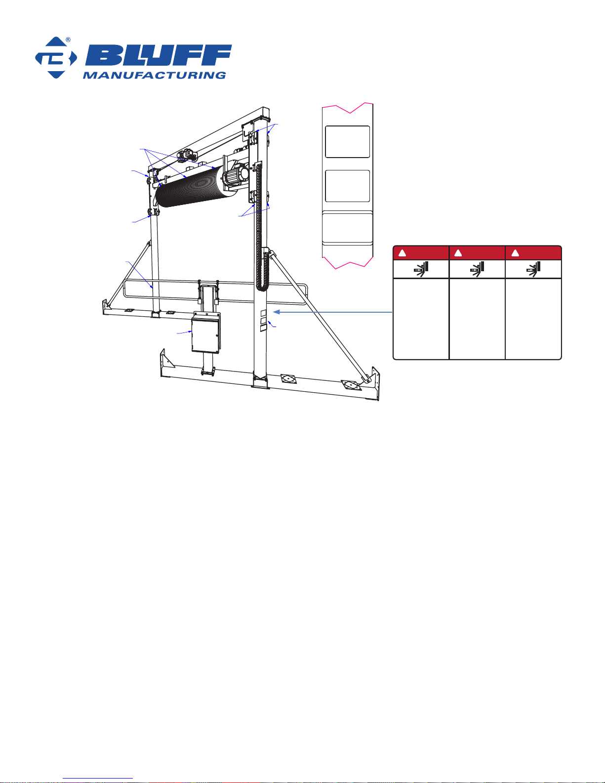
Safety Label Locations
Safety Precautions
If your unit has been renished it is extremely important that all the safety decals be replaced in their
proper locations. The illustrations below will aid you in determining the proper locations.
A description of location is provided for each safety label. For additional instructions, contact your
dealer (see also Safety Label Installation in Maintenance Section).
5
DuraSweeper®
Warning Labels
on Both Columns
A
Warning Label
Location
Warning Label
Location
Illustration for Warning Label Page
file locations:
model - C:\Users\stevebales\Desktop\DuraSweeperManual\Inventor Model 5\DS-PortableStandard.iam
drawing - C:\Users\stevebales\Desktop\DuraSweeperManual\Inventor Model 5\InstallationManualPrints\DS-PortableStandard-SafetyLabels.idw
PDF - C:\Users\stevebales\Desktop\DuraSweeperManual\Inventor Model 5\InstallationManualPrints\DS-PortableStandard-SafetyLabels.pdf
2. Entanglement
Hazard
1. Pinch Hazard
1. Pinch Hazard
1. Pinch
Hazard
1. Pinch Hazard
3. Electricution
Hazard
WARNING
1. PINCH HAZARD! Stay clear of the columns. Failure to comply can result in death or serious injury.
2. ENTANGLEMENT HAZARD! Rotating brush. Keep hands, feet and clothing away. Failure to comply
could result in death or serious injury.
3. ELECTROCUTION HAZARD! Read owner manual before operating equipment.
ADVERTENCIA
1. ¡RIESGO DE SER ESTRUJADO! Mantengase alejado de las columnas. Si no se cumple con esta
disposición, podria causar muerte o lesions graves..
2. ¡RIESGO DE SER ESTRUJADO! Mantenerse alejado de esta zona. Si no se cumple con esta
disposición, se causará la muerte o lesiones graves.
3. ATTENTION! Lire manuel du propriétaire avant utilisation.
AVERTISSEMENT
1. DANGER DE PINCEMENT ! Ne pas s’approcher des colonnes. Le non-respect de cette régle peut
entraîner la mort ou des blessures graves.
2. RISQUE D'ENCHEVÊTREMENT! Brosse rotative. Ne pas approcher les mains, les pieds ni les
vêtements. Le non-respect de cette règle risque d’entraîner des blessures graves, voire mortelles.
3. ¡CUIDADO! Lea el manual del propietario antes de operar el equipo.
PINCH
HAZARD!
Stay clear of
the columns.
Failure to comply
can result in death or
serious injury.
¡RIESGO DE SER
ESTRUJADO!
Mantengase
alejado de las
columnas.
Si no se cumple con
esta disposición,
podria causar
muerte o lesions
graves.
DANGER DE
PINCEMENT!
Ne pas s’approcher
des colonnes.
Le non-respect de
cette régle peut
entraîner la mort
ou des blessures
graves.
DANGER
!PELIGRO
!DANGER
!
DS Label 2 2015-02

6
DuraSweeper®
Product Specications
Having the site ready for unit installation prior to unit arrival is critical to the timely and proper
installation of the DuraSweeper® by Bluff. The following pages detail unit specication, site
preparation, tools, equipment, and training.
DuraSweeper® Specications
Specication Details Notes
Max Truck/Trailer Height 15'
Energy Source Required 460 VAC, 60 Hz, 3 Phase, 60 Amp If the power source available does not
match panel specications, a transformer
is required.
Rate of Snow Removal Needs to be dened by conditions, such
as snow density, truck width, drive HP
rating, truck speed, etc.
Temperature Rating (-13°F) for operation by activation bar
(-40°F) for operation by manual control
The DuraSweeper®is purchased by selecting 4 components. The portable package requires
concrete Ecoblocks to stabilize the unit . Below is a brief description of the components, and
specifications can be found on the next page.
1 BASE DS-BS-MOD Base Module
2 DRIVE DS-D15 Drive, 15 HP Package
DS-D20 Drive, 20 HP Package
3 PANEL DS-E20 Electrical Panel, 15/20 HP Package
4 ANCHOR DS-PORT Portable Package
DS-PERM Permanent Package

7
DuraSweeper®
Product Specications
Package Part # Description Unit Weight
(Lb) Notes Size Image
BASE
DS-BS-MOD DuraSweeper
Base Module 4300 Size dimensions do not include
Anchor Package.
Height: (21’ 3”)
Width: (14’ 6”)
Length: (27’ 7”)
DS-D15 DuraSweeper,
Drive, 15 HP
Package 345 Actual color of drive may vary from
that shown herein. Power required
460 VAC, 3 Phase, 60 HZ
H e i g h t : N / A
W i d t h : N / A
Length: N/A
DS-D20 DuraSweeper,
Drive, 20 HP
Package 550 Actual color of drive may vary from
that shown herein. Power required
460 VAC, 3 Phase, 60 HZ
H e i g h t : N / A
W i d t h : N / A
Length: N/A
DS-E20
DuraSweeper,
Electrical Panel,
15/20 HP
Package
300
Automated control activation bar.
Manual controls on panel for
maintenance. Both extension bars
provided. However, as an option,
only one needs to be installed.
Height dimension is at the tallest
position.
H e i g h t : ( 7 ’ 5 ” )
W i d t h : ( 2 ’ 5 ” )
Length: (15’ 2”)
ANCHOR
DS-PORT DuraSweeper,
Portable
Package 584 Does not include ecology blocks.
Requires 2 each (DS-ECO-226).
H e i g h t : N / A
W i d t h : N / A
Length: N/A
DS-PERM DuraSweeper,
Permanent
Package 248 H e i g h t : N / A
W i d t h : N / A
Length: N/A

8
DuraSweeper®
Ejected Material and Clear Lane
The volume of material to be removed can be signicant. There are two critical factors to successful
placement of the DuraSweeper® at your location:
1. Having adequate space and means to remove the snow from the clear lane.
2. Working WITH the prevailing wind for storms in your area. Make sure when placing the
DuraSweeper®that the blowing wind will work WITH the action of the brush to blow the snow
away from the truck, the clear lane and the electrical panel.
Ejected material must not be allowed to accumulate in the vehicle lane beyond 4" of packed snow or
trucks will not pass. Prevailing wind conditions during snow season should be considered to maximize
the distance with which the material can be ejected. We recommend allowing 30’ minimum distance to
the side where the ejected snow accumulates in order to keep the drive lane clear.
The clear lane is dened as a straight and centered lane that the vehicle may approach, engage, and
leave the equipment on a straight and centered path. The material of the clear lane is not critical to the
installation and operation of the equipment. We recommend 74’ clear lane both before and after the
placement of the DuraSweeper®to allow for a standard tractor trailer entering the DuraSweeper®station
in a straight line. If you have longer trailers or double trailers, please allow additional space.
NOTICE
Material accumulation in the clear lane can cause damage to the equipment or create fault
conditions where vehicles cannot pass under brush with proper clearance and remain level.
Vehicle Travel
STANDARD PORTABLE MODEL
(shown)
Ejected
Material
Keep approx
30' clear for
ejected
snow pile
accumulation Electric
Panel
Ecology
Block
this drawing is for
Ejected Material and Clear Lane - Portable Model Shown
model for this drawing: DS-PortableStandard
CROP TO ELIMINATE TOP AND BOTTOM EXTENSION LINES
31 ft
74 ft
74 ft
9
DuraSweeper®
Tools and Equipment
The proper tools and equipment for installation and maintenance include, but are not limited to,
the following items:
• Large wrench or socket set
• Hammer drill
• Concrete bit (wedge anchor required diameter and length)
• Rubber mallet
• Lifting straps
• Crane/fork truck, or Skyboom with 8,000 lb. capacity
• Small wrench or socket set
• Small hex wrench set
Bluff provides wiring from the panel to the drives in accordance with National Electrical Code. Local or
state code may vary. Please consult a licensed electrician and the regulations in your area to determine
and source appropriate wiring, conduit, insulation and/or process required for your area.
Site Location Requirements - Portable Model
Please read entire pre-installation manual before proceeding.
The rst step in the pre planning process is to determine the best orientation of the unit for your site.
The orientation of the unit determines the material ejection direction. Unit orientations are dened in
the gures below. The standard orientation ejects material away from the operator. The non-standard
orientation, while not ideal, can be used. For portable units Bluff recommends placing four additional
ecology blocks at the entrance and exit (for a total of six blocks) to prevent damage from vehicles.
Vehicle Travel
Vehicle Travel
Standard
Configuration
Non-Standard
Configuration
Electric
Panel
Electric
Panel
36 in approx
Ecology Block
36 in
36 in
36 in
36 in
36 in
36 in
36 in
220 in
370 in
586 in
586 in
406 in
this drawing is for
Site Location Requirements - Portable Model
173 in
base to base
173 in
base to base
model for this drawing:
DS-PortableStandard
model for this drawing:
DS-PortableNonStandard
220 in
approx

10
DuraSweeper®
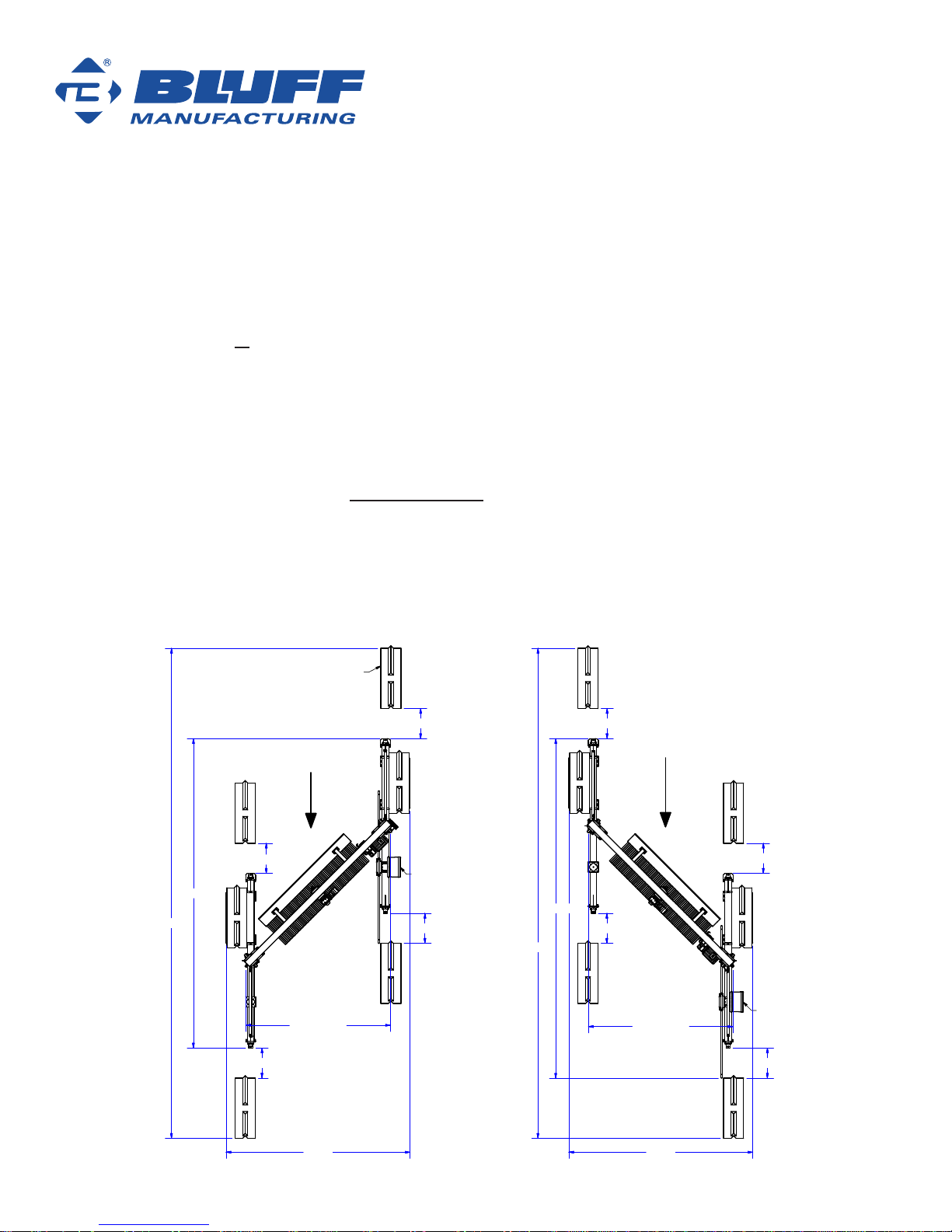
Site Location Requirements - Permanent Model
Please read entire pre-installation manual before proceeding
The rst step in the pre planning process is to determine the best orientation of the unit for your site.
The orientation of the unit determines the material ejection direction. Unit orientations are dened in
the gures below. The standard orientation ejects material away from the operator. The non-standard
orientation, while not ideal, can be used. For permanent units Bluff recommends installing four Bluff
bollards at the entrance and exit to prevent damage from vehicles. We also recommend two additional
bollards to protect the electrical panel.
NOTICE
On a permanent model, orientation cannot be changed without a full reinstall. Please contact
your Bluff Manufacturing dealer or Bluff directly concerning switching unit orientation.
Vehicle Travel Vehicle Travel
Standard
Configuration
Non-Standard
Configuration
185 in
412 in
this drawing is for
Site Location Requirements - Permanent Model
173 in
base to base
173 in
base to base
model for this drawing:
DS-PermanentStandard
model for this drawing:
DS-PermanentNonStandard
445 in
12 in
approx
12 in
36 in
36 in
12 in
Electric
Panel
Electric
Panel
36 in
12 in
approx
12 in
12 in
381 in
421 in
185 in
36 in
Bluff Bollard SRB42
Bluff Bollard
SRB42
Bluff Bollard
SRB42
Bluff Bollard
SRB42
Bluff Bollard
SRB42
Blu
ff Bollard
SRB42
Bluff Bollard SRB42
Bluff Bollard
SRB42
Bluff Bollard
SRB42 Bluff Bollard
SRB42
Bluff Bollard
SRB42
Bluff Bollard SRB42

11
DuraSweeper®
Pad Suggestion for Permanent Installation
The concrete foundation pad for the structure is the most important structural preparation for the Bluff
DuraSweeper®. The suggested pads detailed in the following gures may not be sufcient for all site
locations, so check with your concrete engineer for proper depth, structure, and grade for your site
location.
Concrete pad should be poured by qualied personnel under the direction of properly trained
and qualied supervision. Failure to do so could result in pad failure that could cause serious
injury, death, and catastrophic damage to the equipment.
The pads for each permanently installed column are expected to be level and on-plane to each other.
Some variations may be overcome with shims under the column bases.
Concrete should meet all recommendations of the latest ACI 318 code, particularly with regard to cold-
weather pouring of concrete.
Note: Concrete piers can be used in place of concrete pads. Contact Bluff for additional information.
!DANGER

12
DuraSweeper®
Suggested Concrete Pad Specication - Permanent Model Standard Layout
Concrete pads should be at a minimum 6 inch depth and have a minimum compressive strength of
3,000 lb. Wedge anchors require a minimum embedment depth of 3.375 inches. The minimum pad foot
prints are shown in the Standard Concrete Layout and Non-Standard Concrete Layout. Edge of bollard
base plate should be recessed from all pad edges by at least 6".
Note: Concrete piers can be used in place of concrete pads. Contact Bluff for additional information.
Vehicle Travel
PERMANENT MODEL
Standard Concrete Layout
this drawing is for
Suggested Concrete Pad Specification - Permanent Standard Layout
model for this drawing: DS-PermanentStandardConcrete
25 ft
7 ft
24 ft
3 ft
11 ft
13 ft
12 ft
Bluff Bollard
SRB42
Bluff Bollard
SRB42
Bluff Bollard
SRB42
Bluff Bollard
SRB42
Bluff Bollard
SRB42
Bluff Bollard
SRB42

13
DuraSweeper®
Suggested Concrete Pad Specication - Permanent Model Non-Standard Layout
Concrete pads should be at a minimum 6 inch depth and have a minimum compressive strength of
3,000 lb. Wedge anchors require a minimum embedment depth of 3.375 inches. The minimum pad foot
prints are shown in the Standard Concrete Layout and Non-Standard Concrete Layout. Edge of bollard
base plate should be recessed from all pad edges by at least 6".
Note: Concrete piers can be used in place of concrete pads. Contact Bluff for additional information.
Vehicle Travel
PERMANENT MODEL
Non-Standard Layout
this drawing is for
Suggested Concrete Pad Specification - Permanent Model Non-Standard Layout
model for this drawing: DS-PermanentNonStandardConcrete
25 ft
7 ft
3 ft
24 ft
15 ft
14 ft
Bluff Bollard
SRB42
Bluff Bollard
SRB42
Bluff Bollard
SRB42
Bluff Bollard
SRB42
Bluff Bollard
SRB42
Bluff Bollard
SRB42
Electric
Panel

14
DuraSweeper®
Recommended Safety Barrier Equipment
Bluff Manufacturing recommends you protect your investment in the DuraSweeper®with bollards
or similar safety barrier equipment to prevent possible damage to all the components of the
DuraSweeper®, as well as the electrical panel. Below is a view of our suggestion for that protection. If
you need assistance to obtain the bollards, please contact your Bluff dealer for a quote.
The electrical panel should be secured and cables should be protected from vehicle damage. Power
to the electrical panel should be protected from foot, vehicular, and environmental wear in the best
manner the prevailing conditions on the site allow. While the electrical panel is rated for the cold and
weather, any additional protection provided should increase the working life of the equipment.
Vehicle
Travel
this drawing is for
Recommended Safety Barrier Equipment
model for this drawing: DS-PermanentStandard
Bluff Bollard
SRB42
Bluff Bollard
SRB42
Bluff Bollard
SRB42
Electric
Panel
Bluff Bollard
SRB42
Bluff Bollard
SRB42
Bluff Bollard
SRB42
Power Provisions
Power must be supplied to the unit at the rated voltage and phase required by the model purchased.
Refer to the product specications section of the manual for specic power requirements for your unit.
This power must be provided to the electrical control panel per all regulatory codes that apply to the
location. See electrical schematic in the interior pocket of the electrical enclosure for power connection
points.
!DANGER
Only licensed electricians are allowed to install or work with high voltage connections. Use
proper personal protective equipment as required. Serious injury or death to personnel, or
severe damage to equipment could result from non-compliance.

15
DuraSweeper®
Parts & Assemblies
The following illustrations and diagrams detail the parts and assemblies of the DuraSweeper®by Bluff.
Some pieces are welded together and are considered a single part. Weldments are not considered
wear parts, so damage to any weldment should be reported to Bluff Manufacturing or a Bluff Distributor
immediately. Repairs to weldments will be subject to the judgment of the Bluff engineering team,
and not all weldments can or should be repaired due to safety concerns or feasibility. In such cases,
complete replacement of the weldment will be necessary.
PARTS LIST
TITLEPART NUMBER
QTY
ITEM Assy - Base Module
DS-BS-MOD
11 Horizontal Beam/Hoist AssemblyDS180-003
11.1 Weld - Beam
DS180-00211.1.1 BeamDS180-002-00111.1.1.1 Bracket
DS180-002-002
1
1.1.1.2 End PlateDS180-002-00421.1.1.3 Plate, Cross Brace
DS180-002-00621.1.1.4 Plate, Cable Support
DS180-004-001-01521.1.1.5 Weld - SpoolDS180-003-001
1
1.1.2 Shaft WasherDS180-003-001-00321.1.2.1 Spool Pipe
DS180-003-001-00481.1.2.2Hoist, Drive Shaft
DS180-003-001-00511.1.2.3 Bolt StackupDS180-BS-4
4
1.1.3 Hoist Shaft SpacerDS180-003-002
11.1.4 Bolt Stackup
DS180-BS-1841.1.5 Hoist Package, Key
DS180-003-004
1
1.1.6 Gearbox DriveDS180-003-005
11.1.7 Shaft Collar
SHAFTCOL2002
1.1.8 BearingBRINGMNT4B20011.1.9 Hoist Shaft Spacer
DS180-003-006
1
1.1.10 Base Beam Assy
DS180-00721.2 Brush Carriage Assy
DS180-00411.3 Column Brace
DS180-00821.4 Cable
DS180-009-001
11.5 Assy - Cable, Take-upDS180-BS-7
1
1.6 Column Assy
DS180-01621.7 Bracket
DS180-004-001-02511.8 Assy - Carriage Guide Bracket
DS180-004-00721.9 Bolt StackupDS180-BS-4
4
1.10 Bolt Stackup
DS180-BS-1441.11 Bolt Stackup
DS180-BS-1341.12 Assy - Cable, Static
DS180-BS-8
1
1.13 Prox Switch BracketDS180-030-001
11.14
Rep - Energy Chain Loop
2
11.15
Rep - Wire Rope 2
1
1.16 Prox Switch - Cable SetPROXSWTCHCS15
11.17 Proximity Switch
PROXSWTCH4011.18 Energy Chain, Mounting Bracket, Female
NRGYCHN13MB11.19 Energy Chain, Mounting Bracket, MaleRep - Energy Chain,
4556T66, Male
1
1.20
Energy Chain
NRGYCHN13LNK641.21 Assy - Anchor Package: Permanent
DS180-PERM
1
2Base Anchor Bracket AssyDS180-017
4
2.1 Bolt StackupDS180-BS-1
162.2 Wedge Anchor Kit
F34512WA242.3 Shim
DS-PERM-00182.4 Assy - Control PackageDS-E10
1
3Assy - Drive Package
DS-D1014 Assy - Drive Package
DS-D1515 Assy - Drive Package
DS-D20
1
6Electrical PanelDS-E20
17 Utility vehicle 14.8 m3 color Whiteutility_white
18 Assy - Anchor Package: Portable
DS-PORT19 Jack Assy
DS180-022
4
9.1 Ecology Block PlatformDS180-01329.2 Bolt Stackup
DS180-BS-1369.3 Jack Caster Shoe
DS180-027-00129.4
Ecology Block610 Prox Switch Bracket, LowerDS180-036-0012
11
Illustration for Parts and Assemblies Page
file locations:
model - C:\Users\stevebales\Desktop\DuraSweeperManual\Inventor Model 5\Layout.iam
persentation file - C:\Users\stevebales\Desktop\DuraSweeperManual\Inventor Model 5\DS-MainExplodedView-10HP.ipn
drawing - C:\Users\stevebales\Desktop\DuraSweeperManual\Inventor Model 5\DS-MainExplodedView-10HP.idw
PDF - C:\Users\stevebales\Desktop\DuraSweeperManual\Inventor Model 5\DS-MainExplodedView-10HP.pdf
DS180-003
Horizontal Beam/Hoist Assembly
Ecology Block
*not included
Energy Chain
DS180-022
Jack Assy
4 reqd.
DS180-027-001
Jack Caster Shoe
2 reqd.
Ecology Block
*not included
DS180-013
Ecology Block Platform
2 reqd.
DS180-017
Base Anchor Bracket
4 reqd.
DS-PERM-001
Base Shims
8 reqd.
Notes:
Lifting Cable not shown
Fasteners are not shown. See assembly fasteners list.
Base Package consists of items labeled in BLUE text.
Portable Anchor Package consists of items labeled in RED text.
Permanent Anchor Package consists of items labeled in GREEN text.
DS180-007
Base Beam Assy
2 reqd.
DS180-008
Column Brace
2 reqd.
DS180-016
Column Assy
2 reqd.
DS180-004
Brush Carriage Assy
motor not included
DS-D15 Drive Motor
DS-D20 Drive Motor
DS180-036-001
Prox Switch Bracket
1 upper, 1 lower
(both are identical)
DS180-036-001
Prox Switch Bracket
1 upper, 1 lower
(both are identical)
DS-E10
Electrical Panel
Figure 10

16
DuraSweeper®
NOTE: The Electrical Enclosure is designed and rated for the operation of the DuraSweeper®by Bluff.
It is not intended to supply power to additional add-ons (lights, for example). Nothing additional should
be wired from the electrical enclosure. See product specications for power requirements. The wiring
from the panel to the hoist and brush drive motors is supplied. The customer should comply with all
local electrical codes and regulations. All electrical installation should be performed by a licensed
electrician.
Pre-erection Assembly
The DuraSweeper®by Bluff ships as several pre-assembled components. Before attempting to
install any components, remove packaging and inspect components for any defects or damage.
Closely inspect wire rope and pulleys for defects or damage that might cause premature wear to the
components. Replace wire rope if any damage, kinks, crimps, fraying, loose strands, or broken strands
are found.
Installation Tips
• Installation site should be clear of debris and clutter - clear snow to surface.
• Make sure to plan the area so that there is plenty of room to maneuver the trucks through the unit
and plenty of space for the ejected snow.
Prevailing wind direction during snow season should be considered to maximize the distance
and direction the snow will be ejected.
• Carefully read and understand all sections of this manual before attempting the installation. The
pages listed below are also in the Pre-Installation Guide For Bluff DuraSweeper®:
- Ejected Material and Clear Lane
- Site Location Requirements – Portable Model
- Site Location Requirements – Permanent Model
- Pad Suggestion for Permanent Installation
- Suggested Concrete Pad Specication – Permanent Model Standard Layout
- Suggested Concrete Pad Specication – Permanent Model Non-standard Layout
- Recommended Safety Barrier Equipment
• These installation instructions describe a typical installation for a portable or a permanently installed
unit. There may be installations that require special requirements not covered in this manual. Contact
Bluff Manufacturing in those cases.
• When assemblies involve an array of bolts, it is always good practice to install and snug all the bolts
before fully tightening any of them. Tightening each bolt as it is installed will result in difculties
during the installation.
Installation On-Site

17
DuraSweeper®
Recommended Tools
The following are recommended for this installation:
• Boom Lift with a man basket with minimum 30’ lifting height and a minimum 8,000 lb. lifting capacity.
• Two lifting slings are recommended when lifting the main structure. Slings need to have a minimum
capacity of 2000 lbs. each (when used in a choker conguration).
• Heavy duty saw horses or equivalent to support the structure during the initial structure assembly.
• A spud wrench is strongly recommended to align bolt holes, etc.
• Assorted wrenches, ratchets, etc.
This manual suits for next models
4
Table of contents
Other Bluff Industrial Equipment manuals


