bluMartin freeair plus User manual

Operating Manual
[ G ] General
[ O ] Operation
[ I ] Installation
[ S ] Service
Quick Start Guide
Quick Start Guide
Comfort-Level
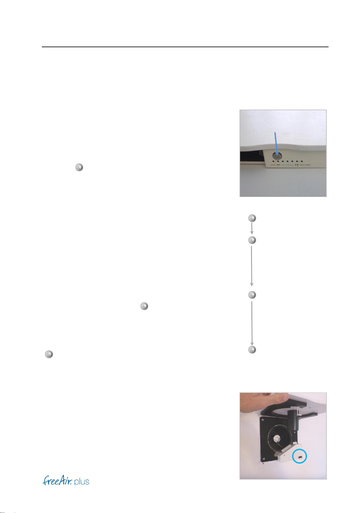
Press the - Button repeatedly to change the Comfort Level.
More blue LEDs indicate a more active operation (minimum
ventilation, humidity, CO2, cooling ... etc.). However, a change
in Comfort Level does not have to lead to the immediate increase
in fan speed.
Blinking blue LEDs indicate Service Operation.
Turbo / Reset
If you want to ventilate your rooms on the highest fan level for 30
minutes (Turbo mode), push the - Button until you hear 4 short
beeps.
The unit performs a software reset when you press the
- Button for 15 more seconds until the LEDs turn off. This is
e.g. required for software updates.
Standby
The unit switches on as soon as it is connected to the power
supply. When the unit is not needed, you can activate the
standby mode via the DIP-Switch (behind the front plate).
Beep
→Comfort-Level
Beep
Beep
Beep
Beep
→Turbo
15 more seconds
→Reset
General
1
[ G ]
Dear customer
We thank you for choosing our freeAir ventilation system. Please read and follow this manual
thoroughly.
After successful installation please select the desired Comfort Level. The sensor technology
and the intelligent control of your freeAir will do the rest.
Enjoy the heightened sense of wellbeing offered by constant good air quality.
Your bluMartin-Team
General
2
[ G ]
General
Safety –General
This manual is only valid for the intelligent active transfer unit freeAir plus.
This manual is delivered as part of the device. Please keep this manual readily available.
Please make sure that all persons operating the device are familiar with this manual. Please
observe all instructions given in this manual.
Installation, commissioning and servicing must only be performed by sufficiently qualified
personnel.
Failure to comply with this manual voids the warranty.
Please also observe our general terms and conditions at www.bluMartin.de/cos.
Safety –Icons
DANGER
This sign indicates danger by potentially deadly electrical shock.
DANGER
This sign indicates that instructions must be followed precisely in order to prevent injuries of
persons or material damage.
Warning
To avoid any property damage please pay special attention to this sign.
General
3
[ G ]
Notes
This sign emphasizes important information.
Safety indications
DANGER
•The device is operated electrically. Some parts of the device carry line voltage even several
minutes after unplugging the device.
•Never open the device while appliance is plugged in.
•Electrical installation as well as electrical service work must only be performed by qualified
personnel.
•Electrical installation has to be in accordance with the appropriate national association
or the safety regulations of your country.
•All instructions and notes with respect to maintenance (see Service paragraph) are to be
implicitly followed.
•The device may only be operated in perfect technical condition and unaltered condition.
In case of error or damages that constitute a safety issue turn the device off.
Prevent the device from being turned back on by unauthorized persons, and have the
device immediately repaired by a qualified technician.
•Only use original bluMartin GmbH repair and service parts.
General
4
[ G ]
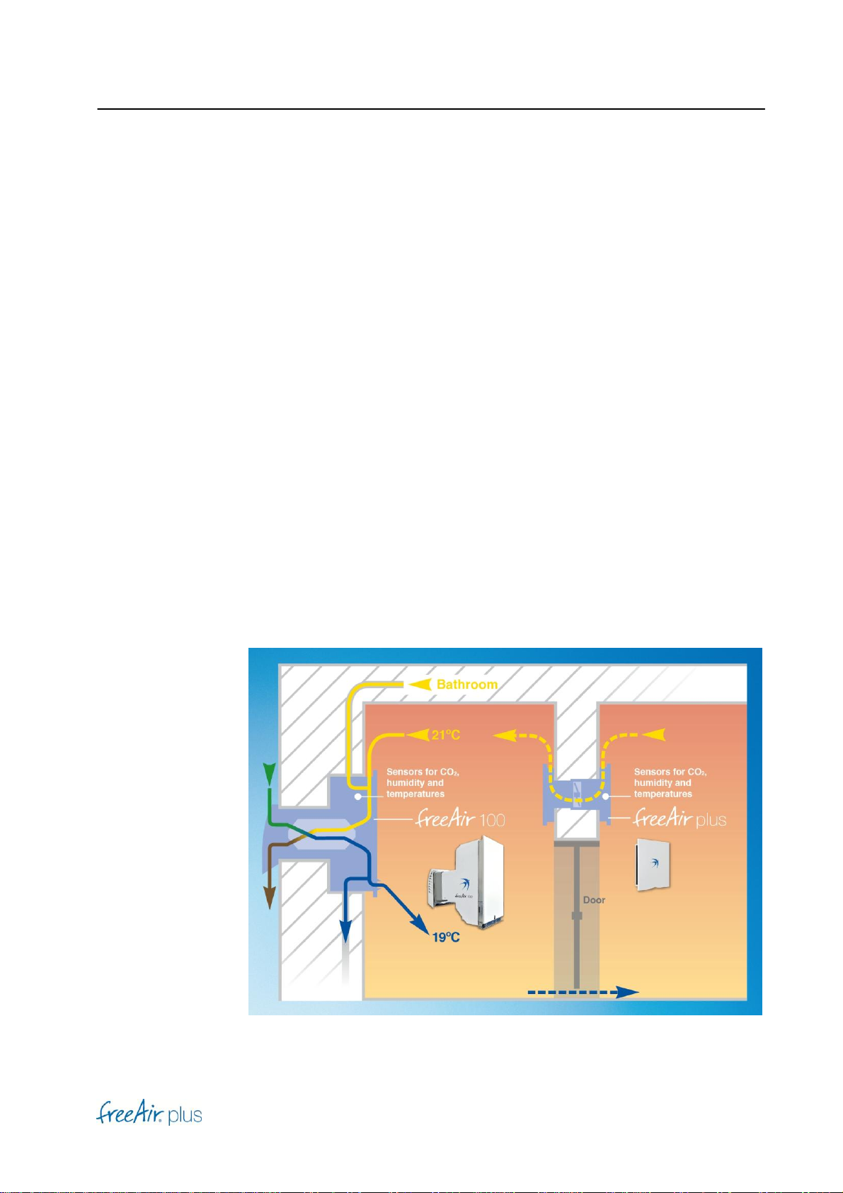
Intended use
The freeAir plus is an intelligent active transfer unit that ventilates rooms in apartments or
houses. The device is installed in an inside wall.
Stale air is drawn from the Preferred Room that is connected via the freeAir plus. Fresh air from
the Outdoor Air Room (e.g. the corridor) streams in the Preferred Room (e.g. the sleeping room)
through the gap under the door or through another appropriate passive vent. If the measured air
quality in the Outdoor Air Room is lower than in the Preferred Room, the ventilation is reduced.
Inappropriate use
The device is exclusively to be used for ventilation purposes.
DANGER
Only air not containing flammable, explosive or corrosive components or air not containing any
other dangerous or hazardous components may be used for ventilating purposes.
Disposal
Dispose the freeAir plus in accordance with your local rules, regulations or guide lines.
Please pay special attention to correctly sorted separation of metal, plastics and electronics.
General
5
[ G ]
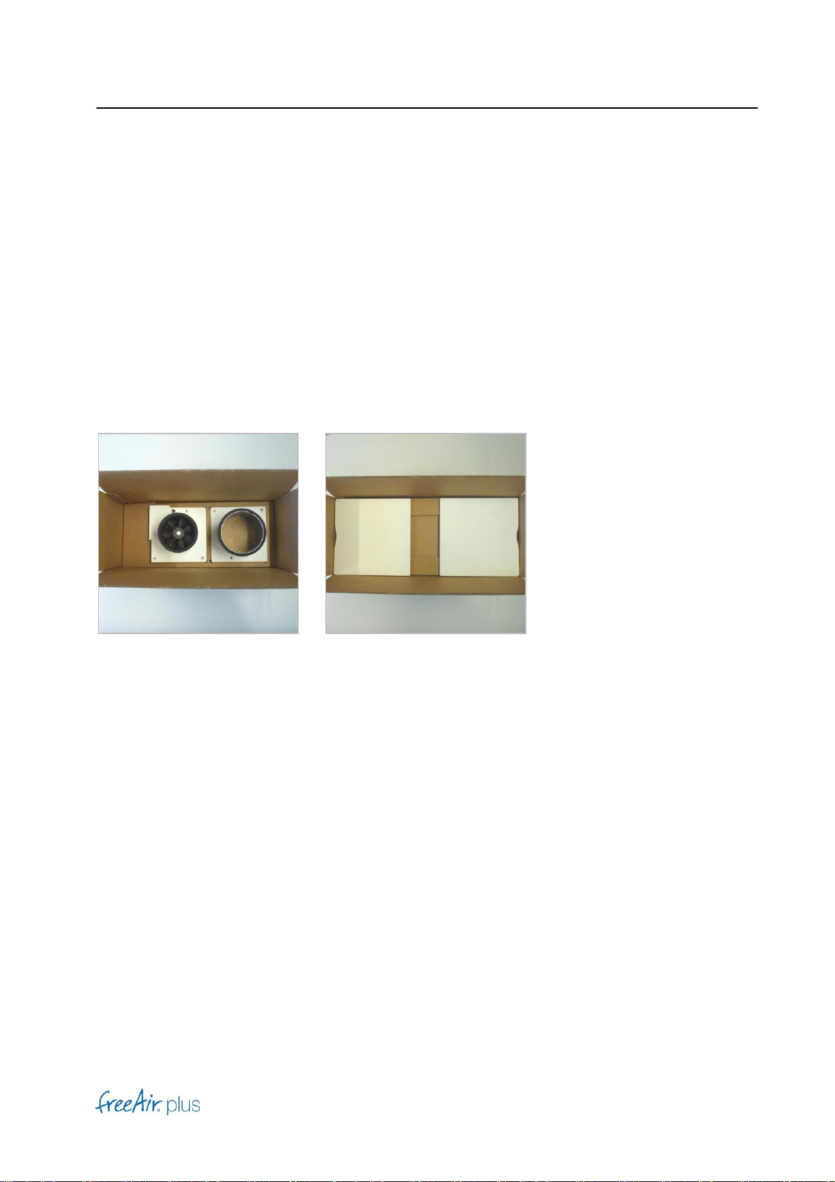
Transport and storage
Components of the freeAir plus may only be transported in the intended packaging. Packaging
must be protected from moisture.
Included in shipping
freeAir plus front plates

General
6
[ G ]
Technical Data
Dimensions front plate 25 x 25 cm
Wall thickness 10 to 22 cm including render/ plaster
(< 12 cm with spacers supplied)
Wall breakthrough 16 cm round
Airflow rate 10 to 70 m3/h
Power supply 85 to 265 V AC
Mains fuse 0,315 A slow (on motherboard)
Line frequency 45 to 65 Hz
Total Power Consumption Standby → 0,5 W; 30 m3/h →0,9 W;
50 m3/h →1,4 W; 70 m3/h → 2,5 W
Weight 3 kg
Sound pressure level 30 m3/h →13 dB (A) (at 1 m distance);
50 m3/h →25 dB (A);
70 m3/h →37 dB (A);
Sound insulation factor 33 dB (EN ISO 10140-2; Dn, e, w)
Control Intelligent 5 level Comfort Control
Airflow control Automatic; virtually infinitely variable
CO2control (VOC) Automatic
Dehumidification Automatic
Summer cooling Automatic
Temperature range 0 to +40°C
Colour Front plate primer painted (ready to paint, lacquer or design)
Operation
7
[ O ]
Operation
Warning
Follow all safety and applications for the freeAir plus under chapter [G] General.
Indicators and Control Elements
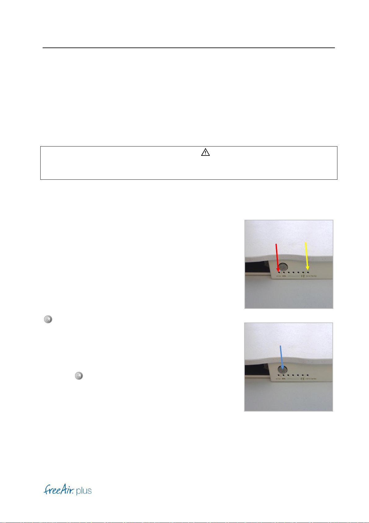
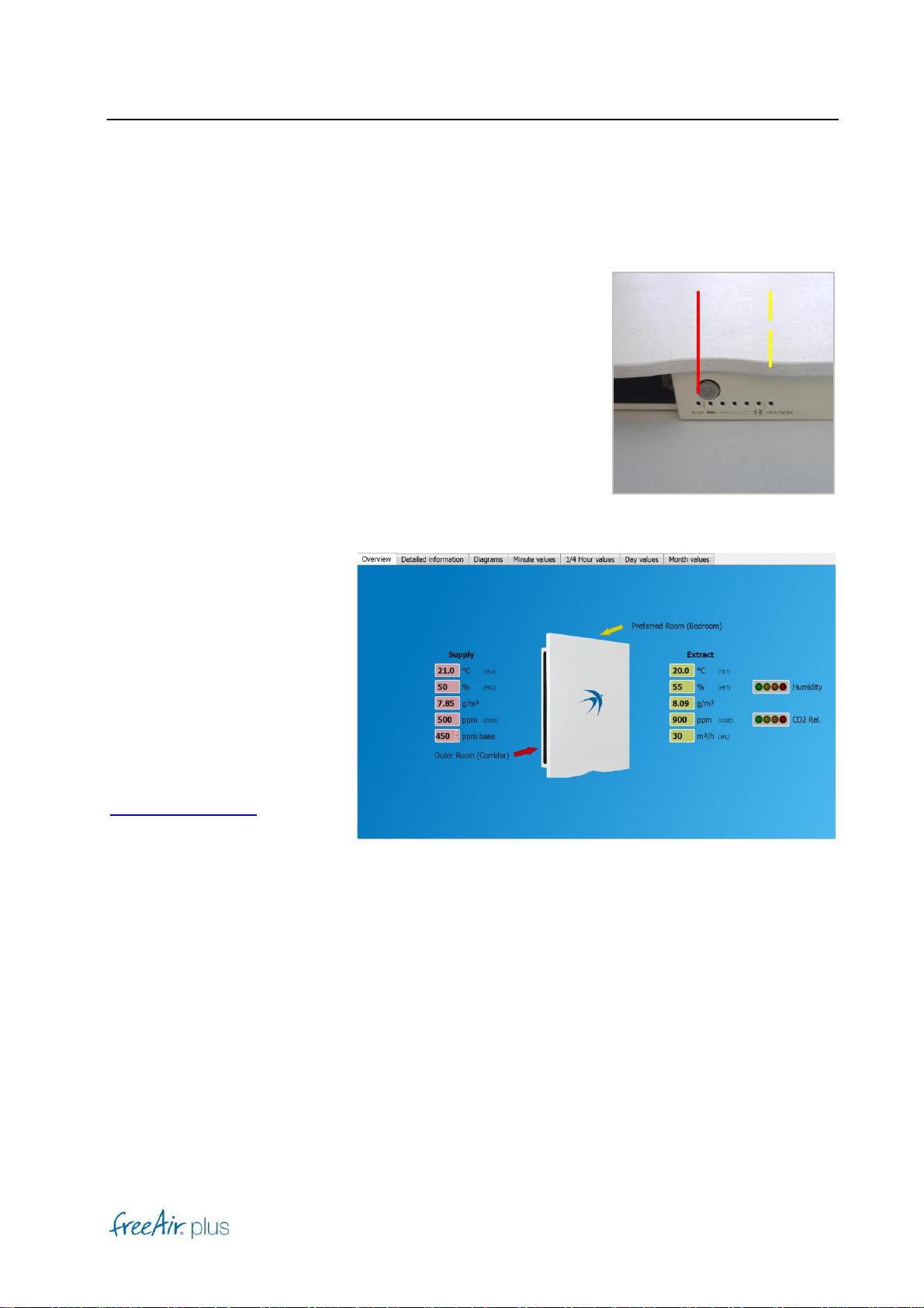
Start-up
After connecting the freeAir plus to electrical power, or after a
reset, the red and yellow LED will be on for a few seconds
(system is searching for a USB connection to a PC).
Afterward, the freeAir plus is ready for operation.
-Button
Operating the freeAir plus is so simple, this button is the only
control element you need.
Comfort selection as well as starting or stopping turbo operation
is done via this button (see below).
Press the -Button multiple times to select your preferred
comfort level.
The freeAir operation activity increases ventilation, CO2 ,
humidity and cooling, the more blue LEDs are lit. You may or
may not hear a change in fan speed.
Operation
8
[ O ]
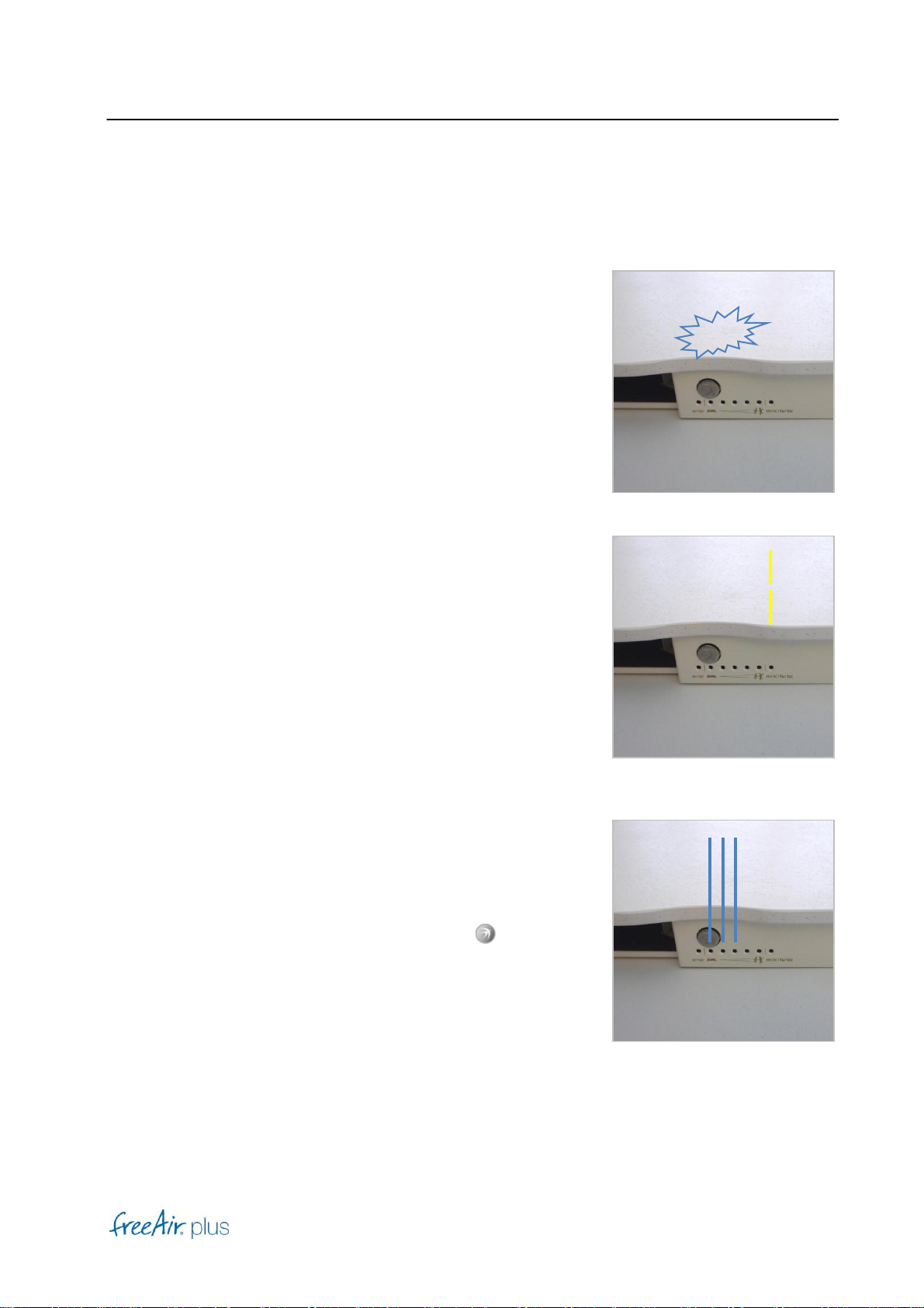
Audible Signals
A continuous beep sound indicates elevated temperatures (see
chapter [S] Service).
Yellow LED
During turbo operation, the yellow LED will blink.
Yellow LED stays on, indicates reduced ventilation, in cases
where the air quality in the Outdoor Air Room (e.g corridor) is
worse compared to the air quality in the Preferred Room (e.g.
Bedroom).
Blue LEDs
Number of blue lit LEDs indicates selected comfort level.
Note
Blue LEDs turn off after 3 minutes. Pressing the -Button, will
turn them back on.
Piep
Operation
9
[ O ]
Red LED
Red LED stays on and blinking yellow LED indicates a control
error (see chapter [S] Service)
USB-Port
The USB port on the right side
of the freeAir, is used to
connect to your free copy of
freeAir-Connect software for
updates.
Note
For software updates, visit
WWW.bluMartin.de under
service and Downloads.
Operation
10
[ O ]
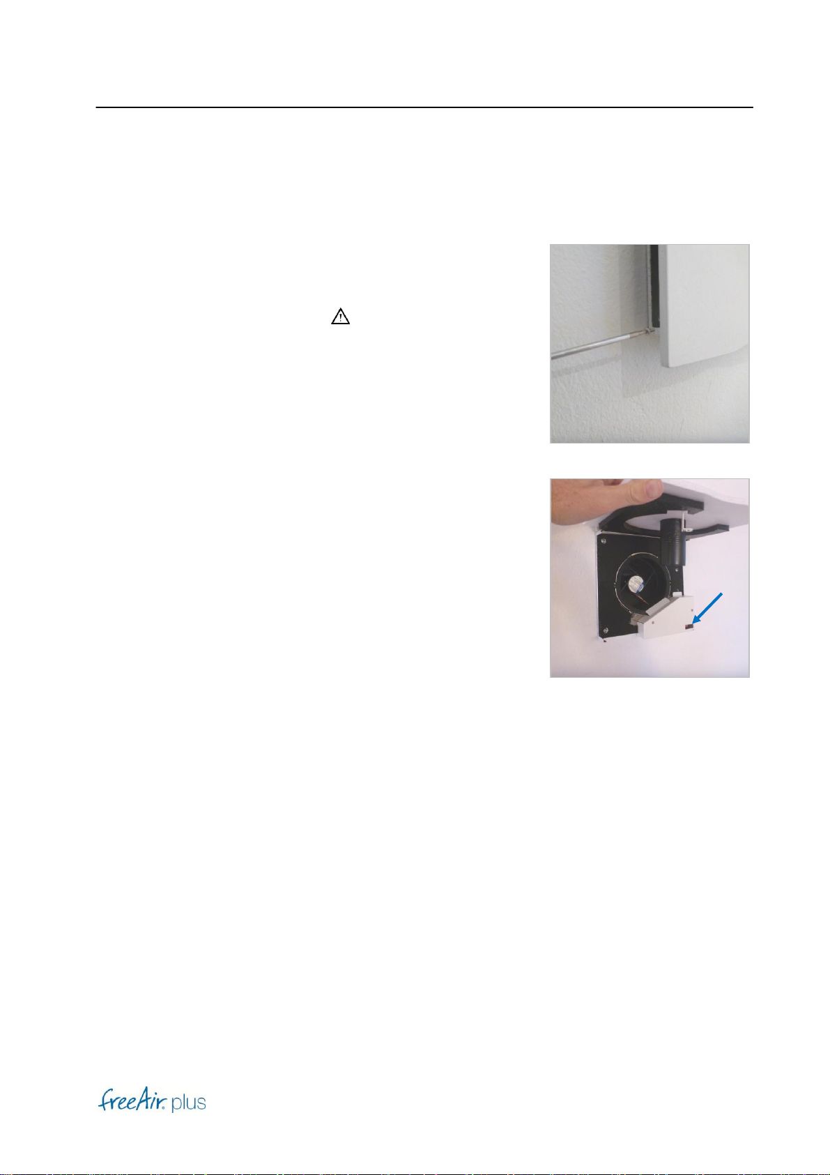
Fan
After removal of the front cover, the fan is freely accessible.
Warning
•Do not reach into the spinning fan! Spinning blades will
lead to injuries.
•Do not stick any objects into the fan.
•Always secure the front cover with safety screw.
Note
For cleaning operations, activate the standby operation at the
DIP switch.
Operation
11
[ O ]
Comfort-Operation
The freeAir plus will operate in Comfort-Mode after it is turned on.
The device will automatically operate as expected: The connected
Preferred Room will be supplied with as much fresh air as possible
(based on intended use of the device, correct installation and available
fresh air in the Outdoor Air Room, fresh air is drawn from).
The freeAir plus will take minimal ventilation, VOC content, relative and
absolute humidity, temperature and potential cooling into account.
Use the –Button to select Comfort-Level 1 (one blue LED is lit), if you
are sensitive to noise in the bedroom. Comfort-Level 3 is considered
standard operation.
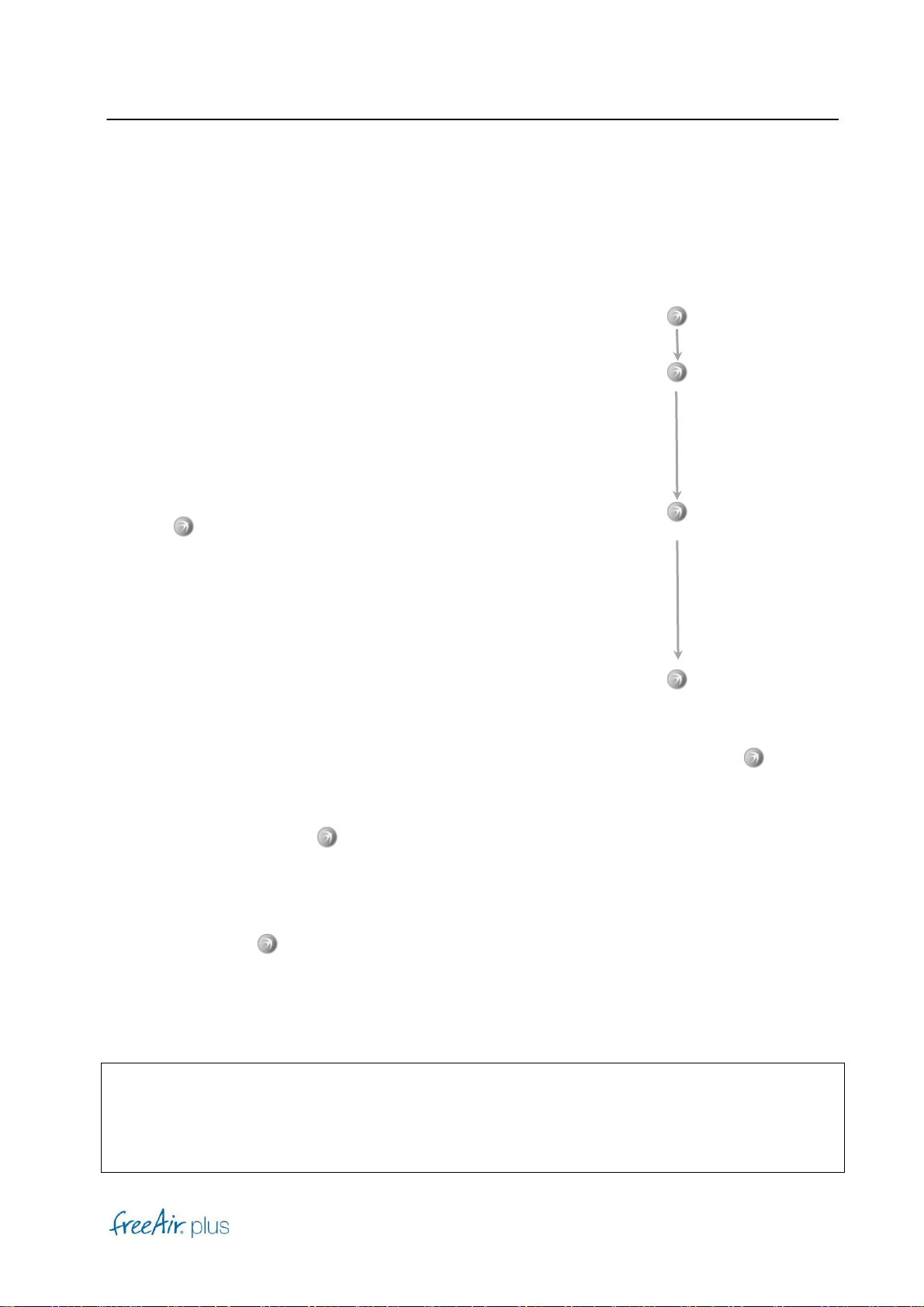
Turbo-Operation
If you wish to ventilate for 30 minutes at the highest power level, press and hold the –Button
until you hear 4 short beeps.
Normal Comfort-Operation will resume afterward. Maximum power ventilation can be
interrupted by pressing the –Button.
Reset
Press and hold the –Button for 20 seconds until all LDS are off.
The freeAir plus will respond with a software reset, (also required for a software update), and
return to normal Comfort-Level operation.
Note
The freeAir plus includes a VOC-sensor that measures the concentration of volatile organic
compounds, thereby comparing air quality in both connected spaces. To simplify, VOC data is
converted to CO2 values.
Beep
→Comfort-Level
Beep
Beep
Beep
Beep
→Turbo
15 Seconds
→Reset

Installation
12
[ I ]
Installation
DANGER
Please regard the safety advices in part General [G]. Observe all notes with respect to safety
and use of the freeAir plus.
Notes
•Your freeAir plus draws stale air from the room that is connected via the freeAir plus. To
ensure an unhindered air inflow from the Outdoor Air Room (e.g. carridor) to the
Preferred Room, please take care that there is an appropriate opening with a cross section
of at least 80 cm2(e.g. a gap under the door of 1 cm).
•The side of the device with the operating element is mounted in the Outer Room
•The Outdoor Air Room is continuously supplied with fresh air by a freeAir 100 ventilation
unit.
Installation site
DANGER
•The freeAir plus must not be installed in immediate vicinity of flammable material or
harmful chemicals.
•During planning consider all relevant local building, safety and fire codes. Especially in
situations where indoor air is used for combustion (wood stove, fire place...etc.).
Notes
•During operation the room temperature must be between 0°C and 40°C.
•Condensation of water must not occur in the freeAir plus unit.

Installation
13
[ I ]
Drawings

Installation
14
[ I ]
Brickwork
1. Determine the mounting position and sketch a round
cut-out with a diameter of 16 cm on the wall.
Note
Technically speaking the higher up on the wall the device
is installed the better the performance. For optical reasons
the device can also be placed lower.
2. Drill the hole into the wall.
3. An authorized electrician installs the connection line
3 x 1,5 mm2in the Outdoor Air Room.
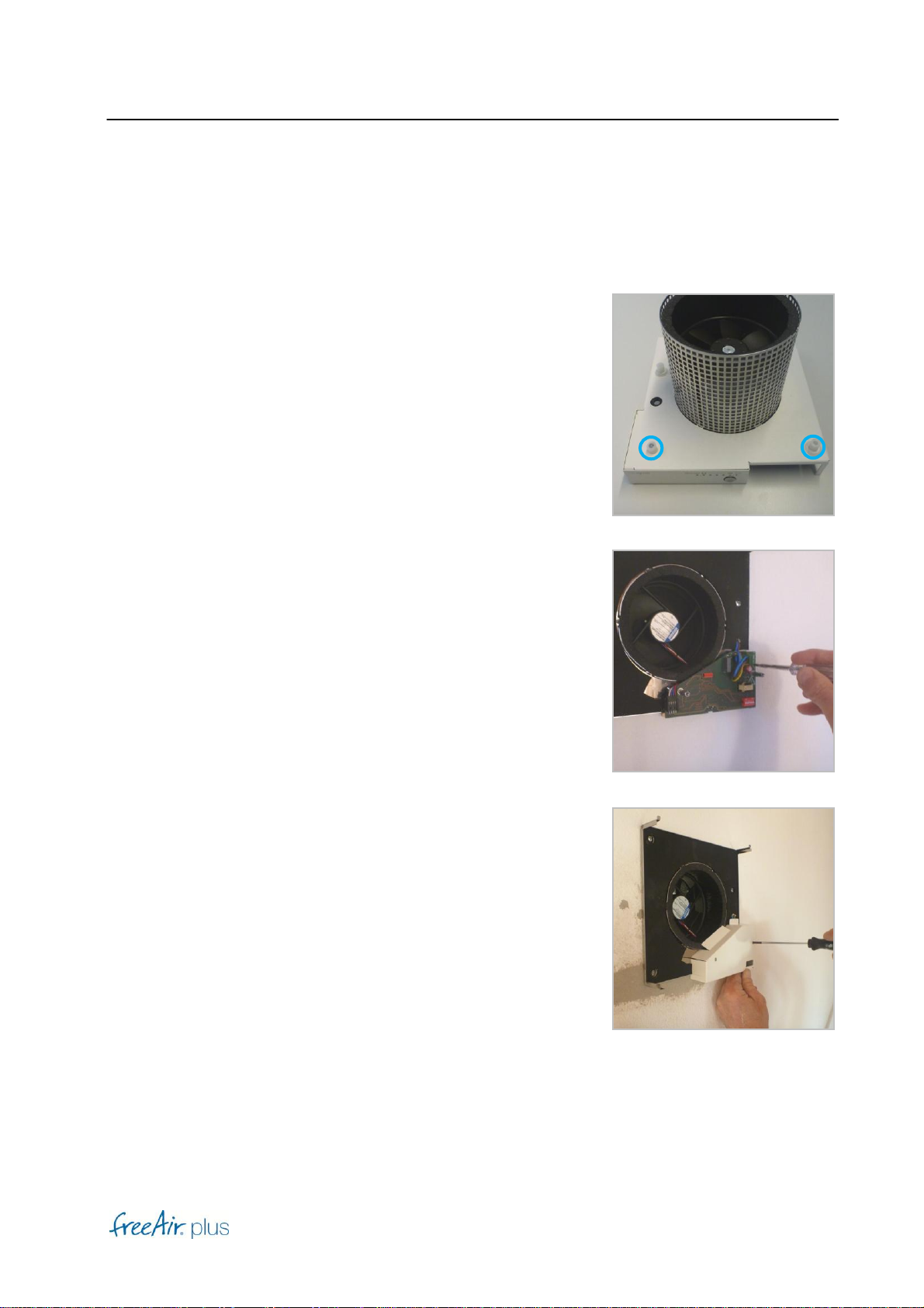
Installation
15
[ I ]
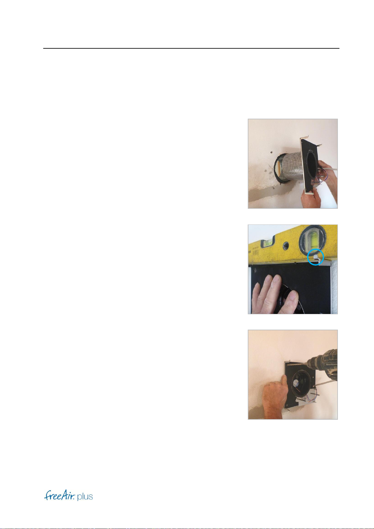
4. First insert the side of the device without the operating
element in the Preferred Room (e.g. sleeping room).
The side of the device with the operating element is
inserted in the Outdoor Air Room (e.g. corridor).
Note
The Outdoor Air Room is continuously supplied with
fresh air by a freeAir 100 ventilation unit.
5. Mark 3 drillholes for an exact horizontal position.
Note
The both hooks for the front plate must face upwards.
6. Set the drillholes precisely in both frames.
Installation
16
[ I ]
7. If your wall is thinner than 12 cm please mount the
both halves of the device with the supplied spacers.
8. An authorized electrician connects the freeAir plus
with a connecting line 3 x 1,5 mm² to the power
supply. If possible please connect all ventilation
units of a housing unit to an own shared fuse.
9. Activate the power supply at the fuse box only after
closing of the casing.

Installation
17
[ I ]
DIP switch
Standby / Service
If you want to deactivate the device please select
position ON here.
Summer cooling (°C)
A special feature of your freeAir plus is the automatic summer cooling. When the air in the Outer
Air Room is cooler than in the Preferred Room during the warmer seasons (mostly at night), the
freeAir plus increases the airflow automatically.
Please select the desired temperature for the connected room.
Room Area (m2)
Please select the ventilated floor space. Consider all connected rooms.
This indication is the basis for calculating the minimum ventilation.
Room Area [m2]
Installation
18
[ I ]
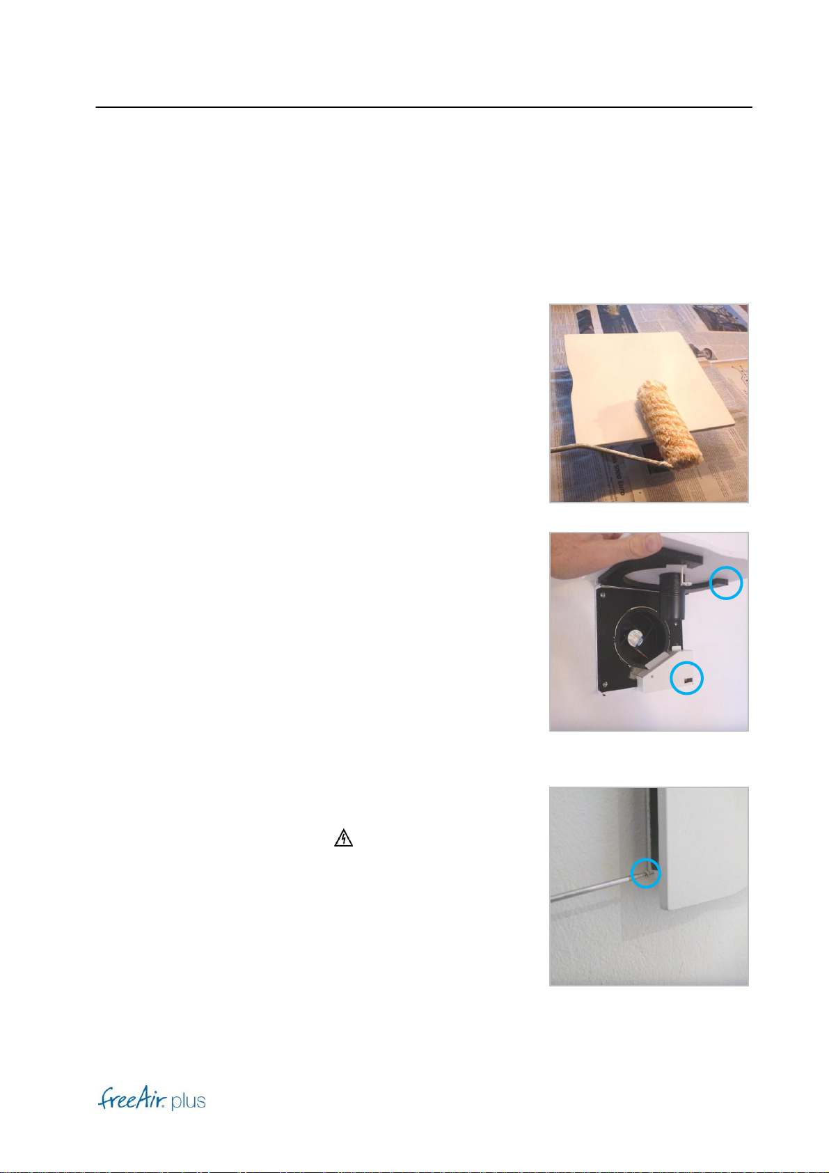
Front plate installation
1. Paint the front plates in a colour of your choice
(wall paint or lacquer).
2. Set the fitting front plate (please note the foam cutting) on
the top of the device and pivot the plate downward until
the plate is held by the magnet.
Note
Before please set the DIP switch correctly (see above in
this chapter).
3. Mount the front plate safety screw.
DANGER
A missing safety screw on the front plate may cause
injuries by the fan.
Table of contents


