manuals.online logo
Brands
  1. Home
  2. •
  3. Brands
  4. •
  5. SunSun
  6. •
  7. Water Filtration System
  8. •
  9. SunSun CPF Series User manual

SunSun CPF Series User manual

This manual suits for next models

21

Other SunSun Water Filtration System manuals

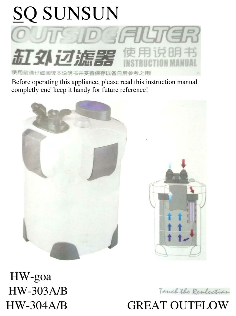
SunSun HW-goa User manual

SunSun

SunSun HW-goa User manual

SunSun CPF-50000 User manual

SunSun

SunSun CPF-50000 User manual

SunSun CPA-2500 User manual

SunSun

SunSun CPA-2500 User manual

SunSun CBG-500 User manual

SunSun

SunSun CBG-500 User manual

SunSun CUV-1 Series User manual

SunSun

SunSun CUV-1 Series User manual

SunSun CBG-500 User manual

SunSun

SunSun CBG-500 User manual

SunSun HW-302 User manual

SunSun

SunSun HW-302 User manual

SunSun CUF-2500 User manual

SunSun

SunSun CUF-2500 User manual

SunSun CBF-200T User manual

SunSun

SunSun CBF-200T User manual

SunSun CUF Series User manual

SunSun

SunSun CUF Series User manual

SunSun CBF-350 User manual

SunSun

SunSun CBF-350 User manual

SunSun HW-702A User manual

SunSun

SunSun HW-702A User manual

SunSun HBL-801 User manual

SunSun

SunSun HBL-801 User manual

Popular Water Filtration System manuals by other brands

Atlantic Ultraviolet Mighty Pure MP16A owner's manual

Atlantic Ultraviolet

Atlantic Ultraviolet Mighty Pure MP16A owner's manual

Hayward XStream Filtration Series owner's manual

Hayward

Hayward XStream Filtration Series owner's manual

Contech DownSpout StormFilter Operation and maintenance

Contech

Contech DownSpout StormFilter Operation and maintenance

Teka Airfilter MINI operating instructions

Teka

Teka Airfilter MINI operating instructions

Wisy LineAir 100 Installation and operating instructions

Wisy

Wisy LineAir 100 Installation and operating instructions

Schaffner Ecosine FN3446 Series User and installation manual

Schaffner

Schaffner Ecosine FN3446 Series User and installation manual

Pentair FLECK 4600 SXT Installer manual

Pentair

Pentair FLECK 4600 SXT Installer manual

H2O International H20-500 product manual

H2O International

H2O International H20-500 product manual

Renkforce 2306241 operating instructions

Renkforce

Renkforce 2306241 operating instructions

Neo-Pure TL3-A502 manual

Neo-Pure

Neo-Pure TL3-A502 manual

STA-RITE VERTICAL GRID DE FILTERS S7D75 owner's manual

STA-RITE

STA-RITE VERTICAL GRID DE FILTERS S7D75 owner's manual

Applied Membranes W-G844EM Operation and maintenance manual

Applied Membranes

Applied Membranes W-G844EM Operation and maintenance manual

BEGA 116 Instructions for use

BEGA

BEGA 116 Instructions for use

WATA Standard operating instructions

WATA

WATA Standard operating instructions

Price FFU series Installation and service manual

Price

Price FFU series Installation and service manual

Gaggenau BRITA INTENZA 467873 manual

Gaggenau

Gaggenau BRITA INTENZA 467873 manual

Brita SAFF-100 user guide

Brita

Brita SAFF-100 user guide

HEISSNER FPU24000-00 Instructions for use

HEISSNER

HEISSNER FPU24000-00 Instructions for use

manuals.online logo
manuals.online logoBrands
  • About & Mission
  • Contact us
  • Privacy Policy
  • Terms and Conditions

Copyright 2025 Manuals.Online. All Rights Reserved.

Operation Manual
Pressure Filter CPF Series
50105, 50123, 50977–50980, 50121, 51042–51044
Illustrations similar, may vary depending on model
Read and follow the operating instructions and safety information before using for the first time.
Technical changes reserved!
Due to further developments, illustrations, functioning steps and technical data can differ insignificantly.
Updating the documentation
If you have suggestions for improvement or have found any irregularities, please contact us.
© by WilTec Wildanger Technik GmbH Item 50105, 50123, 50977–50980, 50121, 51042–51044 Page 2
http://www.WilTec.de
http://www.aoyue.eu 09 2021-1
http://www.teichtip.de
The information contained in this document may alter at any time without previous notice. It is prohibited
to copy or spread any parts of this document in any way without prior written allowance. All rights re-
served.
The WilTec Wildanger Technik GmbH cannot be held accountable for any possible mistakes in this
operating manual, nor in the diagrams and figures shown.
Even though, the WilTec Wildanger Technik GmbH has undergone biggest possible efforts to ensure
that the operating manual is complete, faultless and up to date, mistakes cannot be entirely avoided.
If you should find a mistake or wish to make a suggestion for improvement, we look forward to hearing
from you.
Send an e-mail to:
[email protected]
or use our contact form:
https://www.wiltec.de/contacts/
The most recent version of this manual in various languages can be found in our online shop via:
https://www.wiltec.de/docsearch
Our postal address is:
WilTec Wildanger Technik GmbH
Königsbenden 12
52249 Eschweiler
Germany
Do you wish to pick goods up? Our pick-up address is:
WilTec Wildanger Technik GmbH
Königsbenden 28
52249 Eschweiler
Germany
To shorten the waiting time and allow for a rapid on-site transaction, we ask you to call us previously or
placing your order via the webshop.
E-mail: service@wiltec.info
Tel:+49 2403 55592-0
Fax: +49 2403 55592-15
To return orders for exchange, repair or for other purposes, please use the following address. Attention!
To allow for a smooth execution of your complaint or return, it is important to contact our customer
service team before returning the goods.
Returns Department
WilTec Wildanger Technik GmbH
Königsbenden 28
52249 Eschweiler
E-mail: [email protected]o
Tel:+49 2403 55592-0
Fax: +49 2403 55592-15
© by WilTec Wildanger Technik GmbH Item 50105, 50123, 50977–50980, 50121, 51042–51044 Page 3
http://www.WilTec.de
http://www.aoyue.eu 09 2021-1
http://www.teichtip.de
Introduction
Thank you for purchasing this quality product. To minimize the risk of injury we urge that our clients
take some basic safety precautions when using this device. Please read the operation instruc-
tions carefully and make sure you have understood its content.
Keep these operation instructions safe.
Safety guideline
BEWARE:
The use of this device is allowed on standing water bodies, garden pond water or swimming ponds and
their surrounding areas is only allowed with a fault current protection-switch with a triggering nominal
current up to 30 mA (according to VDE 0100 article 702 and 738).
The device is not suitable for use in swimming pools, paddling pools and other water bodies where there
are people or animals during operation. The operation of the device during the presence of people and
animals in the danger zone is not allowed. Ask your electrician.
The device is not intended for use by persons (including children) with impaired or limited physical,
sensory and mental abilities or lack of experience and/or real knowledge, unless they are supervised by
a person responsible for their safety or follow the instructions made by this person on how to use the
device correctly.
Children should be supervised to make sure that they do not play with the device.
ATTENTION:
•Run a visual inspection of the device before every use. Do not use the device if the safety
appliances are damaged or worn out. Never override safety regulations.
•Use the device exclusively according to the intended purpose stated in the instructions for use.
•You are responsible for the safety of the working environment.
•If the cable or the plug is damaged due to external influences, the cable must not be repaired!
It has to be replaced with a new one. This work can be carried out only by an electrician.
•The voltage indicated on the type plate of the device of 230 V AC has to correspond to the
existent mains voltage.
•Never lift, carry or fixate the device by using the power cable.
•Make sure that the electrical plug connection is placed in a flood-proof area and is protected
from moisture.
•Before working on the pond filter disconnect the appliance by taking the plug out of the socket.
•Avoid exposing the appliance to a direct water jet or rain.
•The user is responsible for the compliance with local safety and installing regulations. Ask an
electrician.
•Consequential damage arising from flooded rooms caused by dysfunctions of the appliance
must be avoided by means of the appropriate measures (e.g., installing an alarm system, re-
serve pump).
•In case of malfunction, the repair work can be carried out only by a qualified electrician.
•The appliance must not run dry or with an intake port completely closed. The manufacturer’s
warranty is no longer valid if the damage is caused by dry running.
•The appliance must not be used for swimming pools.
•The appliance must not be used for drinking water circuits.
•The device has to be installed out of water.
•The distance from the device to the pond has to be at least 2 m.
•You have to make sure that the filter cannot fall into the water.
•You have to make sure that the filter is not exposed directly to sunlight.
•The pond pressure filter has to be horizontally fixed with screws on a suitable mounting place.
•The universal hose stepped tails can be shortened according to the hose diameter if necessary.
© by WilTec Wildanger Technik GmbH Item 50105, 50123, 50977–50980, 50121, 51042–51044 Page 4
http://www.WilTec.de
http://www.aoyue.eu 09 2021-1
http://www.teichtip.de
•Attach hoses and hose clamps.
•Although the ultraviolet radiation is the lowest of the ionizing radiation, it can be dangerous for
people and other organisms as well. UV radiation with longer wavelengths can destroy the
chemical bonds of the organic molecules, too. Therefore, a responsible approach is necessary
when dealing with technical UV sources.
•Only operate the tubes inside a housing that is closed and not cracked.
WARNING:
Read carefully all the safety guidelines and the instructions.
Non-compliance with the safety rules and regulations can lead to an electric shock, fire and/or serious
injury. Keep the instructions and the safety guidelines in a safe place in case you need them in the
future.
Stability
•The temperature of the conveyed liquid should not exceed +35 ℃in permanent operation.
•The conveyance of flammable, gassing or explosive fluids is forbidden. This pump cannot be
used for other fluids particularly not for motor fuels, cleaning agents or other chemical products.
Electrical connection
The electrical connection takes place via an electric safety socket 230 V ~ 50 Hz. Fuse protection at
least 10 A.
Warning:
•The UVC filter should be placed in such a way so that the water cannot reach it. The distance
between the pond edge and the filter should reach at least 2 m. The UV lamp cannot be oper-
ated under water.
•The power supply of the UVC filters must not be turned on before the water circulation has been
carried out.
•Please position the UVC filter on a safe and stable place because the pond filter light tube (the
tube that conveys the light) is made of quartz glass that can burn easily.
•Do not turn the power on before all the component parts of the device are installed.
•If the quartz glass tube or the upper part of the UVC filter is damaged, the pond pressure filter
cannot be used.
•The UVC filter cannot be used either if there are people in the pond water.
•Make sure that the used voltage and the frequency correspond to those indicated on the filter
label.
•When the device is installed, you have to pay attention to the domestic installation rules.
•Please do not pull on the connecting cord. Keep it away from heat, grease and sharp objects.
•Make sure the upper part of the filter is exposed to pressure lower than 0,3 bar.
•In frosty weather please remove the UV filter.
•When you install the UV filter, do not expose it to direct sunlight.
•Dirt influences the efficiency of the quartz glass tube; therefore, it needs to be regularly cleaned.
•To secure the proper functioning of the device, the UV-quartz tube should be replaced after
8000 operating hours.
•If the upper part is blocked by sand, the quartz tube can be destroyed. Please place the filter
sponge in the inlet of the water pump.
•UV light is harmful for theeyes and skin. Do not look directly into the UV light, and do not expose
your skin to it.
•If you install the device or repair it, switch off the power supply of the lamp and the pump.
•The device must be installed on a horizontal flat surface with the feet downwards. For safety
reasons, it not allowed to install the device otherwise.
© by WilTec Wildanger Technik GmbH Item 50105, 50123, 50977–50980, 50121, 51042–51044 Page 5
http://www.WilTec.de
http://www.aoyue.eu 09 2021-1
http://www.teichtip.de
Application area/functioning
This UVC device ensures clear water for healthy fish. The water is pumped by a pump through the UVC
device. There it flows past the UV lamp and is exposed to UVC radiation. Thus, the bacteria, germs and
floating algae in the water are destroyed, and the water is clarified.
To achieve an optimal result the device should be operated 24 hours in the frost-free seasons.
Commissioning
Switch on the pump and wait until the device is filled with water. Check if all connections are well sealed.
By plugging in the power cable, the device is put into operation.
Technical data
Model
Item
number
Power
(W)
Tension
(V)/fre-
quency (㎐)
Suitable for … up to
(ℓ)
Recom-
mended
max. flow
rate (ℓ⁄h)
Input/output
(㎜)
Fish
ponds
Decora-
tive
ponds
CPF-180
50123
11
230 / 50
3000
6000
9000
19/25/32/40
CPF-250
50105
5000
10000
10000
CPF-280
51042
4000
8000
9000
19/25/32/38
CPF-380
51043
6000
12000
10000
CPF-500
51044
18
10000
30000
CPF-2500
50978
11
3000
6000
6000
19/25/33
CPF-5000
50976
4000
8000
9000
19/25/32/40
CPF-10000
50977
6000
12000
10000
CPF-15000
50121
18
10000
30000
CPF-20000
50979
36
20000
40000
12000
32/38
CPF-30000
50980
55
30000
60000
32/38
Safety
•This device emits dangerous radiation. Being harmful, direct contact to skin and eyes must be
avoided.
•If the pond filter is damaged, it must not be operated.
•When no water is transported, the device must be switched off.
•By frosty weather, the device must be removed and kept dry in a place free of frost.
© by WilTec Wildanger Technik GmbH Item 50105, 50123, 50977–50980, 50121, 51042–51044 Page 6
http://www.WilTec.de
http://www.aoyue.eu 09 2021-1
http://www.teichtip.de
Description
CPF-180/CPF-250
Water inlet from the pump into the filter
Water flow from the filter into the pond
Clean water outlet from the filter to waste water or flower bed
Function position “Filter”
Function position “Clean”
CPF-2500/CPF-5000/CPF-10000/CPF-15000/CPF-20000/CPF-30000
Water inlet from the pump into the filter
Water flow from the filter into the pond
Clean water outlet from the filter to waste water or flower bed
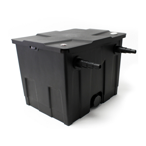
The WilTec pressure filter is an ideal filter system for your garden pond. The filter has more advantages:
•high cleaning capacity
•combine mechanical and biological (depending on model) filtering
•performant filter material
•built-in UVC unit and dirt indicator
•remains waterproof also by high pressure
•water delivery 3 m height (dependent on pump output which is connected)
•easy installation and maintenance of the filter
© by WilTec Wildanger Technik GmbH Item 50105, 50123, 50977–50980, 50121, 51042–51044 Page 7
http://www.WilTec.de
http://www.aoyue.eu 09 2021-1
http://www.teichtip.de
WilTec pond filter functions
The WilTec pond filter clarifies the water in 3 phases:
1. The first stage is mechanic. The visible particles of dirt are removed by means of a 3-layer filter
foam, arranged from coarse to fine.
2. The second stage is biologic. With the help of the so-called bio-balls (depending on model) the
settling of bio-organisms is stimulated. These bio-organisms remove the organic components
from the pond water (depending on model).
3. The third stage comprises a UVC water treatment. The UV light destroys swimming algae and
germs. The result is healthy water.
Commissioning
•The pressure filter should be placed at least at a 2-meter distance from the pond edge. The
water outlet back to pond should be placed max. 2 m over the filter cover (0,2 bar water pres-
sure!).
•The pump must be started first. The UVC lamp must not be operated as long as no water flows
through it. Do not use the UVC lamp if the lamp or the connections show damage signs. Do not
use the UVC-filter if there are people inside the water.
•The built-in UV filter temperature sensor stops the UVC lamp. After cooling down, it is automat-
ically re-started.
•The WilTec filter is delivered with all the necessary filter mats. Carefully wash the filter mats with
pond water before using. The bio-balls (depending on model) are placed at the bottom of the
filter, above put the grating with the protective tube for the UVC unit. Then put the filter foam
layers on it, arranged from fine to coarse. Put the cover lid on the housing and close the filter
with the supplied cramping bracket.
•If properly installed, the filter is waterproof up to a 0,5 bar working pressure. The power supply
has to be equipped with an earth leakage circuit breaker that does not exceed 30 mA.
© by WilTec Wildanger Technik GmbH Item 50105, 50123, 50977–50980, 50121, 51042–51044 Page 8
http://www.WilTec.de
http://www.aoyue.eu 09 2021-1
http://www.teichtip.de
Installing stepped hose tails
Place the coupling rings around the black hose tails, insert the flat gaskets in the coupling ring and screw
it on the water inlet and outflow connection. Screw the hose tails with the flat gaskets on the device.
Connecting to the water inlet
The pump is connected to the hose tail whose arrow is directed towards the filter. Use a hose diameter
which is exactly the same as the diameter of the pump outlet. Saw off the hose steps that you do not
need.
Connecting to the water outlet
The hose tail with the arrow showing away from filter is the outflow towards the pond. Connect a suitable
hose to the large diameter step of the hose tail and saw off the other hose steps. Use hose clamps to
prevent the loosening of the hoses.
Connecting to the cleaning outlet
To install a permanent drain hose to the cleaning connection (Clean), you have to unscrew/remove the
stepped tail to the cleaning connection (Clean), install the third stepped hose tail and connect a suitable
hose. In the filter operation, the cleaning connection or a connected drain hose must be always closed
and sealed with a hose tail (closure cap) and gasket seal, for safety means, in case the function switch
is accidentally set on “Clean.”
Attention! Do not operate the device
without water flow or
pump
fil-
te
r
!
© by WilTec Wildanger Technik GmbH Item 50105, 50123, 50977–50980, 50121, 51042–51044 Page 9
http://www.WilTec.de
http://www.aoyue.eu 09 2021-1
http://www.teichtip.de
Operating principle of the pressure filter
The pressure filter with the integrated UV lamp is a sealed filter system for biological and mechanical
cleaning of pond water.
CPF-180/CPF-250
CPF-2500-5000-10000-15000-20000-30000
© by WilTec Wildanger Technik GmbH Item 50105, 50123, 50977–50980, 50121, 51042–51044 Page 10
http://www.WilTec.de
http://www.aoyue.eu 09 2021-1
http://www.teichtip.de
CPF-280/CPF-500
Part
Name
Explanation
A
Water inlet
The pump is connected to the water inlet via a pressure hose.
B
Whirl system
The water permeates through the bio-filter materials due to the centrif-
ugal and gravitational forces.
C
Mechanical filter
Dirt particles are retained on the surface of the sponge filter before the
water flows towards the inner of the filter.
D
Biological cleaning
Microorganisms settle on the filter sponge pores. The blue and the
yellow filter sponge differ in size and density. This generates zones/ar-
eas through which the water flows at different speeds. In the zones/ar-
eas with a high flow speed (blue filter), mainly microorganisms settle
that convert ammonium to nitrate. In the areas in which the water flows
faster (yellow filter), mainly anaerobic microorganisms accumulate
that reduce the nitrate to nitrogen.
E
Pre-cleaning of the pond
water
When the water flows out, it is shortly exposed to the UV radiation
emitted by the UV lamp. As a result, germs, bacteria, and algae are
destroyed. The water circulates when flowing through the filter from
inside outwards.
F
Water discharge with
flow display
The cleaned water flows back into the pond.
G
Hose tails for rinsing water when on cleaning (CPF-180/CPF-250)
Flow indicator (CPF-280/CPF-500)
Hose tails for rinsing water when on cleaning (CPF-2500-5000-10000-15000-20000-30000)
H
The function switch changes between “filtration” and “clean filter.”
I
Flow indicator (CPF-
180/CPF-250)
When there is too much dirt on the sponge, the turbidimeter will
change from green to yellow to warn you to clean the sponge.
Cleaning crank (CPF-2500-5000-10000-15000-20000-30000)