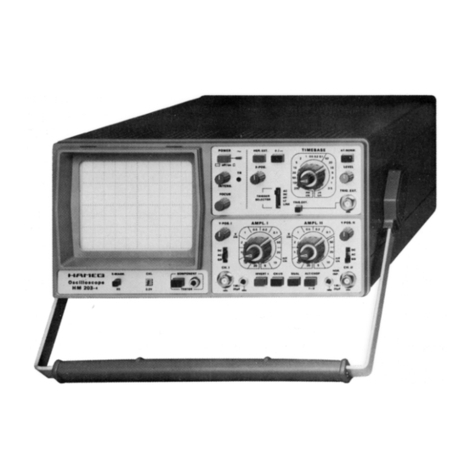
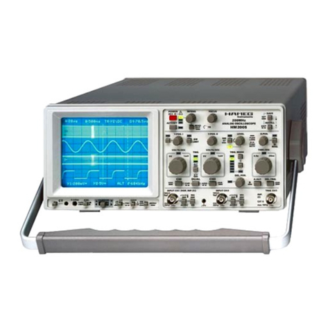
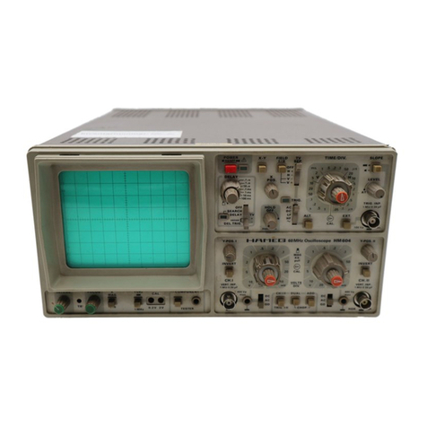
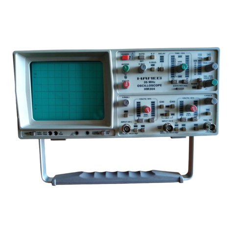
Hameg HM 303-4 User manual

Subject to change without notice 1
Operating Modes:CHI/II-TRIG.I/II, DUAL, ADD,
CHOP., INV.I/II and XY-Operation ................. 24
Triggering Checks.............................................. 25
Timebase........................................................... 25
Component Tester ............................................ 26
Trace Alignment ................................................ 26
Service Instructions
General.............................................................. 27
Instrument Case Removal................................. 27
Operating Voltages............................................ 27
Maximum and Minimum Brightness................. 27
Astigmatism control .......................................... 27
Trigger Threshold .............................................. 28
Trouble-Shooting the Instrument....................... 28
Replacement of Components and Parts ........... 28
Adjustments ...................................................... 28
Short Instruction ................................................ 29
Front Panel Elements, Front View . .................. 30
Table of contents
Oscilloscope datasheet
Operating Instructions
Symbols ............................................................ 6
General Information........................................... 6
Use of tilt handle ............................................... 6
Safety................................................................ 6
Operating conditions ......................................... 7
Warranty............................................................ 7
Maintenance ..................................................... 7
Protective Switch-Off........................................ 7
Power supply .................................................... 7
Type of signal voltage........................................ 8
Amplitude Measurements................................. 8
Time Measurements ......................................... 9
Connection of Test Signal ................................. 10
First Time Operation.......................................... 12
Trace Rotation TR.............................................. 12
Probe compensation and use............................ 12
Operating Modes of the Y Amplifier ................. 14
X-Y Operation .................................................... 15
Phase difference measurement
in DUAL mode............................................ 15
Measurement of an amplitude modulation ....... 16
Triggering and Timebase ................................... 16
Automatic Triggering ......................................... 17
Normal Triggering, Slope................................... 17
Trigger Coupling ................................................ 17
Triggering of Video Signals ................................ 17
Line Triggering................................................... 17
Alternate Triggering........................................... 17
External Triggering ............................................ 17
Trigger Indicator ................................................ 17
Function of variable HOLD OFF control............. 17
Y Overscanning Operation ................................ 18
Component Tester ............................................ 18
Test Patterns..................................................... 22
Test Instructions
General.............................................................. 23
Cathode-Ray Tube: Brightness, Focus,
Linearity, Raster Distortions......... 23
Astigmatism Check ........................................... 23
Symmetry and Drift of the Vertical Amplifier .... 23
Calibration of the Vertical Amplifier ................... 23
Transmission Performance
of the Vertical Amplifier ................................. 24
Oscilloscope
HM 303-4
GB
St. 170698/hüb/goRR

General information regarding the CE marking
HAMEG instruments fulfill the regulations of the EMC directive. The conformity test made by
HAMEG is based on the actual generic- and product standards. In cases where different limit
values are applicable, HAMEG applies the severer standard. For emission the limits for residential,
commercial and light industry are applied. Regarding the immunity (susceptibility) the limits for
industrial environment have been used.
The measuring- and data lines of the instrument have much influence on emmission and immunity
and therefore on meeting the acceptance limits. For different applications the lines and/or cables
used may be different. For measurement operation the following hints and conditions regarding
emission and immunity should be observed:
1. Data cables
For the connection between instruments resp. their interfaces and external devices, (computer,
printer etc.) sufficiently screened cables must be used. Without a special instruction in the manual
for a reduced cable length, the maximum cable length of a dataline must be less than 3 meters
long. If an interface has several connectors only one connector must have a connection to a cable.
Basicallyinterconnectionsmusthave a double screening.ForIEEE-buspurposesthedoublescreened
cables HZ72S and HZ72L from HAMEG are suitable.
2. Signal cables
Basically test leads for signal interconnection between test point and instrument should be as
short as possible. Without instruction in the manual for a shorter length, signal lines must be less
than 3 meters long.
Signal lines must screened (coaxial cable - RG58/U). A proper ground connection is required. In
combination with signal generators double screened cables (RG223/U, RG214/U) must be used.
3. Influence on measuring instruments.
Under the presence of strong high frequency electric or magnetic fields, even with careful setup of
the measuring equipment an influence of such signals is unavoidable.
Thiswillnot cause damage or put the instrument outofoperation. Small deviations of the measuring
value(reading)exceedingtheinstrumentsspecificationsmay result from such conditions in individual
cases.
December 1995
HAMEG GmbH

.
.
KONFORMITÄTSERKLÄRUNG
DECLARATION OF CONFORMITY
DECLARATION DE CONFORMITE
Name und Adresse des Herstellers HAMEG GmbH
Manufacturer´s name and address Kelsterbacherstraße 15-19
Nom et adresse du fabricant D - 60528 Frankfurt
HAMEG S.a.r.l.
5, av de la République
F - 94800 Villejuif
Die HAMEG GmbH / HAMEG S.a.r.l bescheinigt die Konformität für das Produkt
The HAMEG GmbH / HAMEG S.a.r.l herewith declares conformity of the product
HAMEG GmbH / HAMEG S.a.r.l déclare la conformite du produit
Bezeichnung / Product name / Designation:
Typ / Type / Type:
mit / with / avec:
Optionen / Options / Options:
mit den folgenden Bestimmungen / with applicable regulations / avec les directives suivantes
EMV Richtlinie 89/336/EWG ergänzt durch 91/263/EWG, 92/31/EWG
EMC Directive 89/336/EEC amended by 91/263/EWG, 92/31/EEC
Directive EMC 89/336/CEE amendée par 91/263/EWG, 92/31/CEE
Niederspannungsrichtlinie 73/23/EWG ergänzt durch 93/68/EWG
Low-Voltage Equipment Directive 73/23/EEC amended by 93/68/EEC
Directive des equipements basse tension 73/23/CEE amendée par 93/68/CEE
Angewendete harmonisierte Normen / Harmonized standards applied / Normes harmonisées utilisées
Sicherheit / Safety / Sécurité
EN 61010-1: 1993 / IEC (CEI) 1010-1: 1990 A 1: 1992 / VDE 0411: 1994
Überspannungskategorie / Overvoltage category / Catégorie de surtension: II
Verschmutzungsgrad / Degree of pollution / Degré de pollution: 2
Elektromagnetische Verträglichkeit / Electromagnetic compatibility / Compatibilité électromagnétique
EN 50082-2: 1995 / VDE 0839 T82-2
ENV 50140: 1993 / IEC (CEI) 1004-4-3: 1995 / VDE 0847 T3
ENV 50141: 1993 / IEC (CEI) 1000-4-6 / VDE 0843 / 6
EN 61000-4-2: 1995 / IEC (CEI) 1000-4-2: 1995 / VDE 0847 T4-2: Prüfschärfe / Level / Niveau = 2
EN 61000-4-4: 1995 / IEC (CEI) 1000-4-4: 1995 / VDE 0847 T4-4: Prüfschärfe / Level / Niveau = 3
EN 50081-1: 1992 / EN 55011: 1991 / CISPR11: 1991 / VDE0875 T11: 1992
Gruppe / group / groupe = 1, Klasse / Class / Classe = B
Datum /Date /Date Unterschrift / Signature /Signatur
Dr. J. Herzog
Technical Manager
Directeur Technique
Instruments
®
Oszilloskop/Oscilloscope/Oscilloscope
-
-
HM303-4
14.12.1995

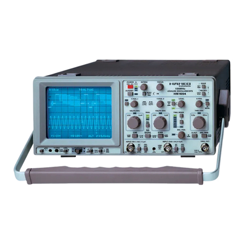
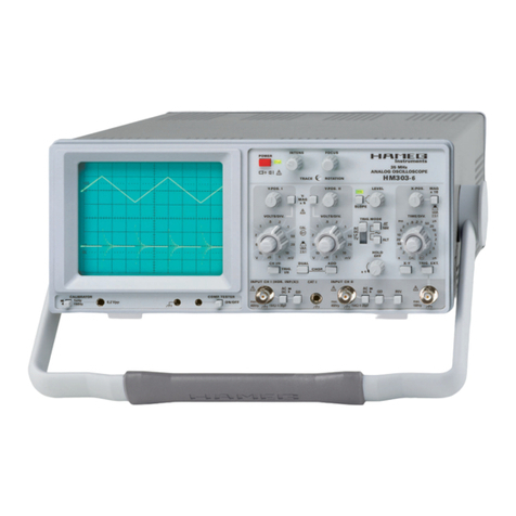
30MHz Standard Oscilloscope HM 303
Accessories supplied: Line cord, Operators Manual, 2 Probes 1:1/10:1
Screen photo of 1 MHz square wave signal
Screen photo of 50 and 100MHz
sinewavewith alternatetriggering
The new HAMEG HM303 oscilloscope succeeds the HM203 (over 170,000
soldworldwide).Thebandwidthhasbeenextended from20to30MHz,thesweep
rate increased to 10ns/div. and improvements added to the already legendary
HAMEGauto triggering system. TheHM303is the ideal instrument for waveform
display in the DC to 70MHz frequency range.
Akeyfeatureofthisoscilloscopeistheverticalamplifier'spulsefidelity,limiting
overshoot to only 1%. The HM303 offers a special fast rise time, 1kHz/1MHz
Calibratorpermittinghighqualityprobecompensationacrosstheentirefrequency
range to ensure probe-tip thru to display integrity. An Overscan Indicator assists
in vertical display amplitude and position adjustment.
The HM303 is capable of triggering on input waveforms over 100MHz and on
signal levels as small as 0.5 division. Alternate triggering mode enables the
display of two asynchronous signals simultaneously. An active Video Sync-
Separator permits detailed examination of complex TV signal inputs. A well
proven, built-in component tester is now equipped with a stabilized measuring
voltage. The use of a switching type of power supply minimizes both weight and
power consumption and universally accepts a wide range of input power line
voltages, without the requirement to change jumpers or switch positions. The
HM303's CRT is fully mu-metal shielded against outside magnetic fields.
HAMEGissettingnewprice/performancebreakthroughswiththeintroduction
ofthisfine oscilloscope.Thisperformance packed scopewilltempt allusersto run
it through its paces.
Dual Channel, DC to 30MHz, 1mV/div.; Overscan Indicator
Time Base: 0.5s to 10ns/div.; Variable Holdoff; Alternate Triggering
Triggering: DC-100MHz; Auto Peak to Peak; Active TV-Sync-Separator
Additional Features: Component Tester, 1kHz/1MHz Calibrator
OSCILLOSCOPES
Specifications
Vertical Deflection
Operating modes: Channel I or II separate,
bothChannels(alternated orchopped),
(Chopperfrequencyapprox.0.5MHz).
Sum ordifference with Ch. I and Ch. II
(bothchannelsinvertable).
XY-Mode: via channel I and channel II
Frequency range: 2xDCto30MHz(−3dB)
Risetime:<12ns.
Overshoot≤1%.
Deflection coefficients: 12 calibrated steps
from5mV/div.to 20V/div.(1-2-5sequence)
with variable 2.5:1 up to50V/div.
Accuracy in calibrated position: ±3%
Y-expansion x5 (calibrated)to1mV/div. (±5%)
in the frequency range from DC - 10MHz (–3dB)
Input impedance: 1MΩII20pF.
Inputcoupling:DC-AC-GD(ground).
Input voltage: max. 400V (DC + peak AC).
Triggering
Automatic: (peaktopeak) <20Hz-100MHz(≤0.5div.)
Normal with level control:DC-100MHz (≤0.5div.)
ALT. Triggering; LED indicator for trigger action
Slope:positiveor negative,
Sources: Channel I or II, CH. I alternating CH II,
line,external
Coupling: AC (10Hz to 100MHz),
DC(0 to 100MHz),
LF (0 to 1.5kHz)
Active TV-Sync-Separator (pos.andneg.)
External: ≥0.3Vp-p from 30Hz to 30MHz
Horizontal Deflection
Time coefficients:20 calibrated steps
from0.2s/div. - 0.1µs/div. in 1-2-5 sequence
Accuracy in calibrated position: ±3%.
Min.speedincl.variable2.5:1:0.5s/div.
with X-Mag. x10: ±5%; 10ns/div.: ±8%
Holdoff time: variable to approx. 10:1
BandwidthX-amplifier:0-3MHz(−3dB).
InputX-AmplifierviaChannelII,
(sensitivity see Channel II specification)
X-Y phase shift: <3° below 220kHz.
Component Tester
Test voltage: approx. 6Vrms(open circuit).
Test current: approx. 5mArms (shorted).
Test frequency: approx. 50Hz
Test connection: 2 banana jacks 4mm∅
One test lead is grounded (Safety Earth)
General Information
CRT:D14-364GY/123orER151-GH/-,
6" rectangular screen (8x10cm)
internalgraticule
Accelerationvoltage: approx2000V
Trace rotation: adjustable on front panel
Calibrator: square-wave generator (tr<4ns)
≈1kHz / 1MHz; Output: 0.2V ±1% and 2V
Linevoltage:100-240V AC±10%,50/60Hz
Power consumption: approx. 36 Watt at 50Hz.
Min./Max.ambienttemperature:−10°C...+40°C
Protective system: Safety class I (IEC 1010-1)
Weight:approx.5.6kg,color:techno-brown
Cabinet: W 285,H125,D380 mm
Lockabletilthandle
Subjecttochangewithoutnotice. 3/95

HZ20 Adaptor BNC to 4mm binding posts
HZ22 50ΩBNC Feed-through termination 1GHz, 1W
HZ23 Attenuator 2:1, BNC male to BNC female, for oscilloscope service only.
HZ24 Set of 4 BNC 50Ω attenuators; 3/6/10/20dB; 1GHz, 1W, incl. 1x HZ22
Test Cables
HZ32 Test cable BNC to single stacking banana plugs; 40 inch
HZ33 Coaxial cable BNC/BNC, 50Ω, 20 inch
HZ33S Coaxial cable BNC/BNC, 50Ω, 20 inch, insulated
HZ33W Coaxial cable BNC/BNC, 50Ω,20 inch, elbow
HZ34 Coaxial cable BNC/BNC, 50Ω, 40 inch
HZ34S Coaxial cable BNC/BNC, 50Ω, 40 inch, insulated
HZ72S IEEE-488-Bus-Cable,40inch.doubleshielded
HZ72L IEEE-488-Bus-Cable,60inch,doubleshielded
HZ84-2 Spare Printer Cable for HD148 (CE) and HM305 / 1007 (CE)
HZ84-3 Spare Printer Cable for combination of 25pole D-SUB / 26pole plastic male
Wide Band Probes with RF alignment
Type
Attenuation
Bandwidth Risetime InputImpedance Max.
Ratio InputVoltage
HZ36 1:1/10:1 10/100MHz <35/3.5ns 1/10MΩII57/12pF (10:1) 600V(DC+peak AC)
HZ51 10:1 150MHz <2.4ns 10MΩII12pF 600V(DC+peakAC)
HZ52 10:1 250MHz <1.4ns 10MΩII10pF 600V(DC+peakAC)
HZ53 100:1 100MHz <3.5ns 100MΩII4.5pF 1200V(DC+peakAC)
HZ54 1:1/10:1 10/150MHz <35/2.4ns 1/10MΩII57/12pF (10:1) 600V(DC+peak AC)
Special Probes
HZ38 DemodulatorProbe 0.1 - 500MHz max. 200V (DC)
HZ58
HighVoltageProbe,1000:1;R
i
approx.500MΩ;DC - 1MHz max.15kV(DC+peakAC)
HZ47 ViewingHood for OscilloscopesHM205,408, 604-1+2, 1005and1007
HZ48 Viewing Hood for Oscilloscopes 303, 304, 305, 604-3 and 1004
during transpor-
tation of an oscil-
loscope.Itismade
of a durable vinyl-
coated material
thatisdesignedto
withstand the
stress and wear
and tear of field
use.
Specifications:
Current range: 20A DC / 30A AC
Accuracy: ± 1% ± 2mA
Dielectric strength: 3.7kV, 50Hz, 1min.
Outputsensitivity: 100mV/A
Frequencyrange: DC-100kHz
Resolution: ±1mA
Loadimpedance: >100kΩ
Divers: BNC-cable,2m.
HZ 33
HZ 32
HZ34S
HZ72/S/L
HZ33W
HZ53
HZ54
HZ20
HZ22
HZ23
HZ24
HZ58
Accessories
supplied
HZ39 Spare Cable for HZ36
HZ57 Spare Cable for HZ51, HZ54
Spare-parts for modular probes only
Spare-part Kit HZ40
HZ96 Carrying Case
for oscilloscopes HM203, 205, 208,
408, 604, 1005 and 1007
HZ97 Carrying Case for HM303, 304,
305, 604-3, 1004 and HM5005 / 6 / 10.
The carrying case provides protection
HZ39
HZ57
HZ84-2
HZ36
HZ38
HZ51
HZ52
HZ40
HZ 56 AC/DC Current Probe
Utilising Hall Effect technology to provide a broad frequency response, the
probewillaccuratelymeasureAC,DCandcomplexwaveforms.Thecompact
clip-on design conforms to the IEC1010 safety standard and allows non-
intrusive measurement of current from 5mA to 30A peak to an accuracy of
±1%.Theprobegivesavoltageoutputdirectlyproportionaltothemeasured
current which is compatible with a wide range of measuring instruments.
Subject to change without notice 05/96
OSCILLOSCOPES

6Subject to change without notice
Symbols
See user's manual
Danger high voltage
Earth
General Information
This oscilloscope is easy to operate. The logical
arrangement of the controls allows anyone to quickly
become familiar with the operation of the instrument,
however, experienced users are also advised to read
through these instructions so that all functions are
understood.
Immediately after unpacking, the instrument should be
checked for mechanical damage and loose parts in the
interior.Ifthereistransportdamage,thesuppliermustbe
informed immediately. The instrument must then not be
put into operation.
Use of tilt handle
To view the screen from the best angle, there are three
differentpositions(C,D,E) for setting up the instrument. If
the instrument is set down on the floor after being carried,
the handle automatically remains in the upright carrying
position(A).
Inordertoplacetheinstrumentontoahorizontalsurface,the
handleshouldbeturnedtotheuppersideoftheoscilloscope
(C).FortheDposition(10°inclination),thehandleshouldbe
turnedtotheoppositedirectionofthecarryingpositionuntil
itlocksinplaceautomatically
underneaththeinstrument.For
theEposition(20°inclination),
thehandleshouldbepulledto
release it from the D position and swing backwards until it
locks once more.
The handle may also be set to a position for horizontal
carrying by turning it to the upper side to lock in the B
position.Atthesametime,theinstrumentmustbelifted,
because otherwise the handle will jump back.
Safety
This instrument has been designed and tested in accor-
dance with
IEC Publication 348, Safety Requirements
for Electronic Measuring Apparatu
s. The CENELEC
HD401regulationscorrespond tothisstandard.Ithas left
the factory in a safe condition. This instruction manual
contains important information and warnings which have
tobefollowedbytheusertoensuresafeoperationandto
retain the oscilloscope in a safe condition. The case,
chassis and all measuring terminals are connected to the
protective earth contact of the appliance inlet. The
instrument operates according to
Safety Class I
(three-
conductorpowercordwithprotectiveearthingconductor
andaplugwithearthingcontact).Themains/lineplugshall
onlybeinsertedinasocketoutletprovidedwithaprotective
earth contact. The protective action must not be negated
by the use of an extension cord without a protective
conductor.
Themains/lineplugshouldbeinsertedbeforeconnections
are made to measuring circuits.
The grounded accessible metal parts (case, sockets,
jacks) and the mains/line supply contacts (line/live, neu-
tral)oftheinstrumenthavebeentestedagainstinsulation
breakdown with 2200V DC.
Under certain conditions, 50Hz or 60Hz hum voltages
can occur in the measuring circuit due to the inter-
connection with other mains/line powered equipment
orinstruments.Thiscanbeavoidedbyusinganisolation
transformer (Safety Class II) between the mains/line
outlet and the power plug of the device being
investigated.
Most cathode-ray tubes develop X-rays. However,
the
dose equivalent rate falls far below the maximum
permissible value of 36pA/kg (0.5mR/h).
Whenever it is likely that protection has been impaired,
the instrument shall be made inoperative and be secured
against any unintended operation. The protection is likely
to be impaired if, for example, the instrument
−shows visible damage,
−fails to perform the intended measurements,
−has been subjected to prolonged storage under
unfavourable conditions (e.g. in the open or in moist
environments),
−hasbeensubjecttoseveretransportstress(e.g.inpoor
packaging).
Operating Instructions

Subject to change without notice 7
Operating conditions
The instrument has been designed for indoor use. The
permissible ambient temperature range during operation
is+10°C(+50°F)...+40°C(+104°F).Itmayoccasionallybe
subjected to temperatures between +10°C (+50°F) and -
10°C(+14°F)withoutdegradingitssafety.Thepermissible
ambienttemperaturerangeforstorageortransportationis
-40°C (-40°F) ... +70°C (+158°F). The maximum operating
altitude is up to 2200m (non-operating 15000m). The
maximum relative humidity is up to 80%. If condensed
water exists in the instrument it should be acclimatized
before switching on. In some cases (e.g. extremely cold
oscilloscope) two hours should be allowed before the
instrumentisputintooperation.Theinstrumentshouldbe
kept in a clean and dry room and must not be operated in
explosive, corrosive, dusty, or moist environments. The
oscilloscope can be operated in any position, but the
convection cooling must not be impaired. The ventilation
holes may not be covered. For continuous operation the
instrument should be used in the horizontal position,
preferably tilted upwards, resting on the tilt handle.
The specifications stating tolerances are only valid if
the instrument has warmed up for 30 minutes at an
ambient temperature between +15°C (+59°F) and
+30°C (+86°F). Values without tolerances are typical
for an average instrument.
Warranty
HAMEG warrants to its Customers that the products it
manufacturesandsellswillbefreefromdefectsinmaterials
and workmaship for a
period of 2 years
. This warranty
shall not apply to any defect, failure or damage caused by
improperuseorinadequatemaintenanceandcare.HAMEG
shall not obliged to provide service under this warranty to
repair damage resulting from attempts by personnel other
than HAMEG represantatives to install, repair, service or
modifytheseproducts.Inordertoobtainserviceunderthis
warranty,Customersmustcontactandnotifythedistributor
whohas sold the product. Each instrumentis subjected to
a quality test with 10 hour burn-in before leaving the
production.Practicallyallearlyfailuresaredetectedbythis
method. In the case of shipments by post, rail or carrier it
is recommended that the original packing is carefully
preserved. Transport damages and damage due to gross
negligencearenotcoveredbytheguarantee.Inthecaseof
acomplaint,alabelshouldbeattachedtothehousingofthe
instrumentwhichdescribesbrieflythefaultsobserved.Ifat
the same time the name and telephone number (dialing
code and telephone or direct number or department
designation)isstatedforpossiblequeries,thishelpstowards
speeding up the processing of guarantee claims.
Maintenance
Variousimportantpropertiesoftheoscilloscopeshouldbe
carefully checked at certain intervals. Only in this way is
it largely certain that all signals are displayed with the
accuracy on which the technical data are based. The test
methods described in the test plan of this manual can be
performed without great expenditure on measuring
instruments. However, purchase of the new HAMEG
scope tester HZ 60, which despite its low price is highly
suitablefortasksofthistype,isverymuchrecommended.
The exterior of the oscilloscope should be cleaned
regularly with a dusting brush. Dirt which is difficult to
remove on the casing and handle, the plastic and
aluminium parts, can be removed with a moistened
cloth (99% water +1% mild detergent). Spirit or was-
hing benzine (petroleum ether) can be used to remove
greasy dirt. The screen may be cleaned with water or
washingbenzine(butnotwithspirit(alcohol)orsolvents),
it must then be wiped with a dry clean lint-free cloth.
Under no circumstances may the cleaning fluid get into
the instrument. The use of other cleaning agents can
attack the plastic and paint surfaces.
Protective Switch-Off
This instrument is equipped with a switch mode power
supply. It has both overvoltage and overload protection,
which will cause the switch mode supply to limit power
consumption to a minimum. In this case a ticking noise
may be heard.
Power supply
Theoscilloscopeoperatesonmains/linevoltagesbetween
100VAC and 240VAC. No means of switching to different
input voltages has therefore been provided. The power
input fuses are externally accessible. The fuseholder is
located above the 3-pole power connector. The power
inputfusesareexternallyaccessible,iftherubberconector
is removed. The fuseholder can be released by pressing
itsplasticretainerswiththeaidofasmallscrewdriver.The
retainersarelocatedontherightandleftsideoftheholder
andmustbepressedtowardsthecenter.Thefuse(s)can
thenbereplacedandpressedinuntillockedonbothsides.
Useofpatchedfusesorshort-circuitingofthefuseholder
isnotpermissible;HAMEGassumesnoliabilitywhatsoever
foranydamagecausedasaresult,andallwarrantyclaims
become null and void.
Fuse type:
Size 5x20mm; 0.8A, 250V AC fuse;
must meet IEC specification 127,
Sheet III (or DIN 41 662
or DIN 41 571, sheet 3).
Time characteristic: time-lag.
Attention!
There is a fuse located inside the instrument within
the switch mode power supply:
Size 5x20mm; 0.5A, 250V AC fuse;
must meet IEC specification 127,
Sheet III (or DIN 41 662
or DIN 41 571, sheet 3).
Time characteristic: fast (F).
This fuse must not be replaced by the operator!

8Subject to change without notice
Type of signal voltage
WiththeHM303,mostrepetitivesignalsinthefrequency
range up to
at least 30MHz
(−3dB) can be examined.
Sinewavesignalsof50MHzaredisplayedwithaheightof
approx.50%(−6dB).Howeverwhenexaminingsquareor
pulse type waveforms, attention must be paid to the
harmonic content
of such signals. The repetition
frequency (fundamental frequency) of the signal must
therefore be significantly smaller than the upper limit
frequency of the vertical amplifier.
Displayingcompositesignalscanbedifficult,especiallyif
they contain no repetive higher amplitude content which
canbeusedfortriggering.Thisisthecasewithbursts,for
instance. To obtain a well-triggered display in this case,
the assistance of the
variable holdoff
and/or variable
time control may be required. Television
video signals
are relatively easy to trigger using the built-in
TV-Sync-
Separator (TV).
ForoptionaloperationasaDCorACvoltageamplifier,the
vertical amplifier input is provided with a DC/AC switch.
The DC position should only be used with a series-
connectedattenuator probe or at very low frequencies or
ifthemeasurementoftheDCvoltagecontentofthesignal
is absolutely necessary.
When displaying very low frequency pulses, the flat tops
may be sloping with AC coupling of the vertical amplifier
(AC limit frequency approx. 1.6 Hz for 3dB). In this case,
DC operation is preferred, provided the signal voltage is
not superimposed on a too high DC level. Otherwise a
capacitor of adequate capacitance must be connected to
the input of the vertical amplifier with DC coupling. This
capacitormusthaveasufficientlyhighbreakdownvoltage
rating. DC coupling is also recommended for the display
of logic and pulse signals, especially if the pulse duty
factor changes constantly. Otherwise the display will
moveupwardsordownwardsateachchange.Puredirect
voltages can only be measured with DC-coupling.
Amplitude Measurements
In general electrical engineering, alternating voltage data
normally refers to effective values (rms = root-mean-
squarevalue).However,forsignalmagnitudesandvoltage
designationsinoscilloscopemeasurements,thepeak-to-
peak voltage (Vpp) value is applied. The latter corresponds
totherealpotentialdifferencebetweenthemostpositive
and most negative points of a signal waveform.
If a sinusoidal waveform, displayed on the oscilloscope
screen, is to be converted into an effective (rms) value,
theresultingpeak-to-peak valuemustbedividedby 2x√2
= 2.83. Conversely, it should be observed that sinusoidal
voltagesindicatedinVrms (Veff)have2.83timesthepotential
difference in Vpp. The relationship between the different
voltagemagnitudescanbeseenfromthefollowingfigure.
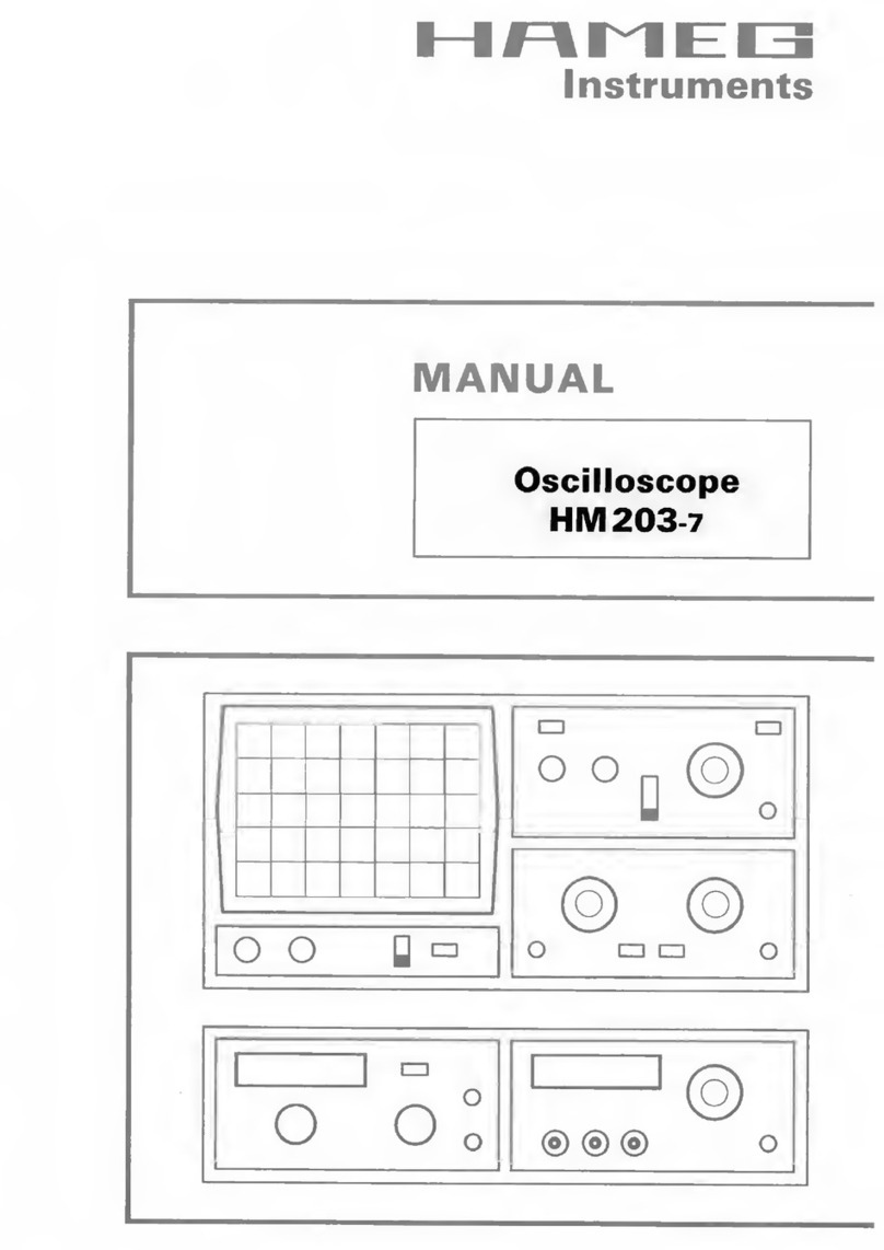
Voltage values of a sine curve
Vrms = effective value; Vp= simple peak or crest value;
Vpp = peak-to-peak value; Vmom = momentary value.
Theminimumsignalvoltagewhichmustbeappliedtothe
Y input for a trace of 1div. height is
1mV
pp
when the Y-
MAG. x5 pushbutton is depressed, the VOLTS/DIV.
switch is set to 5mV/div., and the vernier is set toCAL by
turning the
fine adjustment knob
of the VOLTS/DIV.
switchfullyclockwise.However,smallersignalsthanthis
may also be displayed. The
deflection coefficients
on
the input attenuators are indicated in mV/div. or V/div.
(peak-to-peak value).
The magnitude of the applied voltage is ascertained
by multiplying the selected deflection coefficient by
the vertical display height in div.
If an attenuator probe x10 is used, a further
multiplicationbyafactorof10isrequiredtoascertain
the correct voltage value.
Forexactamplitudemeasurements,thevariablecontrol
on the attenuator switch must be set to its calibrated
detentCAL. Whenturningthe variablecontrolccw, the
sensitivity will be reduced by a factor of 2.5.
Thereforeevery intermediatevalueis possiblewithin
the 1-2-5 sequence.
With direct connection to the vertical input, signalsup to
400Vpp may be displayed (attenuator set to 20V/div.,
variable control to left stop).
With the designations
H= display height in div.,
U= signal voltage in Vpp at the vertical input,
D=deflectioncoefficientinV/div.atattenuatorswitch,
the required value can be calculated from the two given
quantities:
However, these three values are not freely selectable.
Theyhavetobewithinthefollowinglimits(triggerthreshold,
accuracy of reading):
U = D · H U
D
H = U
H
D =
Vp Vrms Vmom
Vpp

Subject to change without notice 9
Hbetween 0.5 and 8div., if possible 3.2 to 8div.,
Ubetween 1mVpp and 160Vpp,
Dbetween 1mV/div. and 20V/div. in 1-2-5 sequence.
Examples:
Set deflection coefficient D= 50mV/div. 0.05V/div.,
observed display height H= 4.6div.,
required voltage U = 0.05·4.6 = 0.23Vpp.
Input voltage U= 5Vpp,
set deflection coefficient D= 1V/div.,
required display height H = 5:1 = 5div.
Signal voltage U = 230Vrms·2√2 = 651Vpp
(voltage > 160Vpp, with probe 10:1: U= 65.1Vpp),
desired display height H= min. 3.2div., max. 8div.,
max. deflection coefficient D = 65.1:3.2 = 20.3V/div.,
min. deflection coefficient D = 65.1:8 = 8.1V/div.,
adjusted deflection coefficient D = 10V/div.
The input voltage must not exceed 400V, indepen-
dent from the polarity.
If an AC voltage which is
superimposed on a DC voltage is applied, the maximum
peak value of both voltages must not exceed + or –400V.
So for AC voltages with a mean value of zero volt the
maximum peak to peak value is 800Vpp.
If attenuator probes with higher limits are used, the
probes limits are valid only if the oscilloscope is set
to DC input coupling.
If DC voltages are applied under
AC input coupling conditions the oscilloscope maximum
inputvoltagevalueremains400V.Theattenuatorconsists
ofaresistorintheprobeandthe1MΩinputresistorofthe
oscilloscope,whicharedisabled by theACinputcoupling
capacity when AC coupling is selected. This also applies
to DC voltages with superimposed AC voltages. It also
mustbenotedthatduetothecapacitiveresistanceofthe
ACinputcouplingcapacitor,theattenuationratiodepends
on the signal frequency. For sinewave signals with
frequencies higher than 40Hz this influence is negligible.
In the GD (ground coupling) setting, the signal path is
interrupted directly beyond the input. This causes the
attenuator to be disabled again, but now for both DC and
AC voltages.
WiththeabovelistedexceptionsHAMEG10:1probescan
beusedfor DCmeasurementsupto600V or ACvoltages
(with a mean value of zero volt) of 1200Vpp. The 100:1
probe HZ53 allows for 1200V DC or 2400Vpp for AC.
Itshouldbenoted that itsACpeak value is deratedathigher
frequencies.Ifanormalx10probeisusedtomeasurehigh
voltages there is the risk that the compensation trimmer
bridging the attenuator series resistor will break down
causingdamagetotheinputoftheoscilloscope.However,
if for example only the residual ripple of a high voltage is
tobe displayedonthe oscilloscope,anormal x10probeis
sufficient.Inthiscase,anappropriatehighvoltagecapacitor
(approx. 22-68nF) must be connected in series with the
input tip of the probe.
Total value of input voltage
The dotted line shows a voltage alternating at zero volt level. If super-
imposed on a DC voltage, the addition of the positive peak and the DC
voltage results in the max. voltage (DC + ACpeak).
With Y-POS. control (input coupling to GD) it is possible
to use a horizontal graticule line as
reference line for
ground potential
before the measurement. It can lie
below or above the horizontal central line according to
whether positive and/or negative deviations from the
ground potential are to be measured.
Time Measurements
As a rule, most signals to be displayed are periodically
repeating processes, also called periods. The number of
periodspersecondistherepetitionfrequency.Depending
onthe time base setting of theTIME/DIV. switch, one or
several signal periods or only a part of a period can be
displayed. The time coefficients are stated ins/div.,ms/
div. and µs/div. on the TIME/DIV.-switch. The scale is
accordingly divided into three fields.
The duration of a signal period or a part of it is
determined by multiplying the relevant time (hori-
zontal distance in div.) by the time coefficient set on
the TIME/DIV.-switch.
The variable time control (identified with an arrow
knob cap) must be in its calibrated position CAL.
(arrow pointing horizontally to the right).
With the designations
L= displayed wave length in div. of one period,
T= time in seconds for one period,
F= recurrence frequency in Hz of the signal,
Tc= time coefficient in s/div. on timebase switch and
therelationF=1/T,thefollowingequationscanbestated:
With depressed X-MAG. (x10) pushbutton the T
c
value must be divided by 10.
However, these four values are not freely selectable.
They have to be within the following limits:
Lbetween 0.2 and 10div., if possible 4 to 10div.,
Tbetween 0.01µs and 2s,
Fbetween 0.5Hz and 30MHz,
Tcbetween 0.1µs/div. and 0.2s/div. in 1-2-5 sequence
(with X-MAG. (x10) in out position), and
Tcbetween 10ns/div. and 20ms/div. in 1-2-5 sequence
(with pushed X-MAG. (x10) pushbutton).
DC + ACpeak = 400Vmax.
DC
AC time
DC
peak
AC
Voltage
T
Tc
L = T
L
Tc=
T = L · Tc
L = 1
F · Tc
1
L · Tc
F = Tc= 1
L · F

10 Subject to change without notice
Examples:
Displayed wavelength L= 7div.,
set time coefficient Tc= 0.1µs/div.,
required period T= 7x0.1x10−6= 0.7µs
required rec. freq. F = 1:(0.7x10⁻⁶) = 1.428MHz.
Signal period T= 1s,
set time coefficient Tc= 0.2s/div.,
required wavelength L = 1:0.2 = 5div..
Displayed ripple wavelength L= 1div.,
set time coefficient Tc= 10ms/div.,
required ripple freq. F = 1:(1x10x10−3) = 100Hz.
TV-line frequency F= 15625Hz,
set time coefficient Tc= 10µs/div.,
required wavelength L = 1:(15 625x10−5) = 6.4div..
Sine wavelength L= min. 4div., max. 10div.,
Frequency F= 1kHz,
max. time coefficient Tc= 1:(4x10³) = 0.25ms/div.,
min. time coefficient Tc= 1:(10x103) = 0.1ms/div.,
set time coefficient Tc= 0.2ms/div.,
required wavelength L= 1:(103x0.2x10−3) = 5div.
Displayed wavelength L= 0.8div.,
set time coefficient Tc= 0.5µs/div.,
pressed X-MAG. (x10) button:
Tc= 0.05µs/div.,
required rec. freq. F = 1:(0.8x0.05x10−6) = 25MHz,
required period T = 1:(25x10−6) = 40ns.
If the time is relatively short as compared with the
complete signal period, an expanded time scale should
alwaysbeapplied(X-MAG. (x10) buttonpressed).In this
case, the ascertained time values have to be divided by
10
. The time interval of interest can be shifted to the
screen center using the X-POS. control.
Wheninvestigatingpulseorsquarewaveforms,thecritical
feature is the
risetime of the voltage step
. To ensure
that transients, ramp-offs, and bandwidth limits do not
unduly influence the measuring accuracy, the risetime is
generallymeasuredbetween
10%
and
90%
ofthevertical
pulse height. For measurement adjust the Y attenuator
switch with its variable control together with theY-POS.
control so that the pulse height is precisely aligned with
the 0 and 100% lines of the internal graticule. The 10%
and 90% points of the signal will now coincide with the
10% and 90% graticule lines.
The risetime is given by
theproductofthehorizontaldistanceindiv.between
thesetwocoincidencepointsandthetimecoefficient
setting
. If X x10 magnification is used, this product must
be divided by 10. The
fall time
of a pulse can also be
measured by using this method.
The following figure shows correct positioning of the
oscilloscope trace for accurate risetime measurement.
tr= √ttot2- tosc2- tp2
tr= √ 322- 122- 22= 29.6ns
350
B
tr= 350
tr
B =
With a time coefficient of 0.2µs/div. and pushed X-MAG
x10buttontheexampleshownintheabovefigureresults
in a measured total risetime of
ttot = 1.6div·0.2µs/div.:10 = 32ns
Whenveryfastrisetimesarebeingmeasured,therisetimes
of the oscilloscope amplifier and of the attenuator probe
has to be deducted from the measured time value. The
risetimeofthesignalcanbecalculatedusingthefollowing
formula.
Inthisttot isthetotalmeasuredrisetime,tosc istherisetime
of the oscilloscope amplifier (approx. 12ns), and tp the
risetime of the probe (e.g. = 2ns). If ttot is greater than
100ns, then ttot can be taken as the risetime of the pulse,
and calculation is unnecessary.
Calculation of the example in the figure above results in a
signal risetime
The measurement of the rise or fall time is not limited to
the trace dimensions shown in the above diagram. It is
only particularly simple in this way. In principle it is
possible to measure in any display position and at any
signalamplitude.It isonlyimportantthatthe full heightof
the signal edge of interest is visible in its full length at not
too great steepness and that the horizontal distance at
10% and 90% of the amplitude is measured. If the edge
showsroundingorovershooting,the100%shouldnotbe
related to the peak values but to the mean pulse heights.
Breaks or peaks (glitches) next to the edge are also not
takenintoaccount.Withveryseveretransientdistortions,
theriseandfalltimemeasurementhaslittlemeaning.For
amplifiers with approximately constant group delay
(therefore good pulse transmission performance) the
following numerical relationship between rise time tr (
in
ns
) and bandwidth B(
in MHz
) applies:
Connection of Test Signal
Caution:
Whenconnectingunknownsignalstotheoscillo-
scope input, always use automatic triggering and set the
DC-ACinputcouplingswitchtoAC.Theattenuatorswitch
should initially be set to 20V/div.

Subject to change without notice 11
Sometimes the trace will disappear after an input signal
has been applied. The attenuator switch must then be
turned back to the left, until the vertical signal height is
only 3-8div. With a signal amplitude greater than 160Vpp,
an attenuator probe must be inserted before the vertical
input. If, after applying the signal, the trace is nearly
blanked, the period of the signal is probably substantially
longer than the set value on the TIME/DIV. switch. It
should be turned to the left to an adequately larger time
coefficient.
The signal to be displayed can be connected directly to
the Y-input of the oscilloscope with a shielded test
cable such as HZ 32 or HZ 34, or reduced through a x10
or x100 attenuator probe. The use of test cables with
high impedance circuits is only recommended for
relatively low frequencies (up to approx. 50 kHz). For
higher frequencies, the signal source must be of low
impedance,i.e.matchedtothecharacteristicresistance
of the cable (as a rule 50 Ohm). Especially when
transmitting square and pulse signals, a resistor equal
to the characteristic impedance of the cable must also
be connected across the cable directly at the Y-input of
the oscilloscope. When using a 50Ωcable such as the
HZ34,a50ΩthroughterminationtypeHZ22isavailable
from HAMEG. When transmitting square signals with
short rise times, transient phenomena on the edges
and top of the signal may become visible if the correct
termination is not used. A terminating resistance is
sometimes recommended with sine signals as well.
Certain amplifiers, generators or their attenuators
maintain the nominal output voltage independent of
frequency only if their connection cable is terminated
with the prescribed resistance. Here it must be noted
that the terminating resistor HZ22 will only dissipate a
maximum of 2 Watts. This power is reached with 10
Vrms or at 28.3 V
pp
with sine signal.
If a x10 or x100 attenuator probe is used, no termination
isnecessary.Inthiscase,theconnectingcableismatched
directly to the high impedance input of the oscilloscope.
When using attenuators probes, even high internal
impedance sources are only slightly loaded (approx. 10
MΩII 16 pF or 100 MΩII 9 pF with HZ 53). Therefore, if
thevoltagelossduetotheattenuationoftheprobecanbe
compensated by a higher amplitude setting, the probe
should always be used. The series impedance of the
probeprovidesacertainamountofprotectionfortheinput
of the vertical amplifier. Because of their separate
manufacture, all attenuator probes are only partially
compensated,thereforeaccuratecompensationmustbe
performedontheoscilloscope(see“Probecompensation
page M7).
Standard attenuator probes on the oscilloscope normally
reduce its bandwidth and increase the rise time. In all
cases where the oscilloscope bandwidth must be fully
utilized (e.g. for pulses with steep edges) we strongly
adviseusingthe
modularprobesHZ 51
(x10)
HZ52
(x10
HF) and
HZ 54
(x1 and x10. This can save the purchase
of an oscilloscope with larger bandwidth and has the
advantage that defective components can be ordered
from HAMEG and replaced by oneself. The probes
mentioned have a HF-calibration in addition to low
frequency calibration adjustment. Thus a group delay
correctiontotheupperlimitfrequencyoftheoscilloscope
is possible with the aid of an 1MHz calibrator, e.g. HZ60.
Infactthebandwidthandrisetimeoftheoscilloscopeare
not noticably changed with these probe types and the
waveform reproduction fidelity can even be improved
because the probe can be matched to the oscilloscopes
individual pulse response.
If a x10 or x100 attenuator probe is used, DC input
coupling must always be used at voltages above
400V
. With AC coupling of low frequency signals, the
attenuation is no longer independent of frequency,
pulses can show pulse tilts. Direct voltages are
suppressed but load the oscilloscope input coupling
capacitor concerned. Its voltage rating is max. 400 V
(DC + peak AC). DC input coupling is therefore of quite
specialimportancewithax100attenuationprobewhich
usually has a voltage rating of max. 1200 V (DC + peak
AC). A
capacitor
of corresponding capacitance and
voltage rating may be connected in
series with the
attenuator
probeinput forblockingDCvoltage (e.g.for
hum voltage measurement).
Withallattenuatorprobes,the
maximumACinputvoltage
must be
derated
with frequency usually above 20kHz.
Thereforethederating curveoftheattenuator probetype
concerned must be taken into account.
The selection of the ground point on the test object is
importantwhendisplayingsmallsignalvoltages.Itshould
always be as close as possible to the measuring point. If
this is not done, serious signal distortion may result from
spurious currents through the ground leads or chassis
parts. The ground leads on attenuator probes are also
particularly critical. They should be as short and thick as
possible. When the attenuator probe is connected to a
BNC-socket, a BNC-adapter, which is often supplied as
probe accessory, should be used. In this way ground and
matching problems are eliminated.
Hum or interference appearing in the measuring circuit
(especially when a small deflection coefficient is used) is
possiblycausedbymultiplegroundingbecauseequalizing
currents can flow in the shielding of the test cables
(voltage drop between the protective conductor
connections,causedbyexternalequipmentconnectedto
the mains/line, e.g. signal generators with interference
protection capacitors).

12 Subject to change without notice
First Time Operation
Before applying power
to the oscilloscope it is recom-
mended that the following simple procedures are
performed:
• Check that all pushbuttons are in the
out
position, i.e.
released.
•
Rotatethevariable controlswitharrows,i.e.TIME/DIV.
variable control, CH.I and CH.II attenuator variable
controls, and HOLD OFF control to their calibrated
detent.
• Set all controls with marker lines to their midrange
position (marker lines pointing vertically).
• TheTRIG.selectorleverswitchintheX-fieldshouldbe
set to the position uppermost.
• Both GD input coupling pushbutton switches forCH.I
andCH.IIintheY-fieldshouldbesettotheGDposition.
SwitchontheoscilloscopebydepressingtheredPOWER
pushbutton. An LED will illuminate to indicate working
order.Thetrace,displayingonebaseline,shouldbevisible
after a short warm-up period of approx. 10 seconds.
AdjustY-POS.IandX-POS.controlstocenterthebaseline.
Adjust INTENS. (intensity) and FOCUS controls for
mediumbrightness and optimum sharpness of thetrace.
The oscilloscope is now ready for use.
If only a spot appears (
CAUTION!
CRT phosphor can be
damaged), reduce the intensity immediately and check
that theXY pushbutton is in the released(out)position.If
the trace is not visible, check the correct positions of all
knobsandswitches(particularlyAT/NORM.buttoninout
position).
Toobtainthemaximumlifefromthecathode-raytube,the
minimumintensitysettingnecessaryforthemeasurement
in hand and the ambient light conditions should be used.
Particular care is required when a single spot is
displayed,
as a very high intensity setting may cause
damage to the fluorescent screen of the CRT. Switching
theoscilloscope off and on at short intervals stresses the
cathode of the CRT and should therefore be avoided.
Theinstrumentissodesignedthatevenincorrectoperation
will not cause serious damage. The pushbuttons control
only minor functions, and it is recommended that before
commencement of operation all pushbuttons are in the
“out”position.Afterthisthepushbuttonscanbeoperated
depending upon the mode of operation required.
TheHM303acceptsallsignalsfromDC(directvoltage)up
to a frequency of at least 30MHz (−3dB). For sinewave
voltages the upper frequency limit will be 50MHz (−6dB).
However, in this higher frequency range the vertical
display height on the screen is limited to approx. 4-5div.
Thetimeresolution posesnoproblem.Forexample, with
50MHzandthefastest adjustable sweep rate(10ns/div.),
one cycle will be displayed every 2div. The tolerance on
indicated values amounts to ±3% in both deflection
directions. All values to be measured can therefore be
determined relatively accurately.
However, from approximately 10MHz upwards the
measuringerrorwillincreaseasa resultoflossofgain.At
18MHz this reduction is about 10%. Thus, approximately
11% should be added to the measured voltage at this
frequency. As the bandwidth of the amplifiers may differ
slightly(normallybetween30and35MHz),themeasured
values in the upper frequency range cannot be defined
exactly.Additionally,asalreadymentioned,forfrequencies
above 30MHz the dynamic range of the display height
steadily decreases. The vertical amplifier is designed so
that the transmission performance is not affected by its
own overshoot.
Trace Rotation TR
In spite of Mumetal-shielding of the CRT, effects of
the earths magnetic field on the horizontal trace
position cannot be completely avoided. This is
dependent upon the orientation of the oscilloscope
on the place of work. A centred trace may not align
exactlywiththehorizontalcenterlineofthegraticule.
A few degrees of misalignment can be corrected by a
potentiometer accessible through an opening on the
front panel marked TR.
Probe compensation and use
To display an undistorted waveform on an oscilloscope,
the probe must be matched to the individual input
impedance of the vertical amplifier.
Forthispurposeasquarewavesignalwithaveryfastrise
time and minimum overshoot should be used, as the
sinusoidal contents cover a wide frequency range. The
frequency accuracy and the pulse duty factor are not of
such importance.
The built-in calibration generator provides a square wave
signal with a very fast risetime (<4ns), and switch-
selectable frequencies of approx. 1kHz and 1MHz from
two output sockets below the CRT screen.
This signal should not be used for frequency cali-
bration!

Subject to change without notice 13
T3: alters the middle frequencies
T4: alters the leading edge
T5: alters the lower frequencies
(LF)
(LF)
Oneoutputprovides0.2Vpp ±1%(tr<4ns)for10:1probes,
and the other 2Vpp ±1% for 100:1 probes. When the
attenuator
switchesaresetto5mV/divverticaldeflection
coefficient, these calibration voltages correspond to a
screen amplitude of
4div
.
Theoutputsocketshaveaninternaldiameterof4.9mmto
accommodatetheinternationallyacceptedshieldingtube
diameterofmodernModularProbesandF-seriesslimline
probes.Onlythistypeofconstructionensurestheextremly
short ground connections which are essential for an
undistortedwaveformreproductionofnon-sinusoidalhigh
frequency signals.
Adjustment at 1kHz
The C-trimmer adjustment compensates the capacitive
loading on the oscilloscope input (approx. 20 pF for the
HM 303). By this adjustment, the capacitive division
assumes the same ratio as the ohmic voltage divider to
ensurethesamedivisionratioforhighandlowfrequencies,
asforDC.(For1:1probesorswitchableprobessetto1:1,
thisadjustmentisneitherrequirednorpossible).Abaseline
exactly parallel to the horizontal graticule lines is a major
conditionforaccurateprobeadjustments.(Seealso“Trace
rotation TR”).
Connect the probes (Types HZ51, 52, 53, 54, or HZ36) to
theCH.I input. All pushbuttons should be released (in the
out position). Set input coupling to DC, the attenuator to
5 mV/div., andTIME/DIV. switch to0.2 ms/div., and all
variable controls to CAL. position. Plug the the probe tip
into the appropriate calibrator output socket, i.e. 10:1
probes into the 0.2V socket, 100:1 probes into the 2V
socket.
1 kHz
incorrect correct incorrect
Approximately2completewaveformperiodsaredisplayed
on the CRT screen. Now the compensation trimmer has to
be adjusted. Normally, this trimmer is located in the probe
head.Onthe100:1probeHZ53,however,itislocatedinthe
connecting box at the other end of the cable. Adjust the
trimmer with the insulating screw driver provided until the
tops of the square wave signal are exactly parallel to the
horizontal graticule lines (see 1 kHz diagram). The signal
height should then be 4 div. ± 0.12div. (= 3 %). During this
adjustment, the signal edges will remain invisible.
Adjustment at 1MHz
Probes HZ51, 52 and 54 can also be HF-compensated.
They incorporate resonance de-emphasing networks (R-
trimmer in conjunction with inductances and capacitors)
which permit probe compensation in the range of the
upperfrequencylimitoftheverticaloscilloscopeamplifier.
HZ51, HZ54
Only this compensative adjustment ensures optimum
utilisation of the full bandwidth, together with constant
group delay at the high frequency end, thereby reducing
characteristic transient distortion near the leading edge
(e.g. overshoot, rounding, ringing, holes or bumps) to an
absolute minimum.
Using the probes HZ51, 52 and 54, the full bandwidth of
the HM303 can be utilized without risk of unwanted
waveform distortion.
Prerequisite for this HF compensation is a square wave
generator with fast risetime (typically 4 ns), and low
outputimpedance(approx.50Ω),providing0.2Vand2Vat
afrequencyofapprox. 1MHz. Thecalibratoroutputofthe
HM303 meets these requirements when the CAL.
pushbutton is depressed.
Connect the probe to CH.I input. Depress the CAL.
pushbutton for 1MHz. All other pushbuttons should be
released(outposition). Set the CH.I input couplingtoDC,
attenuator switch to 5mV/div, and TIME/DIV. switch to
0.2µs/div. Set all variable controls to CAL. position.
Insert the probe tip into the output socket marked 0.2V.
A waveform will be displayed on the CRT screen, with
leading and trailing edges clearly visible. For the HF-
adjustment now to be performed, it will be necessary to
observetherisingedge as wellastheupperleftcorner of
the pulse top. The connecting boxes of the HZ51 and
HZ54containoneR-trimmerscreweach,whilethatofthe
HZ52providesthree.TheseR-trimmershavetobeadjusted
such that the beginning of the pulse is as straight as
possible. Overshoot or excessive rounding are unaccept-
able. This is relatively easy on the HZ51 and HZ54, but
slightlymoredifficultontheHZ52.Therisingedgeshould
be as steep as possible, with a pulse top remaining as
straight and horizontal as possible.
On the HZ52, each of the three trimmers has a clearly
defined area of influence on the waveform shape (see
Fig.), offering the added advantage of being able to
straighten out waveform abberations near the leading
edge.

14 Subject to change without notice
AftercompletionoftheHF-adjustment,thesignalamplitude
displayed on the CRT screen should have the same value
as during the 1kHz adjustment.
Probes other than those mentioned above, normally
have a larger tip diameter and may not fit into the
calibrator outputs. Whilst it is not difficult for an
experienced operator to build a suitable adapter, it
should be pointed out that most of these probes have
aslowerrisetimewiththeeffectthatthetotalbandwidth
of scope together with probe may fall far below that of
theHM303.Furthermore, the HF-adjustment feature is
nearly always missing so that waveform distortion can
not be entirely excluded.
The adjustment sequence must be followed in the order
described, i.e. first at 1kHz, then at 1MHz. The calibrator
frequencies should not be used for timebase calibration.
The pulse duty cycle deviates from 1:1 ratio.
Prerequisites for precise and easy probe adjustments, as
well as checks of deflection coefficients, are straight
horizontal pulse tops, calibrated pulse amplitude, and
zero-potentialatthepulsebase.Frequencyanddutycycle
are relatively uncritical. For interpretation of transient
response, fast pulse risetimes and low-impedance
generator outputs are of particular importance.
Providing these essential features, as well as switch-
selectableoutput-frequencies,thecalibratoroftheHM303
can, under certain conditions, replace expensive
squarewave generators when testing or compensating
wideband-attenuators or -amplifiers. In such a case, the
input of an appropriate circuit will be connected to one of
the CAL.-outputs via a suitable probe.
Thevoltageprovidedatahigh-impedanceinput(1MΩII15-
50pF) will correspond to the division ratio of the probe
used (10:1 = 20mVpp, 100:1 = also 20mVpp from 2V
output). Suitable probes are HZ51, 52, 53, and 54.
Operating modes of the vertical amplifiers
Theverticalamplifierissettothedesiredoperatingmode
byusingthe3pushbuttons(CHI/II,DUALandADD)inthe
Y field of the front panel. For
Mono
mode all 3 buttons
mustbeintheirreleasedpositions;onlychannelIcanthen
beoperated.ThebuttonCHI/II-TRIG.I/IImustbedepressed
in mono mode for Channel II. The internal triggering is
simultaneously switched over to Channel II with this
button.
If the DUAL button is depressed, both channels are
working. Two signals can be displayed together in this
button position (alternate mode) if the time-base setting
and the repetition frequency of the signal are suited. This
mode is not suitable for displaying very slow-running
processes.Thedisplaythenflickerstoomuchoritappears
to jump. If the ADD button is depressed
in addition
to
DUAL, both channels are switched over constantly at a
highfrequencywithinasweepperiod(CHOPmode).Low
frequency signals
below 1kHz, or with periods longer
than 1ms
are then also displayed without flicker. CHOP
modeisnotrecommendedforsignalswithhigherrepetition
frequencies.
If only the ADD button is depressed, the signals of both
channels are algebraically added (±I ±II). Whether the
resultingdisplayshowsthe
sum
or
difference
isdependent
onthephaserelationshiporthepolarityofthesignals
and
on the positions of the INVERT buttons.
In-phase input voltages:
Both INVERT CH.I
and
INVERT CH.II buttons
released or depressed = sum.
Only one INVERT button depressed = difference.
Antiphase input voltages:
Both INVERT buttons released or depressed
= difference.
INVERTCH.I
or
INVERTCH.IIbuttondepressed=sum.
IntheADDmodetheverticaldisplaypositionisdependent
upon the Y-POS. setting of
both
channels. The same
attenuator switch position is normally used for both
channels with algebraic addition.
PleasenotethattheY-POS.settingsareaddedtoobutare
not affected by the INVERT pushbuttons.
Differential measurement
techniques allow direct
measurement of the voltage drop across floating
components (both ends above ground). Two identical
probesshouldbe used for both vertical inputs. In orderto
avoidgroundloops,useaseparategroundconnectionand
do not use the probe ground leads or cable shields.
incorrect incorrect
correct
Adjustment
1MHz

Subject to change without notice 15
X-Y Operation
For
X-Y operation
, the pushbutton in the X field marked
XY must be depressed. The X signal is then derived from
the
INPUT CH II
(X).
The calibration of the X signal
during X-Y operation is determined by the setting of
the Channel II input attenuator and variable control.
This means that the sensitivity ranges and input
impedances are identical for both the X and Y axes.
However, the Y-POS.II control is disconnected in this
mode. Its function is taken over by theX-POS. control. It
is important to note that the X-MAG. (x10) facility,
normally used for expanding the sweep, should not be
operatedin theX-Ymode.Itshouldalsobe notedthatthe
bandwidthoftheXamplifieris≥3MHz(−3dB),andtherefore
an increase in phase difference between both axes is
noticeable from 50kHz upwards.
TheinversionoftheX-inputsignalusingtheINVERTCH.II
button is not possible.
Lissajous figures can be displayed in the X-Y mode for
certain measuring tasks:
−Comparingtwosignalsofdifferentfrequencyorbringing
one frequency up to the frequency of the other signal.
Thisalsoappliesforwholenumbermultiplesorfractions
of the one signal frequency.
−Phase comparison between two signals of the same
frequency.
Phase comparison with Lissajous figures
The following diagrams show two sine signals of the
samefrequencyandamplitudewithdifferentphaseangles.
Calculationofthephaseangleorthephaseshiftbetween
theX and Y input voltages (after measuring the distances
aand bon the screen) is quite simple with the following
formula, and a pocket calculator with trigonometric
functions. Apart from the reading accuracy, the signal
height has no influence on the result.
The following must be noted here:
−Because of the periodic nature of the trigonometric
functions, the calculation should be limited to angles
≤90°. However here is the advantage of the method.
−Do not use a too high test frequency. The phase shift
ofthetwooscilloscopeamplifiersoftheHM303inthe
X-Y mode can exceed an angle of 3° above 120 kHz.
−Itcannotbeseenasamatterofcoursefromthescreen
display if the test voltage leads or lags the reference
voltage. A CR network before the test voltage input of
the oscilloscope can help here. The 1 MΩinput resis-
tance can equally serve as R here, so that only a
suitablecapacitorCneedstobeconnectedinseries.If
theaperturewidthoftheellipseisincreased(compared
with C short-circuited), then the test voltage leads the
reference voltage and vice versa. This applies only in
theregionupto90°phaseshift.ThereforeCshouldbe
sufficientlylargeandproduceonlyarelativelysmalljust
observable phase shift.
Should both input voltages be missing or fail in the
X-Y mode, a very bright light dot is displayed on the
screen. This dot can burn into the phosphor at a too
highbrightness setting (INTENS.knob) which causes
either a lasting loss of brightness, or in the extreme
case, complete destruction of the phosphor at this
point.
Phase difference measurement
in DUAL mode
A larger phase difference between two input signals of
the same frequency and shape can be measured very
simply on the screen in Dual mode (DUAL button
depressed). The time base should be triggered by the
reference signal (phase position 0). The other signal can
then have a leading or lagging phase angle. Alternate
mode should be selected for frequencies ≥1 kHz; the
Chop mode is more suitable for frequencies <1 kHz (less
flickering).
For greatest accuracy adjust not much more than one
periodandapproximately the sameheightofbothsignals
on the screen. The variable controls for amplitude and
time base and the LEVEL knob can also be used for this
adjustment without influence on the result. Both base
lines are set onto the horizontal graticule center line with
the Y-POS. knobs before the measurement. With
sinusoidal signals, observe the zero (crossover point)
transitions; the sine peaks are less accurate. If a sine
signalis noticeably distorted by even harmonics, or if ad.c.
voltageispresent,AC couplingisrecommendedfor
both
channels. If it is a question of pulses of the same shape,
read off at steep edges.
a
b2
√( )
cos ϕϕ
ϕϕ
ϕ = 1
−−
−−
−
a
b
ϕϕ
ϕϕ
ϕ= arc sin
a
b
sin ϕϕ
ϕϕ
ϕ =

16 Subject to change without notice
Phase difference measurement in DUAL mode
t
= horizontal spacing of the zero transitions in div.
T
= horizontal spacing for one period in div.
In the example illustrated,
t
= 3div. and
T
= 10div. The
phase difference in degrees is calculated from
Relatively small phase angles at not too high frequencies
can be measured more accurately in the X-Y mode with
Lissajous figures.
Measurement of an amplitude modulation
The momentary amplitude u at time t of a HF-carrier
voltage,whichis amplitude modulated without distortion
by a sinusoidal AF voltage, is in accordance with the
equation
u= U
T
·sin
ΩΩ
ΩΩ
Ω
t+ 0,5m· U
T
· cos(
Ω−ωΩ−ω
Ω−ωΩ−ω
Ω−ω
)t
−−
−−
−
0,5m ·U
T
· cos(
ΩΩ
ΩΩ
Ω
+
ωω
ωω
ω
)t
where
U
T
= unmodulated carrier amplitude
ΩΩ
ΩΩ
Ω
=
2
ππ
ππ
π
F
= angular carrier frequency
ωω
ωω
ω
=
2
ππ
ππ
π
f
= modulation angular frequency
m
= modulation factor (i.a. ≤1 100%).
Thelowersidefrequency
F
−
f
andtheuppersidefrequency
F+f
arisebecauseofthemodulationapartfromthecarrier
frequency
F
.
Amplitude and frequency spectrum for AM display (m= 50%)
Thedisplayoftheamplitude-modulatedHFoscillationcan
beevaluatedwiththeoscilloscopeprovidedthefrequency
spectrum is inside the oscilloscope bandwidth. The time
base is set so that several wave of the modulation
frequency are visible. Strictly speaking, triggering should
be external with modulation frequency (from the AF
generatororademodulator).However,internaltriggering
isfrequentlypossible with normaltriggering(AT/NORM.
button depressed) using a suitable LEVEL setting and
possibly also using the time variable adjustment.
Oscilloscope setting for a signal according to figure 2:
Depress no buttons.
Y:
CH. I; 20mV/div.; AC.
TIME/DIV.: 0.2ms/div.
Triggering:NORMAL; withLEVEL-setting; internal (or
external) triggering.
Figure2
Amplitude modulated oscillation:
F
= 1 MHz;
f
= 1 kHz;
m
= 50 %;
U
T
= 28.3 mVrms.
If the two values
a
and
b
are read from the screen, the
modulation factor is calculated from
where
a = U
T
(1+m)
and
b = U
T
(1
−−
−−
−
m)..
..
.
The variable controls for amplitude and time can be set
arbitrarily in the modulation factor measurement. Their
position does not influence the result.
Triggering and time base
Time related amplitude changes on a measuring signal
(AC voltage) are displayable in Yt-mode. In this mode the
signalvoltagedeflectsthebeaminverticaldirectionwhile
the timebase generator moves the beam from the left to
the right of the screen (time deflection).
Normallythereareperiodicallyrepeatingwaveformstobe
displayed. Therefore the time base must repeat the time
deflectionperiodicallytoo.Toproduceastationarydisplay,
the time base must only be triggered if the signal height
and slope condition coincide with the former time base
start conditions. A DC voltage signal can not be triggered
as it is a constant signal with no slope.
Triggeringcanbeperformedbythemeasuringsignalitself
(internal triggering) or by an external supplied but
synchronous voltage (external triggering).
The trigger voltage should have a certain minimum
amplitude. This value is called the trigger threshold. It is
measured with a sine signal. When the trigger voltage is
taken internally from the test signal, the trigger threshold
can be stated as vertical display height in div., through
whichthetimebasegeneratorstarts,thedisplayisstable,
and the trigger LED lights.
t
T
ϕ°ϕ°
ϕ°ϕ°
ϕ° =
·
360°
=
3
10
·
360°
=
108°
3
10
·
2
ππ
ππ
π
=
t
T
arc
ϕ°ϕ°
ϕ°ϕ°
ϕ° =
·
2
ππ
ππ
π
=
1,885 rad
Figure1
m • U
T
U
T
a b
a
−−
−−
−
b
a+b
a
−−
−−
−
b
a+b m
=
· 100 [%]m
= or
U
U
U
T
T
T
0.5m •
0.5m•
F – f F + f

Subject to change without notice 17
The internal trigger threshold of the HM303 is given as
≤.5div. When the trigger voltage is externally supplied, it
canbemeasuredinVpp attheTRIG.INP.socket.Normally,
the trigger threshold may be exceeded up to a maximum
factor of 20.
TheHM303hastwotriggermodes,whicharecharacterized
in the following.
Automatic Triggering
If the AT/NORM. pushbutton in the X field is in the out
positionAT, the sweep generator is running without test
signal or external trigger voltage. A base line is always
displayedevenwithoutasignalapplied.Thistriggermode
is therefore called
Automatic Triggering
. Operation of
the scope needs, having a constantly visible trace, only a
correct amplitude and time base setting. A LEVEL
adjustment is neither necessary nor possible with auto-
matic triggering. This simple AT mode is recommended
foralluncomplicatedmeasuringtaskssuchasDCvoltage
measuring. However, automatic triggering is also the
appropriate operation mode for the "entry" into difficult
measuringproblems,e.g.whenthetestsignalisunknown
relatingtoamplitude,frequencyorshape.Presettingofall
parametersisnowpossiblewithautomatictriggering;the
change to normal triggering can follow thereafter.
Theautomatictriggeringworksabove
20Hz
..Thechange-
over to the break down of the automatic triggering at
frequenciesbelow 20Hzisabrupt.However,itcannot be
recognized by the TRIG. LED; this is still blinking. Break
down of triggering is best recognizable at the left screen
edge (the start of the trace in differing display height).
If the pulse duty factor of a square-wave signal changes
so much that one part of the square-wave reduces to a
needle pulse, switching over to normal triggering and
usingtheLEVELcontrolcanbenecessary.Withautomatic
triggering,thetriggerpointliesapprox.inthezerovoltage
crossing. The time interval, required for the time base
start, can be too short at a steep zero crossing of the
needle pulse. Then normal triggering should be used.
Automatic triggering is practicable not only with internal
but also with external trigger voltage.
Normal Triggering
With normal triggering (AT/NORM. button depressed)
and LEVEL adjustment, the sweep can be started by AC
signals within the frequency range selected by theTRIG.
coupling switch.
In the absence of an adequate trigger
signal or when the trigger controls (particularly the
LEVEL
control) are misadjusted, no trace is visible,
i.e. the screen blanked completely.
When using the internal normal triggering mode, it is
possibleto triggeratanyamplitudepointofasignaledge,
even with very complex signal shapes, by adjusting the
LEVEL control. Its adjusting range is directly dependent
on the display height, which should be at least
0.5div.
If
itissmallerthan1div.,theLEVELadjustmentneedstobe
operated with a sensitive touch. In the external normal
triggeringmode,thesameappliestoapprox.0.3Vexternal
trigger voltage amplitude.
Othermeasuresfortriggeringofverycomplexsignalsare
the use of the time base variable control and HOLDOFF
time control, hereinafter mentioned.
Slope
Thetimebasegeneratorcanbestartedbyarisingorfalling
edge of the test signal. This is valid with automatic and
with normal triggering. The selected slope is set with the
SLOPE (+/–) pushbutton. The plus sign (button released)
meansanedge,whichiscomingfromanegativepotential
and rising to a positive potential. That has nothing to do
withzeroorgroundpotentialandabsolutevoltagevalues.
The positive slope may also lie in a negative part of a
signal.
Afallingedge(minussign)triggers,whentheSLOPE
(+/–)
pushbutton is depressed.
However the trigger point may be varied within certain
limits on the chosen edge using the LEVEL control. The
slopedirectionisalwaysrelatedtotheinputsignalandthe
non inverted display.
.
Trigger coupling
The coupling mode and accordingly the frequency range
of the trigger signal can be changed using the TRIG.
selector switch.
AC: Trigger range <<
<<
<
20Hz to 100MHz
.
This is the most frequently used trigger mode. The
triggerthresholdisincreasingbelow20Hzandabove
100MHz.
DC: Trigger range
DC to 100MHz
.
DC triggering is recommended, if the signal is to be
triggeredwithquiteslowprocessesorifpulsesignals
with constantly changing pulse duty factors have to
be displayed.
With DC- or LF-trigger coupling, always work
with normal triggering and
LEVEL
adjustment.
LF: Trigger range
DC to 1.5kHz
(low-pass filter).
TheLFpositionisoftenmoresuitedforlow-frequency
signalsthantheDCposition,becausethe(white)noise
inthetriggervoltageisstronglysuppressed.Sojitteror
double-triggering of complex signals is avoidable or at
leastreduced,inparticularwithverylowinputvoltages.
Thetriggerthreshold increasesabove1.5kHz.
TV: The built-in
active TV-Sync-Separator
enables the
separationofsyncpulsesfromthevideosignal.Even
distortedvideo signals are triggered and displayed in
a stable manner.
Video signals are triggered in the automatic mode. The
internal triggering is virtually independent of the display
height,butthesyncpulsemustexceed0.5div.height.For
TVsync pulseseparationtheTRIG.switchmustbesetto
TV. The TIME/DIV.-switch selects between
field
(.2s/
div. - .2ms/div.) and
line
(.1ms/div. - .1µs/div.).

18 Subject to change without notice
Theslopeoftheleadingedgeofthesynchronizationpulse
iscriticalfortheSLOPEpushbuttonsetting.Ifthedisplayed
sync pulses are
above
the picture (field) contents, then
the SLOPE pushbutton (±) must be in +position (out). In
the case of sync pulses
below
the field/line, the leading
edgeisnegativeandtheSLOPEpushbuttonmusttherefore
be depressed (to “–”). Since the INVERT function may
cause a misleading display, it must not be activated until
after correct triggering is achieved.
On the 2ms/div setting field TV triggering is selected and
1 field is visible if a 50 fields/s signal is applied. If the hold
off control is in fully ccw position, it triggers without line
interlacing affects caused by the consecutive field. More
details in the video signal become visible if the X-MAG.
(x10) pushbutton is depressed (in). The X-POS. control
allows to display any part of the expanded signal. The
influenceoftheintegratingnetworkwhichformsatrigger
pulse from the vertical sync pulses may become visible
under certain conditions.
Disconnecting the trigger circuit (e.g. by rapidly pressing
andreleasing theEXT. button)canresultintriggeringthe
consecutive (
odd
or
even
) field.
On the 10µs/div setting line TV triggering is selected and
approx.1½ linesarevisible.Thoselinesoriginaterandomly
from the odd and even fields.
The sync-separator-circuit also operates with external
triggering. It is important that the voltage range (0.3Vpp to
3Vpp) for external triggering should be noted. Again the
correct slope setting is critical, because the external
trigger signal may not have the same polarity or pulse
edge as the test signal. This can be checked, if the
externaltriggervoltageitselfisdisplayedfirst(withinternal
triggering).
In most cases, the composite video signal has a high DC
content.Withconstantvideoinformation(e.g.testpatternor
color bar generator), the DC content can be suppressed
easilybyACinputcouplingoftheoscilloscopeamplifier.With
achanging picture content (e.g.normal program),DC input
coupling is recommended, because the display varies its
vertical position on screen with AC input coupling at each
change of the picture content. The DC content can be
compensated using the Y-POS. control so that the signal
display lies in the graticule area. Then the composite video
signal should not exceed a vertical height of 6div.
Line triggering (~)
A voltage originating from mains/line (50 to 60Hz) is used
fortriggeringpurposesiftheTRIG.switchissetto~.This
triggermodeis independentofamplitudeand frequencyof
the Y signal and is recommended for all mains/line
synchronoussignals.Thisalsoapplies within certain limits
towholenumbermultiplesorfractionsofthelinefrequency.
Linetriggeringcanalsobeusefultodisplaysignalsbelowthe
triggerthreshold(lessthan0.5div).Itisthereforeparticularly
suitable for measuring small ripple voltages of mains/line
rectifiers or stray magnetic field in a circuit. In this trigger
modetheSLOPEpushbuttonselectsthepositiveornegati-
veportionofthelinesinewave.TheLEVELcontrolisusedfor
trigger point adjustment in case of normal triggering (AT/
NORM.depressed).
Magneticleakage (e.g. from a power transformer)can be
investigatedfordirectionandamplitudeusingasearchor
pick-up coil. The coil should be wound on a small former
with a maximum of turns of a thin lacquered wire and
connected to a BNC connector (for scope input) via a
shieldedcable.BetweencableandBNCcenterconductor
aresistorofatleast100Ωshouldbeseries-connected(RF
decoupling). Often it is advisable to shield statically the
surface of the coil. However, no shorted turns are
permissible. Maximum, minimum, and direction to the
magneticsourcearedetectableatthemeasuringpointby
turning and shifting the coil.
Alternate triggering
With
alternate triggering
(ALT. button depressed) it is
possibletotriggertwosignalswhicharedifferentinfrequency
(asynchronous).Inthiscasetheoscilloscopemustbeoperated
in
alternate
DUALmodewithsignalsofsufficientheightat
each input. To avoid trigger problems due to different DC
voltagecomponents,ACinputcouplingforbothchannelsis
recommended.
Theinternaltriggersourceisswitchedinthesamewayas
the channel switching after each time base sweep.
Phase difference measurement is not possible in this
trigger mode.
External triggering
The internal triggering is disconnected by depressing the
TRIG. EXT. button. The timebase can be triggered
externally via theTRIG. INP. socketusinga0.3Vpp to 3Vpp
voltage, which is in syncronism with the test signal. This
trigger voltage may have completely different form from
the test signal voltage. Triggering is even possible in
certainlimits withwholenumbermultiplesorfractionsof
the test frequency, but only with synchronous signals.
The input impedance of the TRIG. INP. socket is approx.
100kΩII 10pF. The maximum input voltage of the input
circuit is 100V (DC+peak AC).
Itmustbenotedthatadifferentphaseanglebetweenthe
measuring and the triggering signal may cause a display
not coinciding with the SLOPE pushbutton setting.
Thetriggercouplingselectioncanalsobeusedinexternal
triggering mode. Unlike internal triggering, the lowest
frequency for external triggering is 20Hz in all trigger
coupling conditions.
Trigger indicator
An LED on condition (above the TRIG. switch) indicates
that the trigger signal has a sufficient amplitude and the
LEVELcontrolsettingiscorrect.Thisisvalidwithautomatic
andwithnormaltriggering.Theindicationoftriggeraction
facilitates a sensitive LEVEL adjustment, particularly at
very low signal frequencies. The indication pulses are of
only 100ms duration.

Subject to change without notice 19
ThusforfastsignalstheLEDappearstoglowcontinuously,
for low repetition rate signals, the LED flashes at the
repetitionrateoratadisplayofseveralsignalperiods not
only at the start of the sweep at the left screen edge, but
also at each signal period.
In automatic triggering mode the sweep generator starts
repeatedly without test signal or external trigger voltage. If
the trigger signal frequency is <20Hz the sweep generator
starts without awaiting the trigger pulse. This causes an
untriggered display and a flashing trigger LED (TR).
Holdoff-time adjustment
If it is found that a trigger point cannot be located on
extremelycomplexsignalsevenafterrepeatedandcareful
adjustmentof theLEVEL control,astabledisplaymay be
obtainedusingtheHOLD OFF control(intheX-field).This
facilityvariestheholdofftimebetweentwosweepperiods
approx. up to the ratio 10:1. Pulses or other signal wave-
forms appearing during this off period cannot trigger the
timebase.Particularlywithburstsignalsoraperiodicpulse
trains of the same amplitude, the start of the sweep can
be delayed until the optimum or required moment.
Averynoisysignalorasignalwithahigherinterfering
frequency is at times displayed double. It is possible
that
LEVEL
adjustment only controls the mutual
phase shift, but not the double display. The stable
singledisplayofthe signal, required for evaluation,is
easily obtainable by expanding the hold off time. To
this end the
HOLD OFF
knob is slowly turned to the
right, until one signal is displayed.
A double display is possible with certain pulse signals,
where the pulses alternately show a small difference of
thepeakamplitudes.OnlyaveryexactLEVELadjustment
makesasingledisplaypossible.TheuseoftheHOLDOFF
knob simplifies the right adjustment.
After specific use theHOLD OFF control should be reset
into its calibration detent (fully ccw), otherwise the
brightnessofthedisplayisreduceddrastically.Thefunction
is shown in the following figures.
Function of var. HOLD OFF control
Fig.1showsacasewheretheHOLDOFFknobisintheminimumposition
and various different waveforms are overlapped on the screen, making
thesignalobservationunsuccessful.
Fig. 2 shows a case where only the desired parts of the signal are
stablydisplayed.
Y Overscanning Indication
This indicator shows any vertical overscan of the usable
(10x8)screenarea,ifanypartofthesignalorbaselineare
outsidethegraticule.Theindicationisachievedby2 light-
emitting diodes, markedOVERSCAN, which are located
between the attenuators. Should one LED illuminate
without an input signal, this means that the respective
verticalpositioningcontrolhas been improperly adjusted.
Because each LED correlates with one of both possible
directions, it can be seen in which direction the trace has
leftthescreen.Withdualchanneloperation,misadjustment
ofbothY-POS. controlscanoccur.If both traceslieinthe
samedirection, oneLEDilluminateslikewise.Ifonetrace
ispositionedaboveandtheotherbelowthegraticule,both
LEDsareilluminated.TheindicationoftheYpositionafter
crossing the graticule area occurs
in each operating
mode
, also when, due to missing time deflection, no
baselineisdisplayed,orwhentheoscilloscopeisintheX-
Y mode.
Aspreviouslywrittenintheparagraph“FirstTimeOpera-
tion”, the AT/NORM. pushbutton should be switched in
AT position, as a baseline is then permanently displayed,
also without any input signal. The trace disappears at
times after applying an input signal. The LED indication
shows, in which direction the trace has left the screen,
aboveorbelowthe graticule. Illumination ofbothLEDsat
the same time after applying a signal means that the
verticaldeflectionhasoverscannedthegraticuleedgesin
both vertical directions. With DC input coupling and an
applied signal with a relatively high DC offset, smaller
sizes also of displayed signals can overscan the raster
edges, because the DC voltage causes a vertical position
shiftofthedisplayheight,whichseemedcorrectlyadjusted.
Inthiscase,asmallerdisplayheightmustbeaccepted,or
AC input coupling has to be selected.
Component Tester
General
The HM303 has a built-in electronic Component Tester
(COMP. TESTER), which is used for instant display of a
test pattern to indicate whether or not components are
faulty. The COMP. TESTER can be used for quick checks
ofsemiconductors(e.g.diodesandtransistors),resistors,
capacitors,and inductors. Certain testscan also be made
tointegratedcircuits.Allthesecomponentscanbetested
in and out of circuit.
Thetestprincipleisfascinatinglysimple.Abuilt-ingenerator
delivers a sine voltage, which is applied across the
component under test and a built-in fixed resistor. The
sinevoltage acrossthetestobjectisusedforthehorizon-
taldeflection,andthevoltagedropacrosstheresistor(i.e.
current through test object) is used for vertical deflection
of the oscilloscope. The test pattern shows a current-
voltage characteristic of the test object.
Since this circuit operates with a frequency of 50Hz
(±10%) and a voltage of 6V max. (open circuit), the
period heavy parts are displayed
signal
sweep
adjusting
HOLDOFF
time Fig. 2
Fig. 1

20 Subject to change without notice
indicating range of the component tester is limited. The
impedance of the component under test is limited to a
rangefrom20Ωto4.7kΩ.Belowandabovethesevalues,
the test pattern shows only short-circuit or open-circuit.
For the interpretation of the displayed test pattern, these
limits should always be borne in mind. However, most
electronic components can normally be tested without
any restriction.
Using the Component Tester
The component tester is switched on by depressing the
COMP. TESTER pushbutton (on) beneath the screen.
This makes the vertical preamplifier and the timebase
generatorinoperative.Ashortenedhorizontaltracewillbe
observed. It is not necessary to disconnect scope input
cables unless in-circuit measurements are to be carried
out.IntheCOMP.TESTERmode,theonlycontrolswhich
can be operated are INTENS., FOCUS, and X-POS.. All
other controls and settings have no influence on the test
operation.
For the component connection, two simple test leads
with4mmØbananaplugs,andwithtestprod,alligatorclip
orsprunghook,arerequired.Thetestleadsareconnected
to the insulated socket and the adjacent ground socket
beneaththescreen.Thecomponentcanbe connectedto
the test leads either way round.
After use, to return the oscilloscope to normal operation,
release the COMP. TESTER pushbutton (off).
Test Procedure
Caution! Do not test any component in live circuitry
−−
−−
−
remove all grounds, power and signals connected
to the component under test. Set up Component
Tester as stated above. Connect test leads across
componenttobetested.Observeoscilloscopedisplay.
Only discharged capacitors should be tested!
Test Pattern Displays
Page M17 shows typical test patterns displayed by the
various components under test.
•
Open circuit is indicated by a straight horizontal
line.
•
Short circuit is shown by a straight vertical line.
Testing Resistors
Ifthetestobjecthasalinearohmicresistance,bothdeflecting
voltages are in the same phase. The test pattern expected
fromaresistoristhereforeaslopingstraightline.Theangle
ofslopeisdeterminedbytheresistanceoftheresistorunder
test. With high values of resistance, the slope will tend
towards the horizontal axis, and with low values, the slope
will move towards the vertical axis.
Values of resistance from
20
ΩΩ
ΩΩ
Ω
to
4.7k
ΩΩ
ΩΩ
Ω
can be approxi-
mately evaluated. The determination of actual values will
come with experience, or by direct comparison with a
component of a known value.
Testing Capacitors and Inductors
Capacitorsandinductorscauseaphasedifferencebetween
current and voltage, and therefore between the X and Y
deflection, giving an ellipse-shaped display. The position
andopeningwidthoftheellipsewillvaryaccordingtothe
impedance value (at 50Hz) of the component under test.
A horizontal ellipse indicates a high impedance or a
relatively small capacitance or a relatively high
inductance.
A vertical ellipse indicates a small impedance or a
relatively large capacitance or a relatively small
inductance.
A sloping ellipse means that the component has a
considerable ohmic resistance in addition to its
reactance.
The values of capacitance of normal or electrolytic
capacitors from
0.1µF
to
1000µF
can be displayed and
approximatevaluesobtained.Moreprecisemeasurement
can be obtained in a smaller range by comparing the
capacitor under test with a capacitor of known value.
Inductive components (coils, transformers) can also be
tested. The determination of the value of inductance
needs some experience, because inductors have usually
ahigherohmicseriesresistance.However,theimpedance
value (at 50Hz) of an inductor in the range from 20Ωto
4.7kΩcan easily be obtained or compared.
Testing Semiconductors
Most semiconductor devices, such as diodes, Z-diodes,
transistors, FETs can be tested. The test pattern displays
vary according to the component type as shown in the
figures below.
The main characteristic displayed during semiconductor
testing is the voltage dependent knee caused by the
junction changing from the conducting state to the non
conductingstate.Itshouldbenotedthatboththeforward
andthereversecharacteristicaredisplayed
simultaneously.
This is a two-terminal test, therefore testing of transistor
amplificationisnotpossible,buttestingofasinglejunction
is easily and quickly possible. Since the test voltage
applied is only very low, all sections of most semi-
conductors can be tested without damage. However,
checkingthebreakdownorreversevoltageofhighvoltage
semiconductorsisnotpossible.Moreimportantistesting
components for open or short-circuit, which from
Other manuals for HM 303-4
1
Table of contents
Other Hameg Test Equipment manuals

Hameg
Hameg HM404-2.02 User manual

Hameg
Hameg HM 203 User manual

Hameg
Hameg HM1507-3 User manual

Hameg
Hameg HMO3000 Series Installation guide

Hameg
Hameg HM1008 User manual

Hameg
Hameg HM 2005 User manual

Hameg
Hameg HM 203 User manual

Hameg
Hameg CombiScope HM2008 User manual

Hameg
Hameg HM1004 User manual

Hameg
Hameg HMO Series User manual