bmcm PCI-BASE50/300 User manual

PCI-BASE50/300
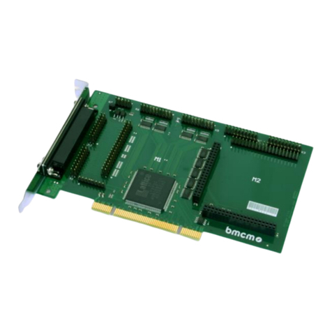
Data Acquisition and Processing Card for Mxx Modules
Features Applications
•2 slots for Mxx modules •acquisition of analog signals
=> up to 32 analog channels •analog controls
•FIFO for rapid data acquisition •recording of digital events
•PCI bus compatible (short PCI!) •digital controls
•16 or 32 digital channels
Page 1
BMC Messsysteme GmbH proudly
presents the
... PCI-Multifunction
Measuring Card ...
with a highly integrated and mo-
dular concept at an unbeatable
price which allows the user to
tackle any measuring task by as-
sembling his individual measuring
card. The MAD modules provide
sampling rates of up to
... 333kHz ... .
Depending on the application vari-
ous modules are available for ana-
log in- and outputs with resolutions
of
... 12 or 16 Bit ... .
The measured data can be simulta-
neuosly displayed and stored on the
hard disk. The switch-over from
one measuring range to another can
be defined for each channel and
does not influence the sampling
rate.
... 16 or 32 digital
in-/ outputs respectively
are available on the PCI-BASE
plate. This means that the base
plate, without any analog module is
a digital I/O card itself.
The
... modular concept ...
easily allows for
... 32 analog inputs ...
with resolutions of 12 or 16 Bit. In
order to access the analog inputs
17..32, BMC Messsysteme offers a
PC card cover with a 37-pole Sub-
D socket plus connecting cable.
At present the following analog
input modules are available:
•MAD 12: 100kHz; 12 Bit
•MAD12f: 333kHz: 12 Bit
•MAD16: 100kHz; 16 Bit
These modules freely combine with
each other or the following analog
modules:
•MDA 12: 12 Bit, 2 outputs
•MDA 12-4:12 Bit, 4 outputs
•MDA 16: 16 Bit, 2 outputs
We provide ActiveX controls STR-
PCI for Windows® 95/98/2000/NT
as well as the operator's software
ST-PCI for the display, control and
automation of analog and digital
processes. These are included with
the "Software Collection"-CD.
As the hardware component of the
measuring data acquisition and
analysis system NextView®/NT by
BMC Messsysteme GmbH, the
PCI-BASE50/300 offers superb
performance under Windows®
98/2000 or NT and is available in
the versions Light, Professional or
Client/Server. A demo version is
included.

PCI-BASE50/300
© BMC Messsysteme GmbH Page 2
Installation: Module Slots M1 and M2, Dongle Slot
Dongle Slot:
If using the NextView®/NT software, the included dongle must be plugged in the IC socket U10. The component is an
ESD - be sure to use a conductive pad connected to ground during installation! Be sure to install the dongles-IC cor-
rectly.
NextView®/NT version 3.1 or higher does not need the dongle so that it will not be included any more.
Module Slot - M1
The 37pole Sub-D socket at the PCI-BASE50/300 allows for the con-
nection of the analog in- and outputs of the modules. The pin connec-
tors P1 and P2 can be used for connecting an AAB amplifier box or
current shunts ZUSP1000 internally.
Module Slot - M2
All connections of the second module slot M2 are accessible via the
pin connectors P9 and P10. Channels 1 and 2 of this module slot can
also be accessed by means of the 37pole Sub-D socket at PIN 18 and
19. In this way, two D/A channels for example can be lead out. When
using the ZUKA16 the channels of the slot M2 are lead out via a
37pole Sub-D socket.
Sub-D 37 Pin Connector
PJ1 and PJ2 Pin Connector
PJ9 and PJ10
The figure below shows the pin assignment of the module slots M1 and M2 of the PCI-BASE50/300:
M1 M2

PCI-BASE50/300
© BMC Messsysteme GmbH Page 3
Pin Assignments
Module Slot 1
Sub-D 37, PJ1 andPJ2 Module Slot 2
PJ9 and PJ10
Pinassignm.
Sub-D37 MAD
(se) MAD
(diff) MDA
12/16 MDA
12-4 Pinassignm.
PJ1, PJ2 Pinassignm.
PJ9, PJ10 MAD
(se) MAD
(diff) MDA
12/16 MDA
12-4 Pinas-
signm.
ZUKA16
1IN1 + IN1 AOut1 AOut1 PJ1/1 PJ9/1 IN1 + IN1 AOut1 AOut1 1
2 IN2 + IN2 AOut2 AOut2 PJ1/3 PJ9/3 IN2 + IN2 AOut2 AOut2 2
3IN3 + IN3 -AOut3 PJ1/5 PJ9/5 IN3 + IN3 -AOut3 3
4 IN4 + IN4 - AOut4 PJ1/7 PJ9/7 IN4 + IN4 - AOut4 4
5IN5 + IN5 - - PJ1/9 PJ9/9 IN5 + IN5 - - 5
6 IN6 + IN6 - - PJ1/11 PJ9/11 IN6 + IN6 - - 6
7IN7 + IN7 - - PJ1/13 PJ9/13 IN7 + IN7 - - 7
8 IN8 + IN8 - - PJ1/15 PJ9/15 IN8 + IN8 - - 8
9IN9 - IN1 - - PJ2/1 PJ9/17 IN9 - IN1 - - 9
10 IN10 - IN2 - - PJ2/3 PJ9/19 IN10 - IN2 - - 10
11 IN11 - IN3 - - PJ2/5 PJ10/1 IN11 - IN3 - - 11
12 IN12 - IN4 - - PJ2/7 PJ10/3 IN12 - IN4 - - 12
13 IN13 - IN5 - - PJ2/9 PJ10/5 IN13 - IN5 - - 13
14 IN14 - IN6 - - PJ2/11 PJ10/7 IN14 - IN6 - - 14
15 IN15 - IN7 - - PJ2/13 PJ10/9 IN15 - IN7 - - 15
16 IN16 - IN8 - - PJ2/15 PJ10/11 IN16 - IN8 - - 16
17 - - (GND) (GND) - - - - 17
18 - - (AOut1) (AOut1) - - - - 18
19 - - (AOut2) (AOut2) - - - - 19
20,21 GND -GND GND PJ1/2,4 PJ9/2,4 GND -GNDGND20,21
22,23 GND - - GND PJ1/6,8 PJ9/6,8 GND - - GND 22,23
24..27 GND - - PJ1/10,12,14,
16 PJ9/10,12,...,
18,20 GND - - - 24..29
28..35 GND - - PJ2/2,4,...,14,
16 PJ10/2,4,...,
10,12 GND - - - 30..35
36 - - - (AOut3) - - - - 36
37 - - - (AOut4) - - - - 37
The channels indicated in brackets represent the channels of the second module slot, if plugged.
Digital In- and Outputs
The PCI-BASE50/300 provides two digital channels with 8/16 input
and 8/16 output lines:
•Pin connector P5 => Input channels 1..8 (PCI-BASE50)
or 1..16 (PCI-BASE50/300)
•Pin connector P6 => Output channels 1..8 (PCI-BASE50)
or 1..16 (PCI-BASE50/300)
The direction of the digital interface is fixed.
The digital in-/ outputs are protected by serial resistors only!

PCI-BASE50/300
© BMC Messsysteme GmbH Page 4
The 20pole pin connectors on the plate represent the connections for the digital interfaces and can be lead from the PC
by means of a relevant socket and a ribbon cable (Option ZUKA16). The figure on the right shows the numbering of
the connector (view from top of the plate). The pin assignment can be taken from the following table:
P5 Function
PIN 1...16 Digital inputs D1..D16
PIN 17 GND
PIN 18 - 20 Not assigned
P6 Function
PIN 1 ...16 Digital outputs D1..D16
PIN 17, 18 Vcc (+5V, 100mA) from PC
PIN 19, 20 GND
PIN 17 and 18 provide 5V DC. This output is protected by a fuse (F1, see figure above).
Pin Assignment Sub-D37 when using ZUKA16
The connector of the ribbon cable which is connected to PIN 1 of the Sub-D 37 (line marked in red) must be plugged
on P6, PIN 1. The second connector must be plugged on P5.
Sub-D 37 Function Sub-D 37 Function
PIN 1 D-OUT 1 PIN 11 D-IN 1
PIN 20 D-OUT 2 PIN 30 D-IN 2
PIN 2 D-OUT 3 PIN 12 D-IN 3
PIN 21 D-OUT 4 PIN 31 D-IN 4
PIN 3 D-OUT 5 PIN 13 D-IN 5
PIN 22 D-OUT 6 PIN 32 D-IN 6
PIN 4 D-OUT 7 PIN 14 D-IN 7
PIN 23 D-OUT 8 PIN 33 D-IN 8
PIN 5 D-OUT 9 PIN 15 D-IN 9
PIN 24 D-OUT 10 PIN 34 D-IN 10
PIN 6 D-OUT 11 PIN 16 D-IN 11
PIN 25 D-OUT 12 PIN 35 D-IN 12
PIN 7 D-OUT 13 PIN 17 D-IN 13
PIN 26 D-OUT 14 PIN 36 D-IN 14
PIN 8 D-OUT 15 PIN 18 D-IN 15
PIN 27 D-OUT 16 PIN 37 D-IN 16
PIN 9 +5V PIN 19 GND
PIN 28 +5V
PIN 10 GND
PIN 29 GND
Software Installation
The installation must proceed in the following order:
1. Driver installation
2. Installation of the programming interface (ActiveX Control)
3. Installation of the operator's software (if desired)
Before using the device, the hardware driver must be installed. The device can be programmed under Windows®
95/98/2000 or NT 4.0 by means of programming languages (Visual Basic, Delphi, Visual C++ etc), which are able to
link the ActiveX Controls, using the programming interface STR-PCI.

PCI-BASE50/300
© BMC Messsysteme GmbH Page 5
The operator´s program ST-PCI allows you to utilize the
hardware´s capacity to its full extent. The device driver,
the ActiveX Control STR-PCI and the operator´s pro-
gram ST-PCI is included on the "Software Collection"-
CD which comes with the delivery.
Put the CD in your CD-ROM drive. The CD starter opens
automatically.
For installation of the software or in order to read the
relevant documentation (PDF files), please select the
entry "Products" and then the product group "PCI-
BASE50/300 ActiveX Control and Modules".
Now choose the desired product. For opening manuals or
data sheets, please first install the program Adobe®Ac-
robat Reader. You will find the corresponding link on the
"Welcome" screen of the CD.
1. Driver Installation
The installation depends on the operating system. If using the PCI-BASE50/300 with Windows® 95/98/2000 please
mount the PC card into your PC. When starting the PC the system announces the new hardware. The hardware assis-
tent will guide you step by step through the installation. For detailed information about the installation of the hardware
drivers see the "Driver Installation Manual (PDF)".
On Windows® NT there is no extra hardware installation necessary. Just mount the PCI-BASE50/300 into your com-
puter and install the ActiveX controls.
2. Installation of the ActiveX Controls STR-PCI
To install or upgrade the ActiveX Control please select the entry "PCI-Baes50/300 ActiveX Control" and start the
installation by choosing the option "STR-PCI-Base50 Setup" or "STR-PCI-BASE50/300 Setup".
If you don´t use the auto run function of the "Software Collection"-CD for installation, you can install by opening the
file pci50-actx-us.exe or pci300-actx-us.exe (english setup) in the directory products / pci.
After a short introduction the driver information will be displayed. Then the required files will be copied to your hard
disk and you will be prompted if the installation has been successful. Restart your computer, if necessary.
3. Installation of the Operator's Program ST-PCI
The USB driver and the ActiveX Control STR-PCI must be installed before installing this program!
The program is installed in the same way as the ActiveX Controls, except that you now select "ST-PCI Control Utili-
ty" instead of STR-PCI. If you don´t start the installation from the CD, open the setup program st-pci-install-
1.0.exe in the directory products / pci.
After a short introduction you will be asked to confirm the suggested installation path and group name or enter your
changes. Then the required files will be copied to your hard disk and prompt will show whether the installation has
been successful. Restart your computer if necessary.
Programming
You will find references about programming and programming examples in the entry "STR-PCI Programming E-
xamples", which you can choose to install. For further information about the programming of the PCI-Base50/300
please read the respective PDF file, which will be installed together with the programming examples. If you don´t start
the installation from the CD, open the setup program pcibase-examples.exe in the directory products / pci.

PCI-BASE50/300
© BMC Messsysteme GmbH Page 6
Important Notes for Using the PCI-BASE50/300
•The PCI-BASE50/300 is only suitable for extra-low voltages - please observe the relevant regulations!
•The PCI-BASE50/300 must only be used in closed PC housings (for reasons relating to EMC).
•All accessible pins are electrostatic sensitive devices. Provide for a conductive work place connected to ground.
•For CE reasons use well shielded cables, connect shield at one end only. Close open inputs, if possible. At the
37pole plug the signals are connected, use shielded cables only. For best possible interference suppression connect
shield at one end only. Close open inputs if necessary. ESD voltages at open lines may cause malfunction.
•The PCI-BASE50/300 ground is electrically connected to the chassis of the PC, which is usually also connected to
ground. Be sure to avoid ground loops since they will cause measuring errors!
•For cleaning use water and mild detergent only. The modules are designed to be maintenance-free.
•The device must not be used for safety-relevant tasks. With the use of the product the customer becomes manufac-
turer by law and is therefore fully responsible for the proper installation and use of the product. In the case of im-
proper use and/or unauthorized interference our warranty ceases and any warranty claim is excluded.
•Improper installation of the modules on the PCI-BASE50/300 may damage the modules and/or the PCI-
BASE50/300. When removing the modules use only blunt tools!
•When connecting internal ribbon cables to the PCI-BASE50/300, please observe that the modules are well venti-
lated to prevent excess heating. Also observe the temperature ranges of the PC.
Technical Data PCI-BASE50/300 (typical at 20°C and 5V Supply)
•
••
•Sampling Parameters (in connection with measuring and analysis software NextView®/NT)
PCI-BASE50 PCI-BASE50/300
Max. cumulative sampling rate: 50kHz 330kHz
Digital input channels: 8 x TTL 16 x TTL
Digital output channels: 8 x TTL 16 x TTL
FIFO: 1kByte 4kByte
Frequenzy drift: max. ±50ppm/°C
Memory depth: depending on the RAM or HD space available (up to 4GByte)
Trigger: rising edge, falling edge, window trigger, logical trigger
Prehistory: 0..99%
* The cumulative sampling rate is the total of the individual channel sampling rates (e.g. 5 channels à 10kHz => 50kHz cum. sampling rate).
•
••
•Digital In-/ Outputs
Level / digital IN Ri:CMOS/TTL-level (0 = 0.0V..0.5V; 1 > 2.6V..5.0V) / 1MΩ
Digital IN surge resistant to: 60V DC
Digital OUTRi/ output current:
1kΩ/ 1mA
•
••
•Signal Connection
Analog In-/ Outputs
(of MAD/MDA modules): All channnels are accessible at a 37pole Sub-D socket at the PC-card blende or via pin connectors.
Digital channels: 2x20pole pin connectors on the plate; The digital channels are brought out via the ZUKA16 (option).
•
••
•General Data
Power supply: +5V from PCI-Bus, max. 500mA
Bus connection: PCI-Bus
CE standards: EN50081T1, EN50082T1, EN61010-1
Max. permiss. potentials: 60V DC acc. to VDE, max. 2kV ESD on the lines
Temperature ranges: ambient temp. 0..40°C, working temp. 0..70°C, storage temp. –25..85°C
Relative humidity: 0 – 90% (not condensing)
Size: 178 x 103 x 13,5 mm3
Other:
Accessory (included): product, PC bracket for mounting, "Software Collection" CD with drivers and documentation, description
Other accessory: connecting cable with bracket for internal cabling ZUKA16, 37-pole Sub-D plug ZUST37, connecting
cables ZUKA37SB, ZUKA37SS, connector box ZU37BNC, current shunts ZUSP1000, modules of the
series MAD/MDA, fuse ZU-SI500
Guarantee: 2 years with effect from sales date, damages at product resulting from improper use excluded
•
••
•Software
Software (included): STR-PCI (ActiveX Control) for programming under Windows® 95/98/2000/NT; operating program ST-
PCI for displaying of analog and digital signals.
NextView®/NT: Measuring and analysis software on Windows®98/2000 or NT 4.0 for the optimum performance of the
measuring card.
Manufacturer: BMC Messsysteme GmbH. Subject to change due to technical improvements. Errors and printing errors exepted. Rev. 6.0 05/25/2001
Table of contents
Other bmcm PCI Card manuals