bmcm USB-AD-OEM User manual

USB-AD-OEM
USB DAQ Device
Really Simple.
Record and output signals with the USB-
AD: The USB data acquisition system is
ideal for universal applications in
measurement and control technology.
Implement your own ideas – just plug in
and head off!
OEM. Compact. Powerful.
Budget Price.
The idea behind the USB-AD-OEM: measuring
where there is very little space. Mounting holes
like 2,5“ HD/SSD mean, you can mount the
USB-AD-OEMin a PC or any other housing.
16 AIn. 1 AOut. 12 Bit. ±5V.
Voltage signals in the ± 5V range are
connected to 16 analog inputs. The sampling
takes place with 12 bit resolution and up to
160Hz total sampling rate. Analog controls are
possible with the analog 12-bit output in the ±
5V output range.
16 Digital In-/Outputs.
Digital states can be recorded or controlled in
16 digital inputs and outputs. The direction of
the digital lines can be selected in groups of 8.
Plug & Play.
The connection to the PC happens via USB.
That way the USB-AD-OEM uses all USB-
typical features (eg. Plug & Play, Hot-Plug). Up
to 127 devices can be connected and installed
during operation.
Powered by USB.
The device is powered by the USB interface.
This reduces the wiring effort to a minimum.
Open for Windows.
The measurement system receives extensive
support from Windows® 8/10. All software for
installing and programming the USB-AD-OEM
is included free of charge.
NextView®. Try For Free.
The device is supported by NextView®, the
software for measurement data acquisition
and analysis. A fully functional 14-day trial
version is included in the scope of delivery.
This allows the functionality of the USB-AD-
OEM to be tested directly.
Functional Diagram

USB-AD-OEM
Page 2
1 Start-up procedure
All available software and documentation for the USB-AD are located on www.bmcm.de/usb-ad-
oem-en in the tab
Downloads.
1. Step: Installation device driver
Install the latest driver package in order to use the USB measurement device. You
will find the package on www.bmcm.de/usb-ad-oem-en in the tab
Downloads
in the
category
BMCM – Drivers
. Open the manual device drivers on www.bmcm.de/man-
driver for more information.
2. Step: Connect up
Connect the provided USB cable to the device and to a free USB port of the PC.
Then start the plug and play installation. The device gets its power supply through
the USB connection.
3a. Step: Measuring with NextView
To be able to use your measurement system with NextView, you just need to
download and install the latest version of NextView on www.nextview.de/download.
In case you did not buy NextView, request a free of charge trial version when first
starting NextView. Find more information about NextView and its installation on
www.nextview.de or in the manual on www.bmcm.de/man-nextview.
3b. Step: Measuring with API
In case you want to use the measurement device without NextView, you need to
download and install the free of charge programming interface LIBAD4. You can find
this on www.bmcm.de/usb-ad-oem-en in the tab
Downloads
in the category
LIBAD
– Programming Interface (API)
, too. Find more information on www.bmcm.de/libad-
en or directly in the manual www.bmcm.de/man-libad.

USB-AD-OEM
Page 3
1 Getting Started
Please install the drivers package by bmcm first. Then connect the USB cable of the USB-AD-OEM to
a free USB sport of the PC. The power is supplied via the USB connection. Now you can install other
software components if needed.
2 Pin Assignment Analog In/Out
Das USB data acquisition system features 16 analog inputs with a measurement range of +/-5V and
an analog output in the range of +/-5V. Signals are connected via a 40-way pin connector:
The maximum potentials versus ground must not exceed
±
7V. In the event of overload on one channel, all
other channels can also display incorrect values.
AGND and DGND are connected to the mass of the PC.
40way pin
conn.
Assignment
1
AIn 1
3
AIn 2
5
AIn 3
7
AIn 4
9
AIn 5
11
AIn 6
13
AIn 7
15
AIn 8
17
AIn 9
19
AIn 10
21
AIn 11
23
AIn 12
25
AIn 13
27
AIn 14
29
AIn 15
31
AIn 16
35
AOut 1
37
-
2 .. 40
AGND
AOut 1

USB-AD-OEM
Page 4
2 Pin Assignement Digital I/O & USB
16 digital Lines can be used as digital in- and outputs (low: 0V..0,7V; high: 3V..5V). The switch over
happens in groups of 8. The auxiliary voltage is available at pin 17 and 18. Signals are connected via
a 40-way pin connector:
40way pin
conn.
Assignment
1
B1
2
B2
3
B3
4
B4
5
B5
6
B6
7
B7
8
B8
9
A1
10
A2
11
A3
12
A4
13
A5
14
A6
15
A7
16
A8
17
Vext
18
Vext
19
DGND
20
DGND
21 ... 31
--
32
Vusb
33
--
34
D-
35
--
36
D+
37
--
38
DGND
39, 40
--
• The lines B1 .. B8 are set as output and A1 .. A8 as input in the default state.
• The digital in- and outputs are protected with 33
W
resistors. An input voltage outside the permitted voltage
range of 0V..5V may damage the device.
• • The connections Vext provide an auxiliary voltage in the range of 4..5V. This is protected by a fuse (10mA).
• • A cable available from a computer retailer can be used to connect the USB line. Please check that the
assignment is correct..
B1
B3
B5
B7
A1
A3
A5
A7
Vext
DGND
--
--
--
--
--
--
--
--
--
--
B2
B4
B6
B8
A2
A4
A6
A8
Vext
DGND
--
--
--
--
--
Vusb
D-
D+
DGND
--

USB-AD-OEM
Page 5
3 Building In and Mechanics
The measuring system is supplied as an open circuit board. Please note not to have any electrical
connections to other components such as housing and cables during installation and operation.
The board is equipped with four holes in the corners. It can be fastened in a housing via bolts. The
hole spacing corresponds to the position of common HDD / SSD 2.5 “mounting holes (M3).
Connect the pad labeled EARTH to the housing earth (functional earth).
4 Interfacing Examples
4.1 Interfacing Examples for Digital Inputs
The digital lines are wired with a serial resistor of 33Wand a pull-down resistor of 100kW.

USB-AD-OEM
Page 6
4.1.1 Connecting an Optocoupler
Optocouplers provide optimum protection at each input
line. With them, it is possible to connect higher voltages
and to protect the hardware from being destroyed.
In this regard, please also see application examples of
the optocoupler you use.
Optocoupler cards (ID:OR8) featuring 8 inputs are available
at bmcm.
4.1.2 Connecting a Push-Button / Switch
Please make sure to use a push-button with debounce
protection, because otherwise several pulses might be
recorded.
The 3.9kWpull-down resistor is optional in order to
create a defined low signal even with long lines.
4.1.3 Connecting a Voltage Divider
If connecting a DC voltage higher than 5V, a voltage
divider must be used so that 5V at the maximum are
applied at the device input. Exceeding the 5V input
voltage might cause damages to the device.
The relation between the two resistors to be used is
calculated with the following formula:
U/U1= (R1+R2)/R1
Input voltages less than 5V are also sufficient (high ³3V).

USB-AD-OEM
Page 7
4.2 Anschaltbeispiele für digitale Ausgänge
The digital lines are wired with a serial resistor of 33Wand a pull-down resistor of 100kW.
4.2.1 Connecting an LED
Only so-called low-current LEDs can be used, because
they already work with 1mA current.
When using standard LEDs, the dropping resistor has to
be adjusted accordingly.
Please also observe the total current listed in the
technical data (see chapter 3).
4.2.2 Connecting a Relay
A connected relay is ideal to switch higher currents.
Since the field coil of the relay requires a higher current
than provided by the measurement system at one line, a
transistor is connected ahead.
Relay cards featuring 8 outputs are available at bmcm.
4.2.3 Connecting a Lamp
A transistor can be used to switch higher loads. The
selected transistor must comply with the maximum
switchable current.
The figure on the right shows an application with a
maximum current of 100mA.

USB-AD-OEM
Page 8
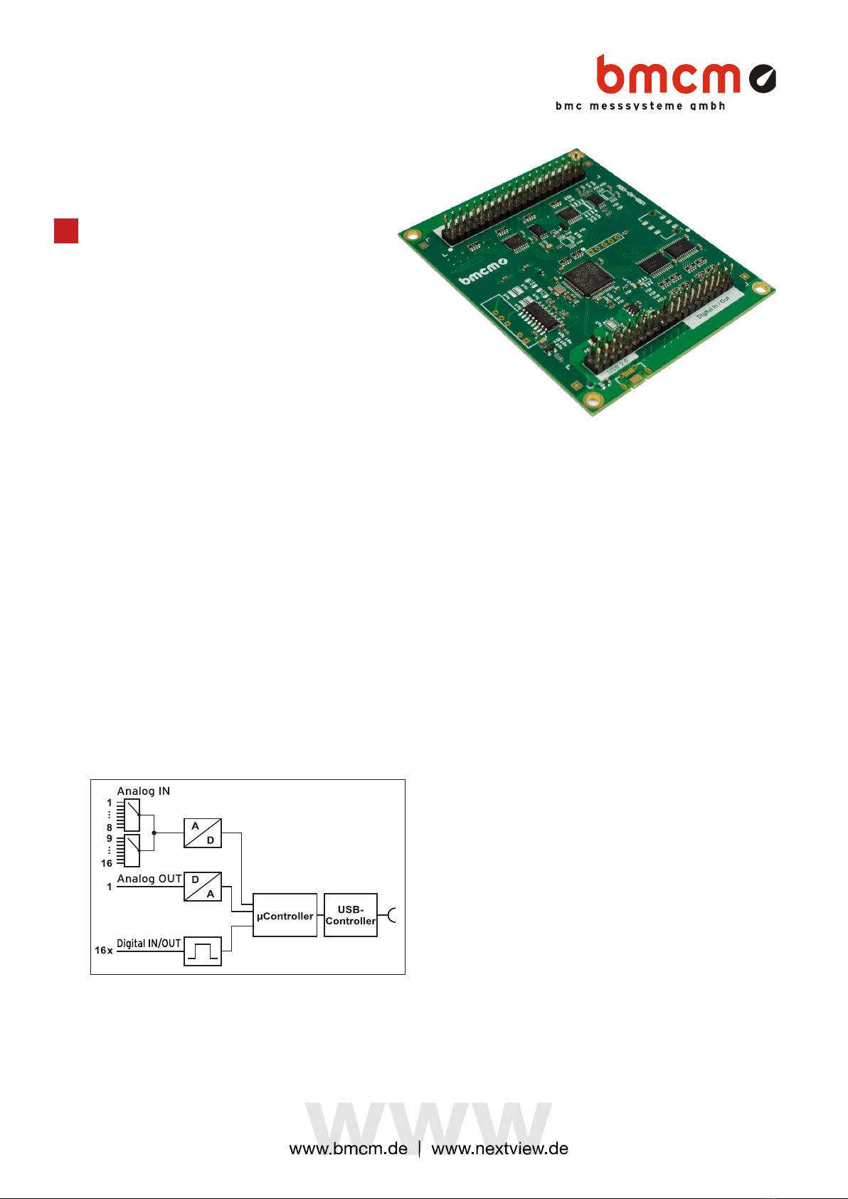
5 Important Notes for Using the USB-AD-OEM
• The device is only suitable for extra-low voltages – please observe the relevant regulations! Only
use the device with housing closed. ESD voltages at open lines may cause malfunction.
• Only use non-solvent detergents for cleaning. The product is designed to be maintenance-free.
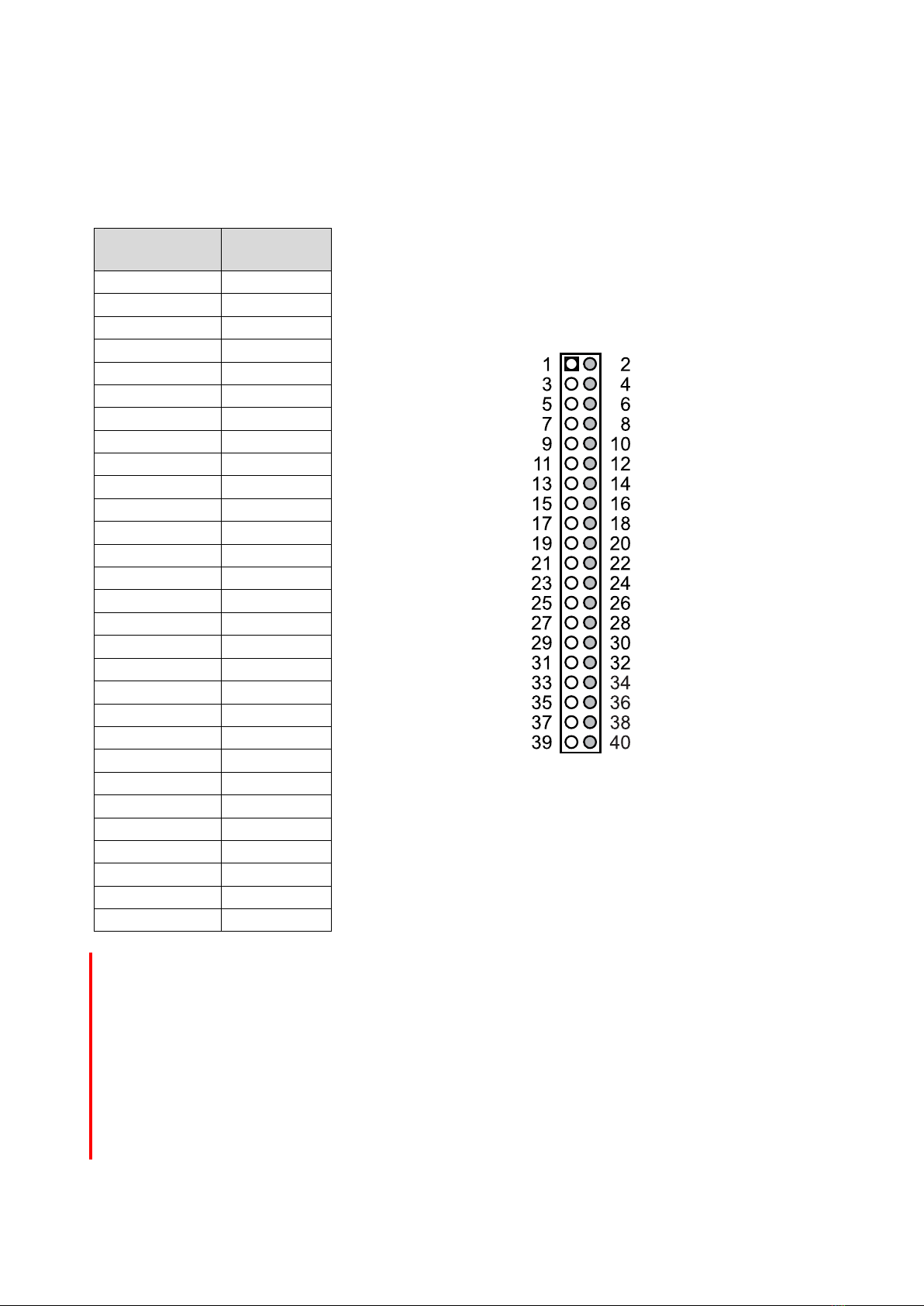
• Signal cables are connected at the 40-way pin connector – preferably use shielded cables. For
best possible interference suppression, connect shield at one end only. Close open inputs if
necessary.
• Connect the earth of the board with the functional earth. Be sure to avoid ground loops since they
will cause measuring errors!
• PCs (notebooks) which are not grounded often produce high potentials to earth at the USB socket
so that safe operation cannot be guaranteed. Connect the measuring system to earth in this case.
• The gain is adjusted to even values. Therefore, only 4000 values (for 12 bit) of the full range of the
converter are used. As a result, the measuring ranges are slightly larger (e.g. ±5.12V) than the
indicated measuring ranges so that overranges can be recognized. The AD converter of the USB-
AD-OEM has a code noise of up to ±1 LSB
• The device must not be used for safety-relevant tasks. With the use of the product, the customer
becomes manufacturer by law and is therefore fully responsible for the proper installation and use
of the product. In the case of improper use and/or unauthorized interference, our warranty ceases
and any warranty claim is excluded.
Do not dispose of the product in the domestic waste or at any waste collection places. It has to be
either duly disposed according to the WEEE directive or can be returned to bmcm at your own
expense.
3 Technical Data (typical at 20°C, after 5min., +5V supply)
• Analog Inputs
Channels // Sampling rate
16 single-ended // up to 10 values/second per channel can be sampled (depending on software and PC)
Surge protection:
max. ±12V (when turned on), max. ±7V (when turned off), max. ±20mA in total of all input channels!
Input resistance // Input capacity:
1MW(with PC turned off: 1kW) // 5pF
Zero shift // Gain drop:
±50ppm/°C // ±50ppm/°C
Measurement range
Resolution
abs. accuracy
typ. noise
Accuracy:
±5V
12 Bit (2,5mV)
±5mV
±1 LSB
The values for accuracy always relate to the respective measuring range. Errors might add at worst.
• Analog Output
Voltage range // Output current:
1 voltage output with ±5V // 1mA max.
Resolution // Accuracy:
12 bit // typ. ±4 LSB, max. ±20 LSB
Zero shift // Gain drop:
±50ppm/°C // ±50ppm/°C
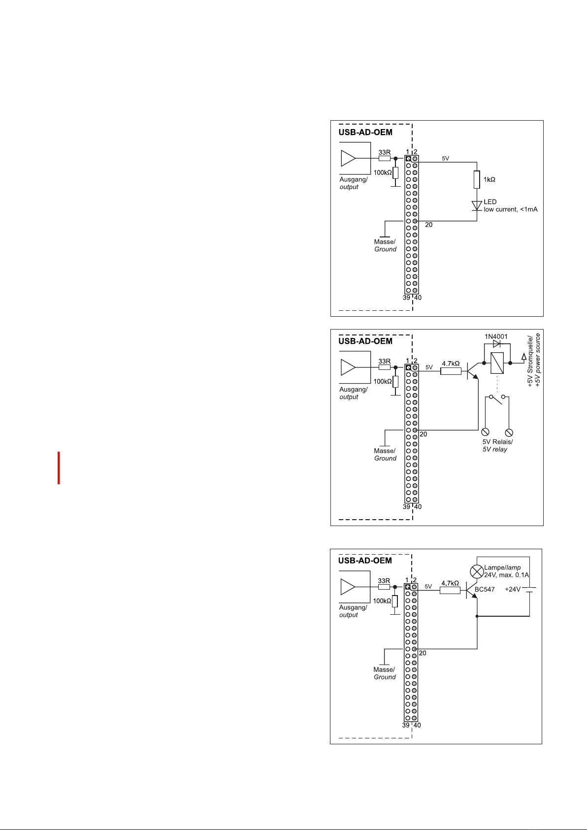
• Digital Inputs/Outputs
Channels // Level:
16 digital lines // CMOS/TTL compatible (low: 0V..0.7V; high: 3V..5V)
Input resistance:
min. 1MW(with PC turned off: 1kW)
Current pick-up per output pin:
25 mA per pin; 50 mA per pin
Surge protection:
max. ±5.5V, protected with 33W
• General Data
Power supply:
+4.5V..+5.5V from USB connection to the PC, max. 100mA
USB interface:
USB 2.0 compatible (full speed)
Connections (analog + digital):
2x40way pin connectors (RM2,54)
CE standards:
EN61000-6-1, EN61000-6-3, EN61010-1; for decl. of conformity (PDF) visit www.bmcm.de
ElektroG // ear registration:
RoHS and WEEE compliant // WEEE Reg.-No. DE75472248
Max. permissible potentials:
60V DC acc. to VDE
, max. 1kV ESD on open lines
Temperature ranges:
-25°C..+70°C
Relative humidity:
0-90% (not condensing)
Dimensions:
83 x 68x x13 mm3
Delivery:
circuit board
Available accessories (optional):
USB cable
Warranty:
2 years from date of purchase at bmcm, claims for damages resulting from improper use excluded
• Software
Software free of charge download:
LIBAD4 SDK for C/C++ programming on Windows® 8/10;
trial version of the measuring software NextView® to test and operate the hardware
NextView (optional):
professional software (versions: Professional, Lite) for the acquisition and analysis of measurement data on
Windows®8/10
Manufacturer: BMC Messsysteme GmbH. Subject to change due to technical improvements. Errors and printing errors excepted. Rev. 1.1
04/29/2020
Table of contents
Other bmcm PCI Card manuals
Popular PCI Card manuals by other brands

Asus
Asus NX1001 Quick installation guide

Ratoc Systems
Ratoc Systems WLTL19105.1 user guide

Kaya Instruments
Kaya Instruments Komodo KY-FGK Hardware Reference and Installation Guide

ICP
ICP ISO-P32C32 user manual

Lattice Semiconductor
Lattice Semiconductor LatticeECP3 Versa user guide

Buffalo
Buffalo WLI2-PCI-G54 Quick setup guide