bmcm USB-PIO-OEM 38 User manual

USB-PIO-OEM
Digital I/O Interface (USB)
Function diagram
24 Channels. Digital.
Signal Output & Monitoring.
Record and output digital signals. The
USB-PIO-OEM features three 8-bit bidirectional
ports. The port lines are led through to the
module pins.
OEM. Simply Integrate.
The module is an OEM version of the USB-PIO
of bmcm to equip your device with a modern and
powerful USB interface. Special emphasis was
put on the easy implementation of both hardware
and software components.
Extra Small. Extra Low-Priced.
In size and construction type, the USB-PIO-OEM
module looks like a 40-pin DIL IC and can easily
be integrated in other devices. Not only the size is
extra small but also the price.
Plug & Play.
The connection to the PC is realized via USB.
The USB-PIO-OEM provides all typical USB
features (e.g. Plug&Play, Hot-Plug). Up to 127
devices can be connected and installed during
operation.
Powered by USB.
The device is supplied with power via the USB
interface. This reduces cabling efforts to a
minimum and makes mobile measurements a lot
easier.
Open for Everyone.
Widely supported: The USB-PIO-OEM can be
used under Windows® XP/7/8/10 as well as under
MAC OS X, Free BSD, and Linux. The OEM
module is 100% software compatible to the USB-
PIO. The complete software for installation and
programming of the device is included for free.
NextView®4. Try for Free.
The module is supported by NextView® 4, the
software for data acquisition and analysis. A fully
functional 30-day trial is included with delivery
to directly test the functionality of the
USB-PIO-OEM.
Accessory. Just Makes it Easier.
For testing purposes or to make your own
developments easier, the test tool
USB-PIO-OEM-TL is available. It provides
standard connectors for the digital lines and the
USB bus. In addition, 24 LEDs allow immediate
status control of the individual I/O pins.

USB-PIO-OEM
Page 2
1 Board View and Pin Assignment
The USB-PIO-OEM features a µ-controller providing 24 digital channels with TTL/CMOS level (low:
0V..1V; high: 3.0V..5V) designed as three 8-bit digital ports A, B, C. The lines are bidirectional. The
direction is set to input or output in groups of 8 (port C: 4) via software.
The connections to the digital interfaces are accessible at the pins of the USB-PIO-OEM. The pin assignment
of the USB-PIO-OEM is listed in the following table.
Pin Assignment (Port / Bit)
38 A/0 30 C/0
37 A/1 29 C/1
36 A/2 28 C/2
35 A/3 27 C/3
34 A/4 11 C/4
33 A/5 12 C/5
32 A/6 13 C/6
31 A/7 14 C/7
3 B/0 19, 20 digital ground (DGND)
4 B/1 40 D+
5 B/2 1 D-
6 B/3 39 VUSB+
7 B/4 2 VUSB-
8 B/5 21 Vcc (VUSB Out, max. 50mA)
9 B/6 22, 23, 24, 25 internal
10 B/7 15, 16, 17, 18, 26 n. c.
Do not apply voltage to the ports without the relevant protective circuit. Two outputs connected
with each other may get damaged by the high flow of current.
The digital inputs are equipped with an internal 100k pull-down resistor for open inputs to be
constantly low.
Pin 22-25 are internally connected. Do not connect anything to these pins!

USB-PIO-OEM
Page 3
2 Interfacing Examples
2.1 Connect Input Signal
Exemplarily, the connection of an input signal at pin 3 and 10 of the USB-PIO-OEM is illustrated. The 1k
resistor and the 100pF capacitor have protective and noise suppressive functions. For voltages higher than
5V a voltage divider is required (see calculation below chapter 2.3).
2.2 Connect LED, Relay to Digital Output
In the figure displayed above, pin 27 and 38 are set to output. At pin 27, the connection of an LED is shown.
At pin 38, a relay is controlled via a transistor.
Please also observe the total current listed in the technical data (see chapter 6).
2.3 Use Voltage Divider
If connecting a DC voltage higher than 5V, a voltage divider must be used so that 5V at the maximum are
applied at the device input. Exceeding the 5V input voltage might cause damages to the device. Due to
TTL/CMOS technology used, input voltages less than 5V are also sufficient (high 3V).
The relation of the resistors to be used can be calculated with the following formula:
U/U1= (R1+R2)/R1

USB-PIO-OEM
Page 4
3 Software Installation
All software and documentation available for the USB-PIO-OEM (installed as "USB-PIO") are
integrated on the "Software Collection" CD included with delivery. When inserting the CD, a CD
starter opens automatically (otherwise: start openhtml.exe).
USB-PIO
Change to the product page of the USB-PIO by selecting the entry "Products" in the CD starter
and then the hardware ("USB-PIO") listed under the interface "USB".
For detailed information about installing or operating the software, please see the corresponding
manuals. The Adobe Acrobat Reader is required to open the documentation in PDF format.
The OEM module is 100% software compatible to the standard version USB-PIO!
You can run the installation directly from CD. If your browser prevents this, first save
the setup program to hard disc before running it separately.
Software Software product Notes Documentation
Device
driver
BMCM-DR
(driver package)
1. install driver package to hard disc
2. Windows® Plug&Play installation
IG-BMCM-DR
(driver installation manual)
Program-
ming
STR-LIBADX ActiveX control for hardware independent
programming
IG-LIBADX
(installation / programming manual)
STR-LIBADX-EX example programs for LIBADX ActiveX control -
SDK-LIBAD SDK with example programs for C/C++ on
Windows®, MAC OS X, FreeBSD, Linux
UM-LIBAD4
(installation / programming manual)
Operating
program
NV4.6 measuring software NextView®4 available in the
Standalone versions:
Lite: "slim" version with basic functions
Pro: full version with complete functional
range
Analysis: version for the analysis of stored
measuring data
NextView®4 can be used for free as a fully
functional 30-day trial version. After purchasing
the software, all projects, measurement files, and
settings can still be used.
DS-NV4
(data sheet)
UM-NV4
(user manual)
"First steps" in the NextView®4
demo project (displayed when first
starting the software)
3.1 Driver Installation
Under Windows®, the driver installation is always required for the USB-PIO-OEM (installed as
"USB-PIO"). Only then additional software can be installed. To make sure the installation is done
correctly, please follow the instructions in the order as described below.
Under MAC OS X, FreeBSD and Linux, driver installation is not necessary.
3.1.1 Install Driver Package
The prior installation of the bmcm driver package BMCM-DR to the hard disc of your PC makes the driver
search for Windows® much easier. Especially in case of driver updates, only the new driver package has to
be installed, the hardware automatically uses the new version.
The link to install the driver package is located on the USB-PIO product page of the "Software Collection"
CD.

USB-PIO-OEM
Page 5
3.1.2 Plug&Play Installation
As soon as the USB-PIO-OEM is connected to the PC, the new hardware will be announced. Since the driver
package has been copied to hard disc before, the hardware will be installed automatically under Windows®
7/8/10. Under Windows® XP, the automatic hardware detection is started by selecting the following:
- Windows® 7/8/10: no specifications required
- Windows® XP: "Install the software automatically" (SP2: do not connect with Windows® Update!)
3.1.3 Check Installation
The entry "Data Acquisition (BMC Messsysteme GmbH)" is included in the Windows® Device Manager
after successful installation displaying the installed bmcm hardware. To open the Device Manager, proceed
as follows:
- Windows® 7: Start / Control Panel / System and Security / System / Device Manager
- Windows® 8/10: Right-click screen corner bottom left (keyboard "Windows+X") / Device Manager
- Windows® XP: Start / Control Panel / System / TAB "Hardware" / button "Device Manager"
Double click the USB-PIO to show its properties. For general information, any existing device conflicts, and
possible sources of error, see TAB "General".
3.2 Programming
Programming the USB-PIO-OEM with Visual Basic®, Delphi®, Visual C++ under Windows® XP/7/8/10 is
possible with the hardware independent STR-LIBADX. It is available on the USB-PIO-OEM product page
of the "Software Collection" CD. After installation, the ActiveX control must be loaded into the respective
programming environment.
- Visual Basic®: menu "Project / Components", entry "LIBADX Object Library 4.0"
- Delphi®: menu "Components / Import ActiveX", entry "LIBADX Object Library 4.0"
If you select the entry STR-LIBADX-EX listed directly under the installation program of the corresponding
ActiveX control, you can install example programs (with source code) demonstrating how to apply the
ActiveX control.
Programming the USB-PIO (installed as "USB-PIO") under Mac OS X and Unix (FreeBSD,
Linux) with C/C++ is done by means of the LIBAD4 programming interface.
The SDK-LIBAD for the respective operating system (also Windows®) is included on the product
page of the USB-PIO. For further information about how to integrate the SDK in the programming
environment, please see the corresponding programming manual UM-LIBAD4.
3.3 Using USB-PIO-OEM with NextView®4
Install the fully functional trial of the professional software NextView®4 for measurement data acquisition
and processing to directly test the features and functions of the USB-PIO-OEM.
The setup program NV4.6 is available on the product page of the card. When first starting the
software, request a license number with the option "Request 30 days free trial version" being checked
and select your device (USB-PIO) in the following dialog "Device Setup".
The data sheet and the start project of NextView®4 contain first instructions about how to install and operate
the program. For detailed information, an online help is provided.
The trial is valid for 30 days after requesting the license number. If a license is not purchased
within this period, the functional range of NextView®4 will be considerably cut down!

USB-PIO-OEM
Page 6
4 Test Tool USB-PIO-OEM-TL
Figure 1
The test adapter USB-PIO-OEM-TL is provided to directly test the functions of the USB-PIO-OEM. Plug
the OEM module onto the 40-pin socket.
Make sure the orientation of the module is correct (see Figure 1, pin 1 top right) to avoid damages of
the module.
4.1 Digital Inputs and Outputs
The 24 digital lines are led through to the 25-pin D-Sub female
connector (P1, see Figure 1) of the test tool.
The pin assignment of the USB-PIO-OEM as well as of the
D-Sub25 female of the USB-PIO-OEM-TL are listed in the
following table.
Pin
USB-PIO-OEM
Assignment
(Port / Bit)
Pin
(D-Sub25)
Pin
USB-PIO-OEM
Assignment
(Port / Bit)
Pin
(D-Sub25)
38 A/0 1 7 B/4 7
37 A/1 14 8 B/5 20
36 A/2 2 9 B/6 8
35 A/3 15 10 B/7 21
34 A/4 3 30 C/0 9
33 A/5 16 29 C/1 22
32 A/6 4 28 C/2 10
31 A/7 17 27 C/3 23
3 B/0 5 11 C/4 11
4 B/1 18 12 C/5 24
5 B/2 6 13 C/6 12
6 B/3 19 14 C/7 25
19, 20 digital ground (DGND) 13

USB-PIO-OEM
Page 7
Do not apply voltage to the ports without the relevant protective circuit. Two outputs connected
with each other may get damaged by the high flow of current.
The digital inputs are equipped with an internal 100k pull-down resistor for open inputs to be
constantly low.
4.2 USB Connection
Via the USB connector type B (P2, see Figure 1, the test tool and the OEM
module are connected to the USB interface of the PC and also supplied by it
(VUSB = 4..5V, pins 2-3 ("USB PWR") of the 3-pin jumper J1 closed).
4.3 LEDs
If a digital input or output is high, it will be indicated by the relating LED on the USB-PIO-OEM-TL. Open
the 2-pin jumper "LEDs ON" (J2, see Figure 1) on the test tool to disable this function.

USB-PIO-OEM
Page 8
5 Important Notes for Using the USB-PIO-OEM
The device is only suitable for extra-low voltages - please observe the relevant regulations! Only use the device
with housing closed. ESD voltages at open lines may cause malfunction.
Definition and test of the CE-standards to be applied must be made by the operator!
Only use non-solvent detergents for cleaning. The product is designed to be maintenance-free.
Signal cables are connected at the module pins – preferably use shielded cables. For best possible interference
suppression, connect shield at one end only. Close open inputs if necessary.
The device ground and the chassis are electrically connected to the chassis of the PC, which is usually also
connected to ground. Be sure to avoid ground loops since they will cause measuring errors!
PCs (notebooks) which are not grounded often produce high potentials to earth at the USB socket so that safe
operation cannot be guaranteed. In this case, connect the measuring system to earth.
The device must not be used for safety-relevant tasks. With the use of the product, the customer becomes
manufacturer by law and is therefore fully responsible for the proper installation and use of the product. In the case
of improper use and/or unauthorized interference, our warranty ceases and any warranty claim is excluded.
Do not dispose of the product in the domestic waste or at any waste collection places. It has to be either duly
disposed according to the WEEE directive or can be returned to bmcm at your own expense.
6 Technical Data
(typical at 20°C, after 5min., +5V supply)
Digital Inputs/Outputs
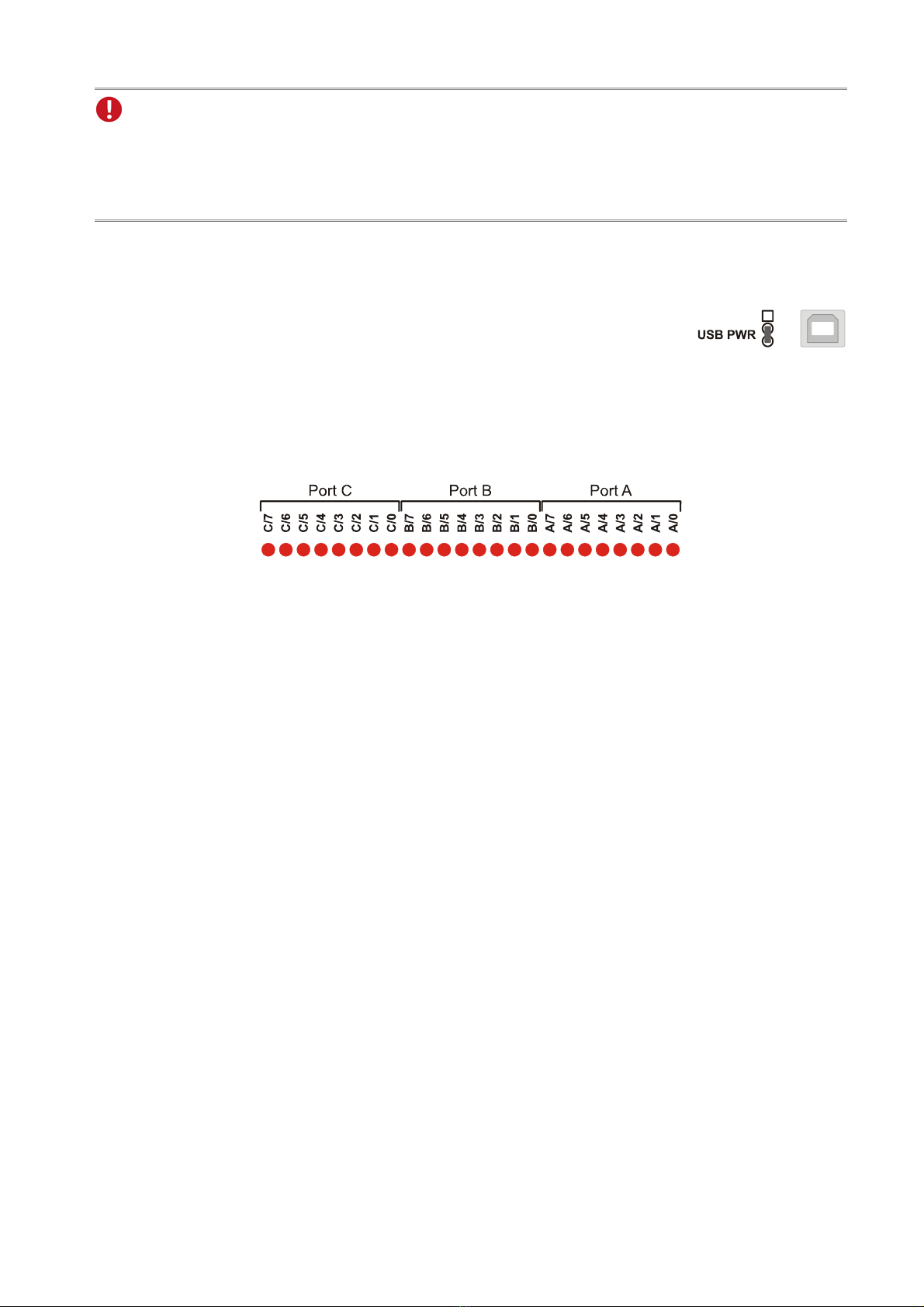
Lines: 3x 8 lines (bidirectional, set in groups of 8, port C in groups of 4)
Level: CMOS/TTL compatible (low: 0V..0.7V; high: 3V..5V)
Current pick-up per output pin: max. 5mA (with app. 4V-level), max. 20mA in total of all output channels!
Sampling rate: up to 500 values/second can be sampled (depending on software and PC)
Input resistance: 100k pull-down resistor (PC off: 1k)
Surge protection: max. 5.5V, max. max. 20mA in total of all channels!
USB interface: USB 2.0 compatible (full-speed)
General Data
Power supply: +4.5V..+5.5V from USB connection to the PC, max. 100mA
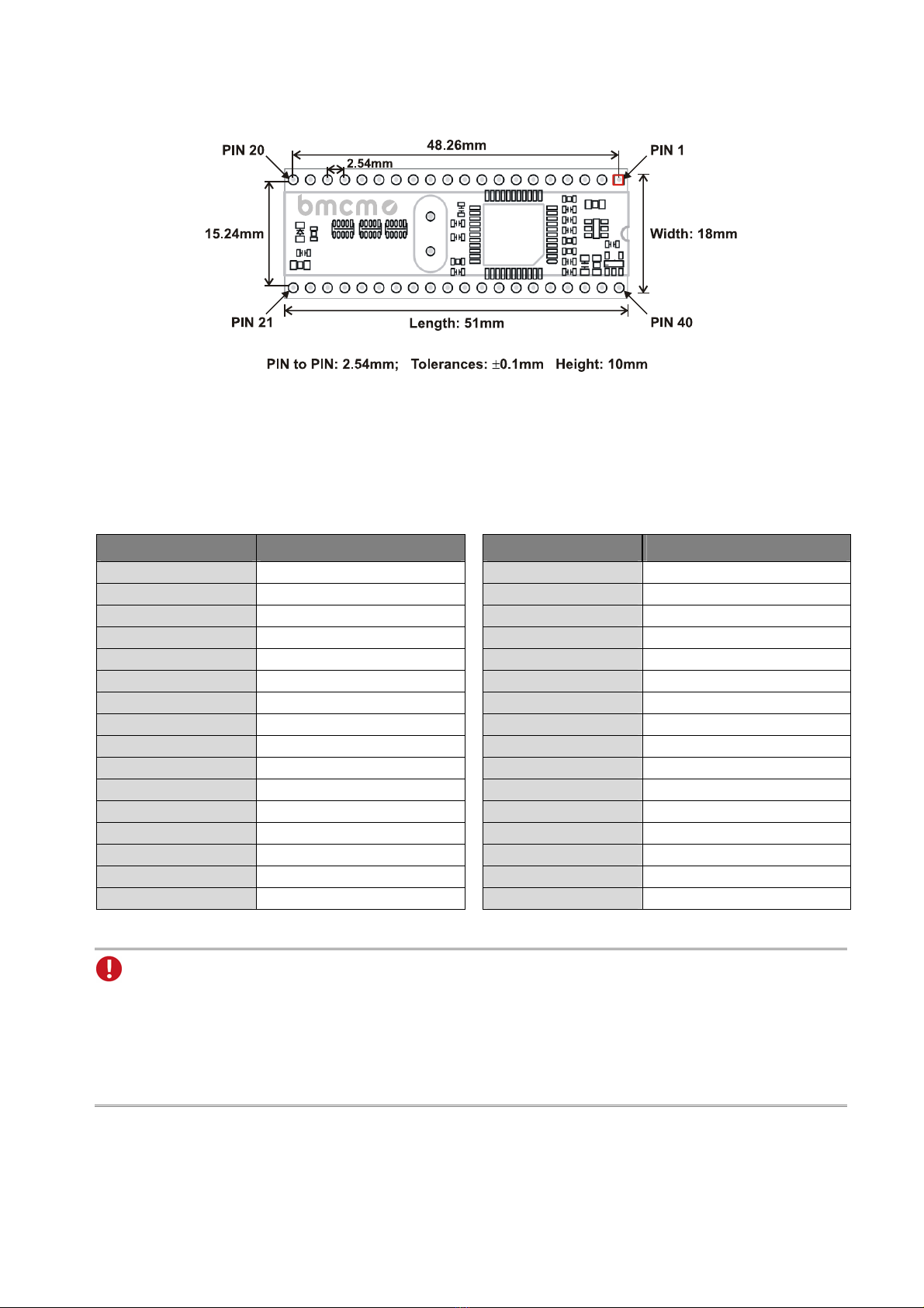
Connections: 40-pin DIL module, connectors with 2.54mm spacing
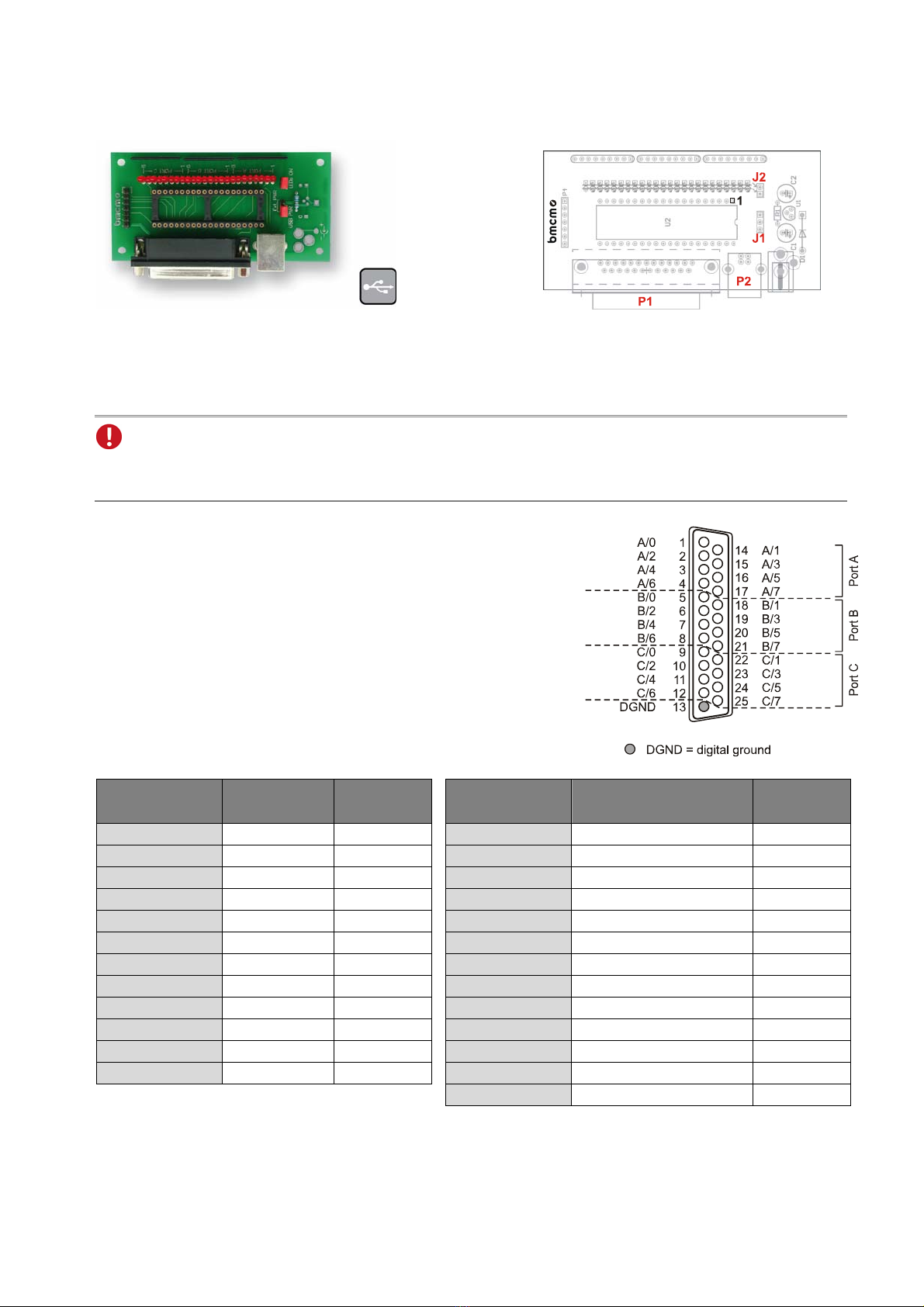
Digital connections: all 24 lines at module pins
CE standards: Definition and test by the operator!!; for decl. of conformity (PDF) visit www.bmcm.de
ElektroG // ear registration: RoHS and WEEE compliant // WEEE Reg.-No. DE75472248
Max. permissible potentials: max. 1kV ESD on open lines
Temperature ranges: operating temp. 0..70C, storage temp. –25..+85°C
Relative humidity: 0-90% (not condensing)
Dimensions: 51 x 18 x 10mm3
Protection type: IP00
Delivery: module, "Software Collection" CD, description
Available accessories (optional): test board USB-PIO-OEM-TL
Warranty: 2 years from date of purchase at bmcm, claims for damages resulting from improper use excluded
Software
Software on CD (included): ActiveX Controls LIBADX (hardware independent) for programming on Windows® XP/7/8/10,
LIBAD4 SDK for C/C++ programming on Windows® XP/7/8/10, Mac OS X, Unix (FreeBSD, Linux);
trial version of the measuring software NextView®4 to test and operate the hardware
NextView®4 (optional): professional software (versions: Professional, Lite) for the acquisition and analysis of measurement
data on Windows® XP/7/8/10
Manufacturer: BMC Messsysteme GmbH. Subject to change due to technical improvements. Errors and printing errors excepted. Rev. 1.0 05/16/2018
Table of contents
Other bmcm Recording Equipment manuals