USB-PIO
Digital I/O Interface (USB)
24 Channels. Digital.
Signal Output & Monitoring.
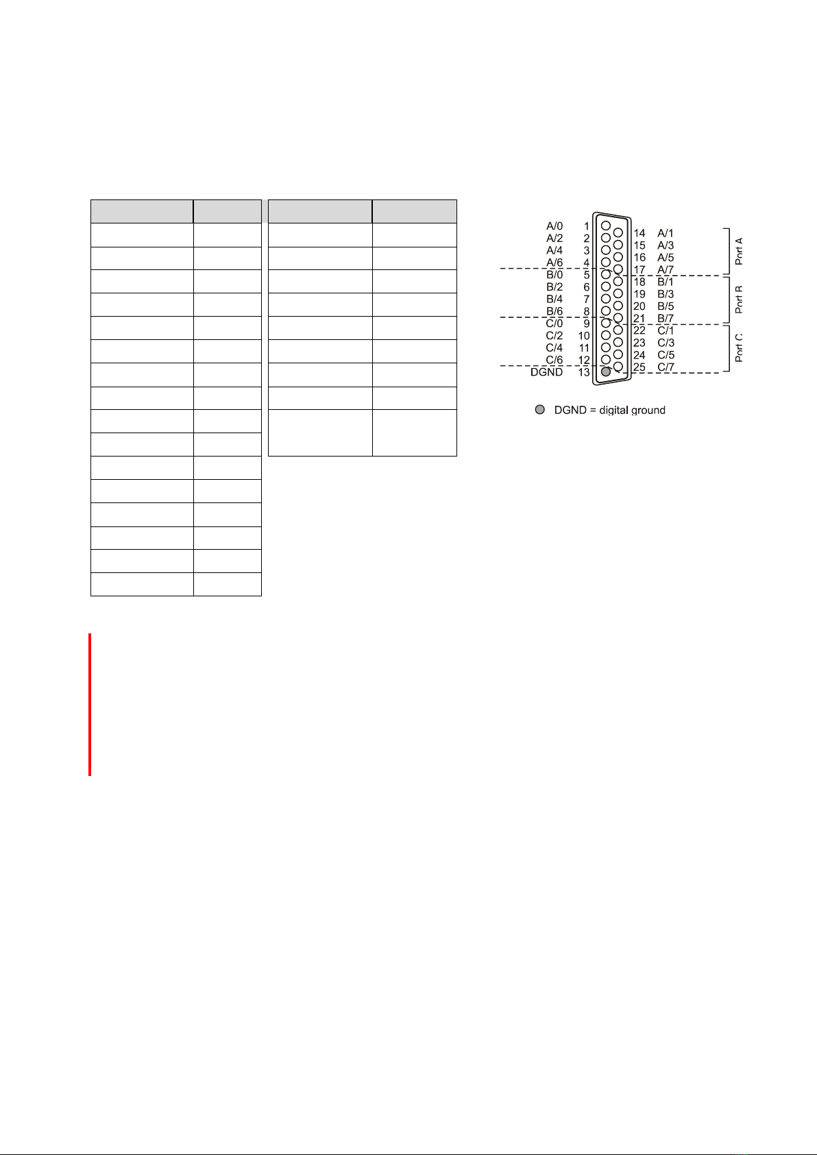
Record and output digital TTL signals. The
USB-PIO features three 8-bit bidirectional
ports. The port lines are led out to a 25-pin D-
Sub female connector.
Extra Small. Extra Red.
Extra Low-Priced.
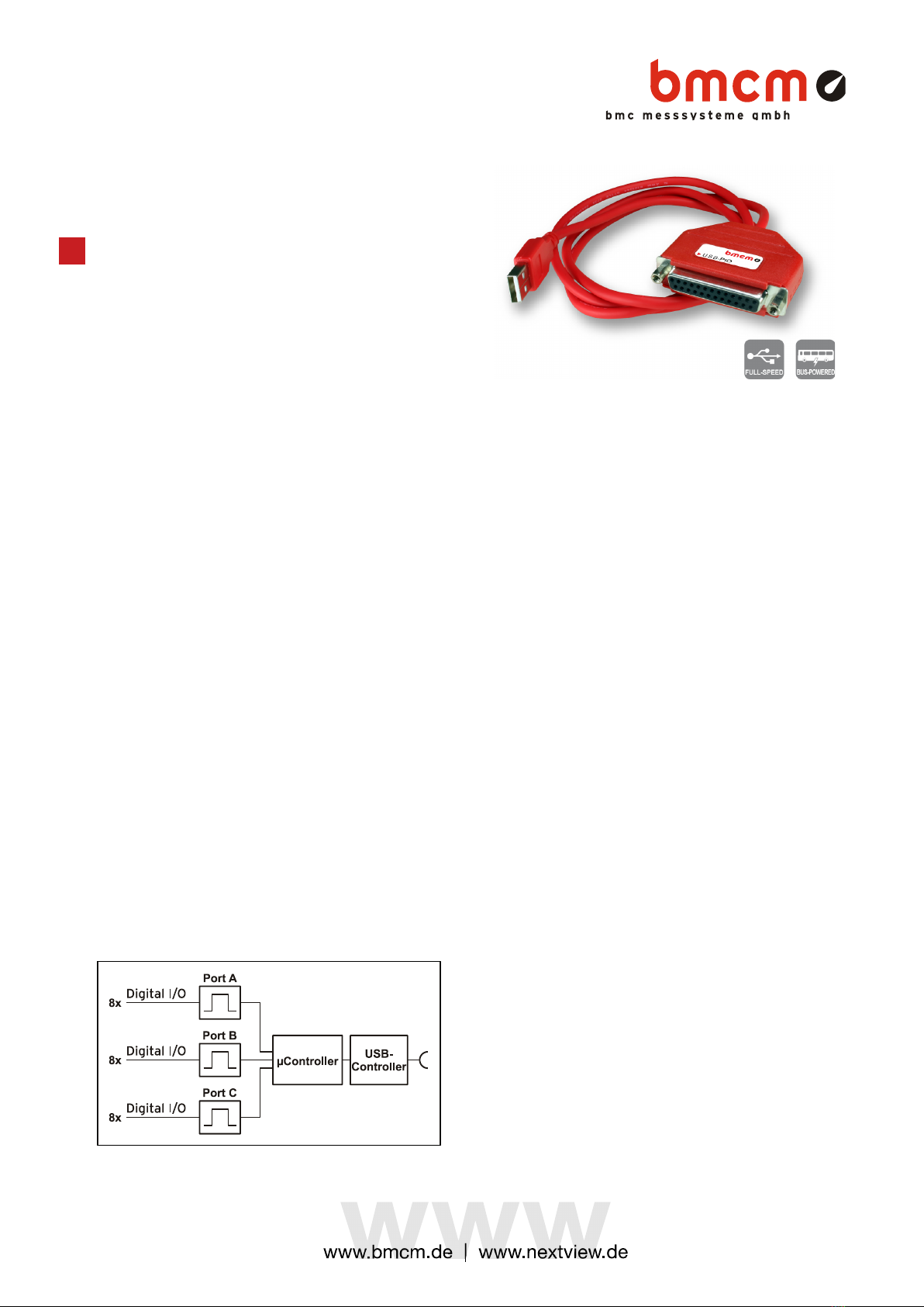
The unique idea of the USB-PIO: the device is
accommodated in the D-Sub connector
housing. Not only the size is extra small but
also the price.
Plug & Play.
The connection to the PC is realized via USB.
The USB-PIO provides all typical USB features
(e.g. Plug&Play, Hot-Plug). Up to 127 devices
can be connected and installed during
operation.
Powered by USB.
The device is supplied with power via the USB
interface. This reduces cabling efforts to a
minimum and makes mobile measurements a
lot easier.
Open for Everyone.
Widely supported: The USB-PIO can be used
under Windows®XP/7/8/10 as well as under
Mac OS X, Free BSD, and Linux. The
complete software for installation and
programming of the device is included for free.
NextView®. Try for Free.
The DAQ system is supported by NextView®,
the software for data acquisition and analysis.
A fully functional 14-day trial is included with
delivery to directly test the functionality of the
USB-PIO.
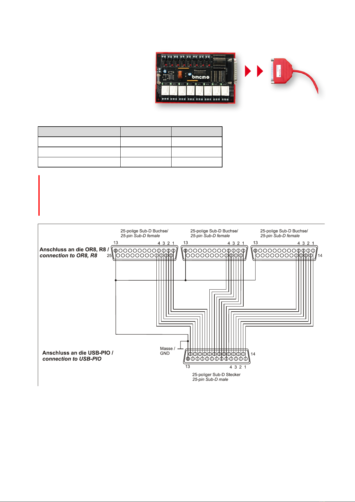
Get Connected.
Various optocoupler and relay cards are
available at bmcm to electrically isolate the
digital lines. For the USB-PIO it is particularly
easy as only a 25-pin D-Sub extension cable
is needed for connecting.
Functional diagram and pin assignment