bmcm USB-PIO-OEM User manual

USB-PIO-OEM
Digital I/O Interface (USB)
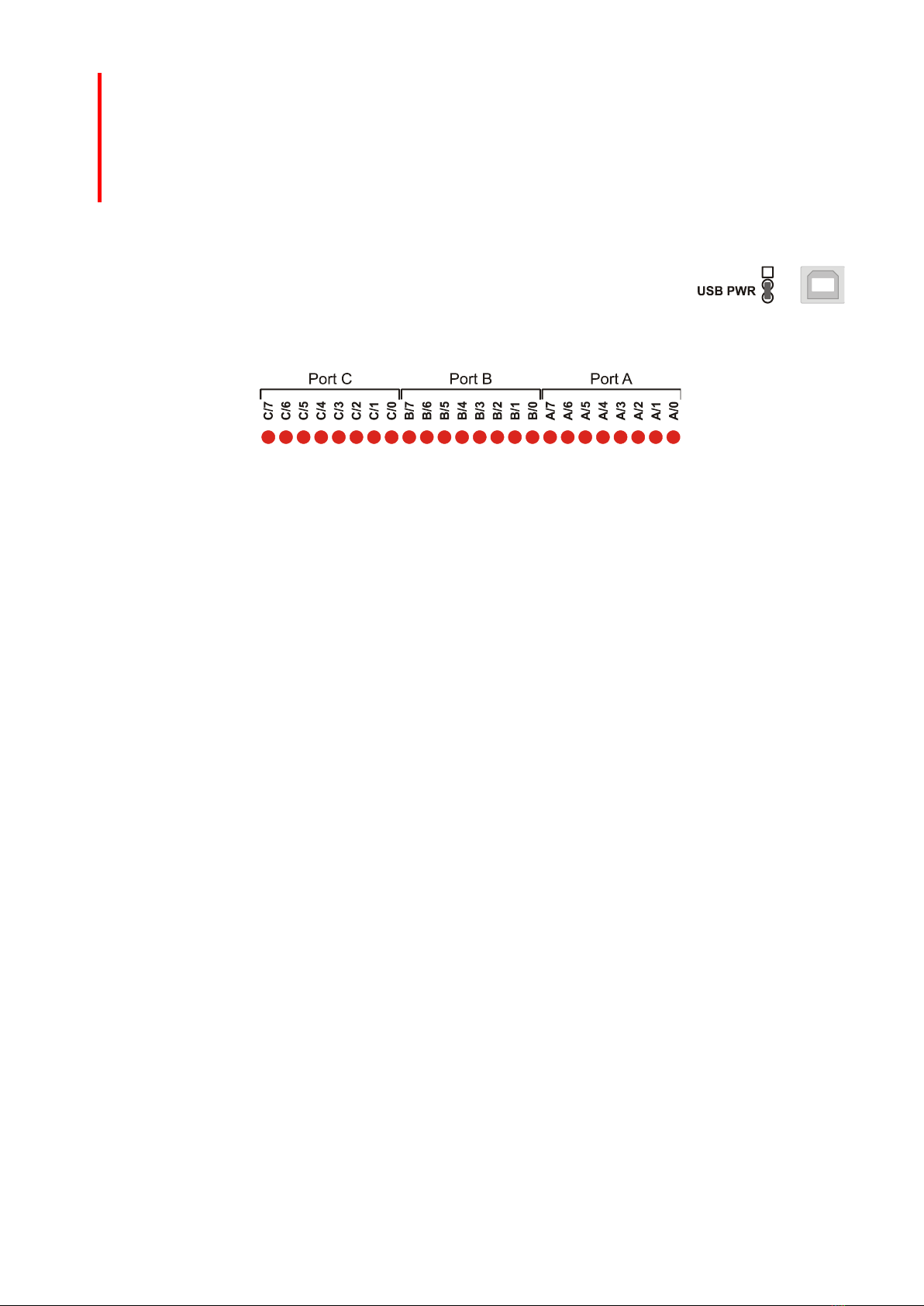
24 Channels. Digital.
Signal Output & Monitoring.
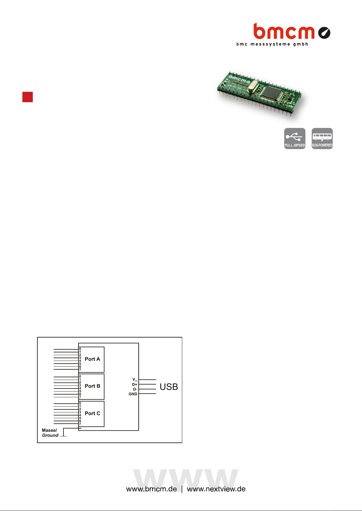
Record and output digital signals. The
USB-PIO-OEM features three 8-bit
bidirectional ports. The port lines are led
through to the module pins.
OEM. Simply Integrate.
The module is an OEM version of the USB-PIO
of bmcm to equip your device with a modern
and powerful USB interface. Special emphasis
was put on the easy implementation of both
hardware and software components.
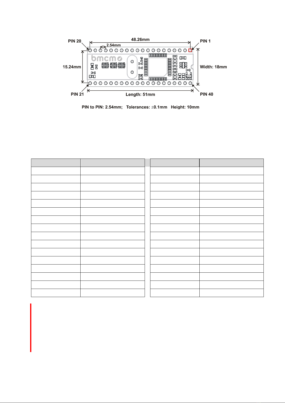
Extra Small. Extra Low-Priced.
In size and construction type, the USB-PIO-
OEM module looks like a 40-pin DIL IC and
can easily be integrated in other devices. Not
only the size is extra small but also the price.
Plug & Play.
The connection to the PC is realized via USB.
The USB-PIO-OEM provides all typical USB
features (e.g. Plug&Play, Hot-Plug). Up to 127
devices can be connected and installed during
operation.
Powered by USB.
The device is supplied with power via the USB
interface. This reduces cabling efforts to a
minimum and makes mobile measurements a
lot easier.
Open for Everyone.
Widely supported: The USB-PIO-OEM can be
used under Windows®XP/7/8/10 as well as
under MAC OS X, Free BSD, and Linux. The
OEM module is 100% software compatible to
the USB-PIO. The complete software for
installation and programming of the device is
included for free.
NextView®. Try for Free.
The module is supported by NextView®, the
software for data acquisition and analysis. A
fully functional 14-day trial is included with
delivery to directly test the functionality of the
USB-PIO-OEM.
Accessory. Just Makes it Easier.
For testing purposes or to make your own
developments easier, the test tool USB-PIO-
OEM-TL is available. It provides standard
connectors for the digital lines and the USB
bus. In addition, 24 LEDs allow immediate
status control of the individual I/O pins.
Function diagram

USB-PIO-OEM
Seite 2
1Start-up procedure
All available software and documentation for the USB-PIO-OEM are located on www.bmcm.de/usb-
pio-oem-en in the tab Downloads.
1. Step: Installation device driver
Install the latest driver package in order to use the USB measurement device. You will
find the package on www.bmcm.de/usb-pio-oem-en in the tab Downloads in the
category BMCM –Drivers. Open the manual device drivers on www.bmcm.de/man-
driver for more information.
2. Step: Connect up
Connect the USB-PIO-OEM with the PC. Then boot the PC and start up the plug and
play installation.
3a. Step: Measuring with NextView
To be able to use your measurement system with NextView, you just need to
download and install the latest version of NextView on www.nextview.de/download. In
case you did not buy NextView, request a free of charge trial version when first
starting NextView. Find more information about NextView and its installation on
www.nextview.de or in the manual on www.bmcm.de/man-nextview.
3b. Step: Measuring with API
In case you want to use the measurement device without NextView, you need to download
and install the free of charge programming interface LIBAD4. You can find this on
www.bmcm.de/usb-pio-oem-en in the tab Downloads in the category LIBAD –Programming
Interface (API), too. Find more information on www.bmcm.de/libad-en or directly in the manual
www.bmcm.de/man-libad.

USB-PIO-OEM
Seite 3
2Board View and Pin Assignment
The USB-PIO-OEM features a µ-controller providing 24 digital channels with TTL/CMOS level (low:
0V..1V; high: 3.0V..5V) designed as three 8-bit digital ports A, B, C. The lines are bidirectional. The
direction is set to input or output in groups of 8 (port C: 4) via software.
The connections to the digital interfaces are accessible at the pins of the USB-PIO-OEM. The pin
assignment of the USB-PIO-OEM is listed in the following table.
Pin
Assignment (Port / Bit)
Pin
Assignment (Port / Bit)
38
A/0
30
C/0
37
A/1
29
C/1
36
A/2
28
C/2
35
A/3
27
C/3
34
A/4
11
C/4
33
A/5
12
C/5
32
A/6
13
C/6
31
A/7
14
C/7
3
B/0
19, 20
digital ground (DGND)
4
B/1
40
D+
5
B/2
1
D-
6
B/3
39
VUSB+
7
B/4
2
VUSB-
8
B/5
21
Vcc (VUSB Out, max. 50mA)
9
B/6
22, 23, 24, 25
internal
10
B/7
15, 16, 17, 18, 26
n. c.
•Do not apply voltage to the ports without the relevant protective circuit. Two outputs connected
with each other may get damaged by the high flow of current.
•The digital inputs are equipped with an internal 100kpull-down resistor for open inputs to be
constantly low.
•Pin 22-25 are internally connected. Do not connect anything to these pins!

USB-PIO-OEM
Seite 4
1Interfacing Examples
1.1 Connect Input Signal
Exemplarily, the connection of an input signal at pin 3 and 10 of the USB-PIO-OEM is illustrated. The
1kresistor and the 100pF capacitor have protective and noise suppressive functions. For voltages
higher than 5V a voltage divider is required (see calculation below chapter 1.3).
1.2 Connect LED, Relay to Digital Output
In the figure displayed above, pin 27 and 38 are set to output. At pin 27, the connection of an LED is
shown. At pin 38, a relay is controlled via a transistor.
Please also observe the total current listed in the technical data (see chapter 0).
1.3 Use Voltage Divider
If connecting a DC voltage higher than 5V, a voltage divider must be used so that 5V at the maximum
are applied at the device input. Exceeding the 5V input voltage might cause damages to the device.
Due to TTL/CMOS technology used, input voltages less than 5V are also sufficient (high 3V).
The relation of the resistors to be used can be calculated with the following formula:
U/U1= (R1+R2)/R1

USB-PIO-OEM
Seite 5
2Test Tool USB-PIO-OEM-TL
Figure 1
The test adapter USB-PIO-OEM-TL is provided to directly test the functions of the USB-PIO-OEM.
Plug the OEM module onto the 40-pin socket.
Make sure the orientation of the module is correct (see Figure 1, pin 1 top right) to avoid damages of
the module.
2.1 Digital Inputs and Outputs
The 24 digital lines are led through to the 25-pin D-Sub
female connector (P1, see Figure 1) of the test tool.
The pin assignment of the USB-PIO-OEM as well as of the
D-Sub25 female of the USB-PIO-OEM-TL are listed in the
following table.
Pin
USB-PIO-OEM
Assignment
(Port / Bit)
Pin
(D-Sub25)
Pin
USB-PIO-OEM
Assignment
(Port / Bit)
Pin
(D-Sub25)
38
A/0
1
7
B/4
7
37
A/1
14
8
B/5
20
36
A/2
2
9
B/6
8
35
A/3
15
10
B/7
21
34
A/4
3
30
C/0
9
33
A/5
16
29
C/1
22
32
A/6
4
28
C/2
10
31
A/7
17
27
C/3
23
3
B/0
5
11
C/4
11
4
B/1
18
12
C/5
24
5
B/2
6
13
C/6
12
6
B/3
19
14
C/7
25
19, 20
digital ground (DGND)
13

USB-PIO-OEM
Seite 6
•Do not apply voltage to the ports without the relevant protective circuit. Two outputs connected
with each other may get damaged by the high flow of current.
•The digital inputs are equipped with an internal 100kpull-down resistor for open inputs to be
constantly low.
2.2 USB Connection
Via the USB connector type B (P2, see Figure 1, the test tool and the OEM
module are connected to the USB interface of the PC and also supplied by it
(VUSB = 4..5V, pins 2-3 ("USB PWR") of the 3-pin jumper J1 closed).
2.3 LEDs
If a digital input or output is high, it will be indicated by the relating LED on the USB-PIO-OEM-TL.
Open the 2-pin jumper "LEDs ON" (J2, see Figure 1) on the test tool to disable this function.

USB-PIO-OEM
Seite 7
3Important Notes for Using the USB-PIO-OEM
•The device is only suitable for extra-low voltages - please observe the relevant regulations! Only use the
device with housing closed. ESD voltages at open lines may cause malfunction.
•Definition and test of the CE-standards to be applied must be made by the operator!
•Only use non-solvent detergents for cleaning. The product is designed to be maintenance-free.
•Signal cables are connected at the module pins –preferably use shielded cables. For best possible
interference suppression, connect shield at one end only. Close open inputs if necessary.
•The device ground and the chassis are electrically connected to the chassis of the PC, which is usually also
connected to ground. Be sure to avoid ground loops since they will cause measuring errors!
•PCs (notebooks) which are not grounded often produce high potentials to earth at the USB socket so that
safe operation cannot be guaranteed. In this case, connect the measuring system to earth.
•The device must not be used for safety-relevant tasks. With the use of the product, the customer becomes
manufacturer by law and is therefore fully responsible for the proper installation and use of the product. In the
case of improper use and/or unauthorized interference, our warranty ceases and any warranty claim is
excluded.
Do not dispose of the product in the domestic waste or at any waste collection places. It has to be either duly
disposed according to the WEEE directive or can be returned to bmcm at your own expense.

USB-PIO-OEM
Seite 8
4Technical Data
(typical at 20°C, after 5min., +5V supply)
•Digital Inputs/Outputs
Lines:
3x 8 lines (bidirectional, set in groups of 8, port C in groups of 4)
Level:
CMOS/TTL compatible (low: 0V..0.7V; high: 3V..5V)
Current pick-up per output pin:
max. 5mA (with app. 4V-level), max. 20mA in total of all output channels!
Sampling rate:
up to 500 values/second can be sampled (depending on software and PC)
Input resistance:
100kpull-down resistor (PC off: 1k)
Surge protection:
max. 5.5V, max. max. 20mA in total of all channels!
USB interface:
USB 2.0 compatible (full-speed)
•General Data
Power supply:
+4.5V..+5.5V from USB connection to the PC, max. 100mA
Connections:
40-pin DIL module, connectors with 2.54mm spacing
Digital connections:
all 24 lines at module pins
CE standards:
Definition and test by the operator!!; for decl. of conformity (PDF) visit www.bmcm.de
ElektroG // ear registration:
RoHS and WEEE compliant // WEEE Reg.-No. DE75472248
Max. permissible potentials:
max. 1kV ESD on open lines
Temperature ranges:
operating temp. 0..70 C, storage temp. –25..+85°C
Relative humidity:
0-90% (not condensing)
Dimensions:
51 x 18 x 10mm3
Protection type:
IP00
Delivery:
module
Available accessories (optional):
test board USB-PIO-OEM-TL
Warranty:
2 years from date of purchase at bmcm, claims for damages resulting from improper use excluded
•Software
Software free of charge download:
LIBAD4 SDK for C/C++ programming on Windows® XP/7/8/10, Mac OS X, Unix (FreeBSD, Linux);
trial version of the measuring software NextView®to test and operate the hardware
NextView®(optional):
professional software (versions: Professional, Lite) for the acquisition and analysis of measurement data on
Windows®8/10
Manufacturer: BMC Messsysteme GmbH. Subject to change due to technical improvements. Errors and printing errors excepted. Rev. 1.1 02/11/2020
Table of contents
Other bmcm Recording Equipment manuals
Popular Recording Equipment manuals by other brands

PS Engineering
PS Engineering PAC15EX System installation and operation manual

Philips
Philips AZ330T user manual

Zoom
Zoom RFX-2000 Operation manual

Gainlab Audio
Gainlab Audio GLA-TC2 Calibration manual

Oakley
Oakley Filtrex II Builder's guide

HMS Networks
HMS Networks Intesis INBACHIT001R000 quick start guide