Bms Bulut Makina TKM-459 Quick start guide

2
1DESCRIPTION OF THE HARDNESS TESTER _________________________________________________3
1.1 Purpose of the Hardness Tester ____________________________________________________________ 3
1.2 Hardness Tester Operating Principle ________________________________________________________ 3
1.3 Hardness Tester Functions ________________________________________________________________ 3
1.4 Technical Characteristics _________________________________________________________________ 4
1.5 Hardness Tester Sensors__________________________________________________________________ 5
1.6 General Information _____________________________________________________________________ 6
1.7 Hardness Tester Menu ___________________________________________________________________ 6
1.8 Settings Entry Mechanism ________________________________________________________________ 6
2OPERATION ________________________________________________________________________7
2.1 Hardness Measurement Procedure _________________________________________________________ 7
2.2 Control and Results Submission in the Course of Measurements _________________________________ 7
2.3 Set up of Averaging Parameters____________________________________________________________ 8
2.4 Additional Statistics Displaying ____________________________________________________________ 8
2.5 Set up of Control Range __________________________________________________________________ 8
2.6 Calibration of the Scale___________________________________________________________________ 9
2.7 Hardness Tester Electronic Unit Settings _____________________________________________________ 9
2.8 Language Selection _____________________________________________________________________ 10
2.9 General Information ____________________________________________________________________ 10
2.10 Battery Condition Monitoring and Charging _______________________________________________ 12
2.11 Hardness Tester Turning Off ____________________________________________________________ 12
3MANUFACTURER’S WARRANTY _______________________________________________________12

3
1DESCRIPTION OF THE HARDNESS TESTER
1.1Purpose of the Hardness Tester
The hardness tester is designed to perform on-the-spot measurement of structural carbon steels in Brinell (HB),
Rockwell (HRC) and Vickers (HV) (main) hardness scales by means of dynamic (contact impedance) method.
The hardness tester is designed to perform (referential) hardness check of structural carbon steels in Rockwell (HRA),
Rockwell (HRB) and Shore (HSD) hardness testing scales —by means of measurement results automatic conversion
from main hardness scale units into respective hardness units according to user’s or manufacturer’s Tables.
The hardness tester is designed to perform (referential) checking of ultimate tensile strength (МPа) of pearlitic
structural carbon steels –be means of measurement results automatic conversion from Brinell (HB) hardness scale
into respective units according to Table.
The hardness tester is designed to perform hardness check of metals and alloys which differ in properties from carbon
structural steels.
The hardness tester may be used to perform hardness check of:
Heat-resistant, corrosion-resistant, stainless, tool and other types of steels;
Non-ferrous metals and alloys;
Process-specific cast irons;
Strengthening and other layers which are coating the steel articles (cementation, nitrogenation, HFC hardening etc.)
Surface deposits and galvanic coatings (chrome etc.);
Articles made of fine-grained materials (during local investigation of materials properties).
If mechanical-and-physical properties of material under check differ from carbon structural steel properties it is
supposed that measurements will be performed after set up of additional calibration (or additional scale) made by the
device user with hardness samples made of respective material or at manufacturer’s production facilities on user’s
request.
The hardness tester is intended for use in laboratory, shop and field environment.
1.2Hardness Tester Operating Principle
Hardness tester operating principle is based on UCI (ultrasonic contact impedance) method.
Basic components of the hardness tester are: sensor and electronic sensor data conversion and measurement data
processing unit.
The metal shaft forming a part of the hardness tester has a diamond pyramid fixed on its and. The shaft is oscillating
with its own resonance frequency. Load created by the user’s hand enables the diamond pyramid to penetrate the
material and to change the shaft’s resonance frequency. Variation of shaft’s own resonance frequency is proportional
to shaft-into-material penetration depth. Since shaft-into-material penetration depth is the hardness factor one can see
dependence between F (variation of shaft’s resonance frequency) and H (material hardness): H = f (F)
The hardness tester electronic unit receives frequency signal from the sensor, converts it into hardness units,
withdraws measurement results to the display and performs statistical processing and other functions of particular
hardness tester.
1.3Hardness Tester Functions
Execution of checking:
-With main scales: Rockwell (HRC), Brinell (HB) and Vickers (HV) to measure hardness of carbon structural steels;
-With reference scales: Rockwell (HRA), Rockwell (HRB), and Shore (HSD) to perform carbon structural steels
hardness check;
-With reference scale: yield strength (MPa) of perlitic carbon structural steels;
-With the use of additional calibrations for hardness tester scales: cases where mechanical-and-physical properties of
material under check differ from carbon structural steel properties (high-alloy steels, process-specific cast irons, non-
ferrous metals and alloys etc.);
-With additional scales put into service (preset) by the user or by the manufacturer on user’s request enabling the user
to perform check of required characteristics of articles under check provided that primary signal of hardness tester
sensor and required characteristic are interrelated.
Calibration of the main scales in the event of additional error arising from long-lasting operation.
The hardness tester has and intense colored display and a shock-proof casing to provide dust and moisture
protection.
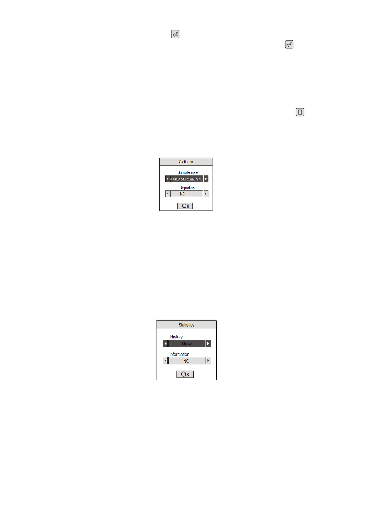
The hardness tester enables the user to perform on-line calculation of the average value of measurement series
results, inter alia, with rejection of the results of incorrectly performed measurements by user-selected algorithm.
The hardness tester enables the user to perform on-line additional statistical processing of measurement series
results, namely, retrieval of minimum, maximum values, calculation of average value and calculation of mean square
deviation from the average value.
The hardness tester enables the user to perform on-line displaying of additional information, namely, results of the
preceding measurement series.
The hardness tester enables the user to organize data storage in the form of individualized blocks of measurement
results, to store them with power off and to transfer the data to the computer.
The hardness tester enables the user to perform various types of stored measurement results analyses, to plot
various types of charts directly on display.
The hardness tester enables the user to select information additionally displayed in the course of measurements.
The hardness tester enables the user to set up checking range and to set up measurement range overrun alarm.

4
The hardness tester enables the user to perform battery charge monitoring and to set up battery discharge alarm.
The hardness tester enables the user to set up automatic device tripping during timeout in order to save battery
charge.
The hardness tester enables the user to adjust display illumination so as to save battery charge.
The hardness tester enables the user to select required display color and intensity range.
The hardness tester enables the user to select interface language from those preset by the manufacturer on user’s
request.
1.4Technical Characteristics
Basic technical characteristics.
Basic technical characteristics of the hardness tester are listed in Table 1.
Table 1.
Hardness measurement range by scales:
Brinell
90 - 450 НВ
Rockwell С
20 - 70 HRC
Vickers
240 - 940 HV
Limits of hardness measurement absolute error, main scales:
Brinell
Within (90...150) НВ
±10 НВ
Within (150...300) НВ
±15 НВ
Within (300...450) НВ
±20 НВ
Rockwell С
±2 HRC
Vickers
Within (240...500)HV
±15 HV
Within (500...800)HV
±20 HV
Within (800...940)HV
±25 HV
Hardness measurement range, reference scales:
Ultimate tensile strength
350…1500 MPa
Rockwell А
70,5 - 85,5 HRА
Rockwell В
51 - 100 HRВ
Shore D
35 - 102 HSD
Hardness tester electronic unit overall dimensions, maximum
Model type ТКМ-459С
121 х 69 х 41 mm
Hardness tester electronic unit mass:
Maximum
0,3 kg
Mass of the sensors
Maximum
0,3 kg
Hardness tester rated operation conditions
Air temperature
From minus 15 to plus 35 °С
Relative humidity
30 –80 %
Atmospheric pressure
84 –106,7 kPa
Calibration period
1 year
Hardness tester service life
5 years
Number of hardness tester potential additional calibrations
Model type ТКМ-459С
5 for each scale
Hardness tester additional scales number
Model type ТКМ-459С
3
Duration of one hardness measurement cycle (average)
2 s
Number of measurement cycles required to calculate the average value
Model type ТКМ-459С
1 –99
Number of algorithms of incorrectly performed measurement results
rejection in the course of average value calculation
3
Parameters of additional statistical processing of measurements
series
Maximum, minimum, mean square deviation from
average value, average value.
Additional information displayed (to be defined by the user)
Model type ТКМ-459С
Previous results of the measurements series, results of
additional statistical processing
Number of samples required to set up additional calibrations for
hardness tester scales
1 or 2
Number of samples required for additional scales set up
2 to 0 (to be defined by the user)
Intermediate interpolation of additional scales
Piecewise linear or piecewise –parabolic (to be defined
by the user)
Measurement results overrunning alarm (model type ТКМ-459С
only)
Color. Check limits to be set up by the user for each
individual scale. Types of limits: greater, less, overrun.
Maximum number of measurements stored in the memory

5
Model type ТКМ-459С
12 400
Maximum number of individualized blocks set up in the memory
Model type ТКМ-459С
100
Displaying, statistical processing and plotting of charts of the measurement result blocks
Displaying
all results in the block
results in the block which are greater or less than values set up by the user
results falling outside the specified range set up by the user
Statistical processing
maximum, minimum, mean square deviation from average value, average value
average deviation from the value set up by the user, number of results bigger / less
than specified value, maximum deviation from specified value to bigger/less side
number of results falling outside the range set up by the user (outside bigger/less limit),
maximum deviation from upper/lower limit
Plotting of charts
in reference to average value
in reference to value set up by the user
in reference to measurement range set up by the user
Computer interface connection
USB
Hardness tester automatic turn-off
Turn-off time to be set up by the user
Monitoring of battery charging
Continuously. Continuous indication in the course of measurements
Display illumination
Time to be set up by the user
Display color and intensity
To be selected by the user
Interface language of the hardness
tester
English ( German, French –optionally)
Hardness tester power supply
Autonomous, battery. Use of equivalent non-rechargeable batteries allowed.
1.5Hardness Tester Sensors
The hardness tester incorporates a sensor and an electronic unit which is processing the signals transmitted from the
sensor. Delivery set of the hardness tester may include additional sensors –on user’s request.
Sensors are designed to form the frequency signal which is transmitting information regarding hardness of article
under check.
Sensor is functionally incorporating a casing and a protective cap (ref. Figure А).
Inside the casing there is a resiliently pressed steel shaft with a diamond pyramid and a limit switch which is, being
closed, gives a resonance frequency measurement command. Piezoelectric plates connected with the shaft are
designed to excite and to receive the shaft oscillations.
The cap is designed to protect the shaft from overload and from touching it by foreign particles or user’s hand in the
course of measurements. Where measurements should be performed in hard-to-reach areas it is allowed to remove
the protective cap.
Fig. А.
On user’s request, probes of the hardness tester may be equipped either with additional cap or with special caps
enabling proper positioning of the tester on cylindrical surfaces.
Minimum mass of article under check —1 kg.
Table 6
Probe type
Surface roughness, maximum
А
Ra 1,6
Н
Ra 0,8
С
Ra 3,2
К
Ra 1,6
Minimum radius of curvature of article’s convex surface under check —4 mm.
In order to provide proper positioning of the sensor on convex surfaces subject to check it is recommended to make
use of additional U-459 type cap.
Minimum radius of curvature of article’s concave surface under check —6 mm.
In order to provide proper positioning of the sensor on concave surfaces subject to check it is possible to make use of
specialized caps fabricated on user’s request.
Minimum diameter of area to carry out hardness measurement of article under check —3 mm.

6
1.6General Information
Principle of hardness tester operation is based on ultrasonic contact impedance method –dynamic method of
hardness measurement. Unlike hardness testers based on static principle of operation (stationary hardness testers)
the measurement results are affected not only by metal properties revealed during plastic deformation of metal but
also by other mechanical-and-physical properties. Basically –by modulus of elasticity of metal under check (Young's
modulus
Recommended plate parameters are as follows:
- Mass and thickness —definitely exceeding minimum mass and thickness of article under check.
- Roughness –minimum possible. Optimal - maximum Ra 0.4 µm;
- Non-flatness - maximum 0,005 mm;
- Modulus of plate metal elasticity (Young’s modulus)
Depending on the type of probe used and article hardness the sensor pyramid is penetrating the article at different
depths plastic deformation of metal takes place at considerably larger depths. It is recommended to measure
hardness of the layer with thickness which is minimum by 5 times exceeds pyramid penetration depth.
1.7Hardness Tester Menu
Menu image is presented in Figure 2.
Fig. 2
Switching between menu points is performed with the use of buttons “ ”, “ ”. Selection of the menu point
(changeover to parameters setting or to sub menu) is performed by button . The display will accordingly show
parameter entry window (see below) or sub menu. Exit from sub menu to a higher level –by button “”.
Number of menu points indicated in the course of operation may differ and depends on what scale (main, reference,
additional) or additional calibration has been selected at the moment.
General structure of the menu is represented in Table 8.
Entry to the menu is performed by pressing button “ ”The hardness tester being turned on displays only points —
<Settings>, <Memory>, <Turn off>.
1.8Settings Entry Mechanism
Settings and parameters of hardness tester operation are entered through parameters entry window:
–By selecting one of several possible setting options (for instance, averaging value);
–By entry of numeric or string value (for instance, additional scale name)
Example of parameter entry window is shown in Figure 3.
Fig. 3
In order to measure parameter 1 it is required to select it on the display with the use of buttons “ ”, “ ”. The
selected parameter is shown on the display.
Parameter 1 is set up by selecting one of several options. To change it, use buttons “ ”, “ ”.
Parameter 2 is set up by entering the numerical value. To change it, select it on the display and press button “ ”.
Display is represented by Figure 4.
Fig. 4
Numerical value entry is performed by digit order selection in cursor position. Digit in respective digit order is changed
by buttons “ ”, “ ”. Transition to other digit order is performed by buttons “ ”, “ ”. Entry of numerical value is

7
completed by pressing button “ ” (cursor disappears, parameter 2 remains selected). Entry of string parameters is
performed similarly.
Exit from parameters set up window to the menu is performed by pressing button “ ”. Exit may be also performed by
pressing button “ ” provided that at this moment there is no parameter set up by numerical or string value entry.
One more way to exit the entry window –select “ОК” button image on display and press button “”.
2OPERATION
2.1Hardness Measurement Procedure
Carefully, WITHOUT IMPACT place the sensor normally (perpendicularly) to surface of article to be checked;
Smoothly pressing the sensor casing (pressing the sensor spring) dent the diamond pyramid into the surface to be
checked;
After acoustic signal comes on and previous measurement results go off from hardness tester display (it should take
place within a fraction of a second) REMOVE the sensor from the surface of article under check;
Results of hardness measurement will appear on the display approximately within 1 second.
After acoustic signal comes on avoid keeping the sensor on surface under check. Entire cycle of measurement (from
pyramid touching the surface till unsticking) may be maximum 1 second.
Energize the hardness tester instantly pressing button “”.Generally, the display image will be as follows, Figure 8.
Fig. 8
The display will show device settings menu if hardness tester is energized without sensor.
2.2 Control and Results Submission in the Course of Measurements
When the device is energized (by instantaneous pressing of button “”) with sensor connected the display will have
image represented in Figure 9 depending on operation cycles, averaging parameters, scale selected or additional
statistics set up at previous operation cycles.
Fig. 9
Select the scale with the use of buttons “ ”, “ ”, at this, scale names and units of measure will be respectively
displayed.
Quick selection of main scales may be performed by buttons “ ”, “ ”, “ ”.
The hardness tester will convert the results into respective scale after scale selection.
Additional calibrations to scales are selected by buttons “ ”, “ ”, at this, scale calibration names will be
respectively displayed.
Additional statistical processing—i.e. definition of maximum, minimum, average value (without “rejection”), mean
square deviation from the average value.
Measurement series extent (sample size, number of measurements in the series) is selected in the menu button “”.
If number of measurements is considerable it is supposed that only a number of recent results will be displayed. With
activated field of additional statistical processing (see below) it is supposed than 7 recent (otherwise 12) results will be
displayed.
The field is automatically cleared before new measurement series commencement. If sample size 1 is selected the
field will be cleared after instantaneous pressing of button “ ”
Filed “additional statistics” displays on-line results of additional statistical processing;
Max –maximum result in the series;
Min –minimum result in the series;
Х —average value (calculated without the use of algorithms of incorrectly performed measurement results rejection);
—mean square deviation from the average value.

8
The field is automatically cleared at new measurement series commencement. If sample size 1 is selected the field
will be cleared after instantaneous pressing of button“”.
Measurement result recording in device memory is carried out by pressing and holding button “ ”. In this case, the
hardness tester will transmit a specific acoustic signal and result displayed will “blink”.
If, during button pushing, the series of measurements is still in progress the hardness tester will first complete the
current series of measurements, as described above, calculate average value of the entire series –deliver the result
of the measurement - and record the result in memory. If sample size is equal to 1 it is supposed that total statistics
will be deleted and the last result will be recorded.
In device, results falling outside the specified limits (thresholds) are indicated by special colors provided that
monitoring limits have been set up
Field “battery charge indicator”is displaying the on-line battery charge condition.
Switchover to the menu so as to perform settings is achieved by instantaneous pressing of button “”.
Set up of statistical processing parameters in the course of measurements
2.3Set up of Averaging Parameters
In order to set up the size of series of measurements (sample size) and algorithm of incorrectly performed
measurement results rejection it is required to select menu points <STATISTICS> - <SAMPLE>
Fig. 10
The display will show parameter input window in conformity with Figure 10.
Sample size which can be set up - 1.2.3.4.5.6.7.8.9.10.15,”continuously”. If “continuously” is selected, it is supposed
that sample size will not be capable to exceed maximum number of measurements while calculating the average
value for the given model type.
In field “Rejection”select the algorithm of incorrectly performed measurement results rejection. Possible options:
“NO” –while calculating the average value - rejection is not performed;
“2σσ” –while calculating the average value –results which are more than two mean square deviation values distant
from average value of the current measurement series are rejected;
“EXTREME” –maximum and minimum (if 5 and more measurements in the series) values are rejected.
2.4Additional Statistics Displaying
In order to set up displaying of the history of measurement series results and additional statistical processing results it
is required to select menu points <STATISTICS> - <INFORMATION>.
Fig. 11
The display will show parameters entry window according to Figure 11.
By field “History”the user whether selects or not (in the course of measurements) the history of measurement results
in the series.
By field “Information” (available with model type ТКМ-459С only) the user whether selects or not displaying of
additional statistical processing results.
If “Show”option is selected it is supposed that respective information will be displayed in the course of measurements.
If “NO” option is selected it is supposed that information will not be withdrawn to the display.
2.5Set up of Control Range
In order to set up the control range with overrun alarm it is required to select menu point <THRESHOLDS>.
The following alarm signals may be used:
Alarm off;
Result above threshold;
Result below threshold;
Alarm indicating measurement result overrunning the definite range;

9
Depending on the selected option, the data entry window may be represented as follows.
Figure 12.
Field “Alarm” is used to select the type of alarm. Digital fields are used to enter the threshold values Hardness tester
scales calibration
2.6Calibration of the Scale
To enter calibration mode select proper scale of the hardness tester enter the MENU and select <CALIBRATION> - <
CALIBRATION>. İt is supposed that hardness tester display’s image will be in conformity with Figure 13.
Fig. 13
Carry out several measurements (minimum 5) on test block at this, measurement results will be displayed in “results”
field while “test block 1” field will display
By buttons “ ”, “ ” change average reading values to reach value of the test block and thus terminate calibration
with one (first) test block pressing button “ ”after that display will be represented by image below (Figure 14).
Fig. 14
On the second test block. Apply same procedure and press button “ ”. The display will show the message
confirming completion of calibration with two test blocks and after that hardness tester will return to the menu.
Fig. 15
During sample measurements, the display will show measurement result (sensor signal expressed in relative units),
results of previous measurements (in field “history of measurements”), number of measurements and average value.
Averaging is performed with the use of algorithm of incorrect measurement results rejection.
Pressing of button “” will lead to previous measurements “setting to zero” and commencement of new averaging
cycle.
Exit from operation mode to the menu pressing button “”.
2.7Hardness Tester Electronic Unit Settings
Set up of automatic device and display illumination turn-off.
The hardness tester enables the user to set up device automatic and display illumination turn-off time during time
outs. Well-considered setting of the said parameters allows to provide User’s comfort and save the battery charge.
To change the above settings select <SETTINGS> - <DEVICE>. In the entry window that appears make respective
settings
Set up of display colors and intensity.

10
The hardness tester allows setting up the display colors and intensity. Well-considered setting of the said parameters
allows to provide User’s comfort and save the battery charge.
To change the above settings, select <SETTINGS> - <DISPLAY>. In the entry window that appears make respective
settings.
2.8Language Selection
The hardness tester allows to select interface language from those uploaded by the manufacturer (on user’s request).
To choose the language select <SETTINGS> - < LANGUAGE SELECTION >. In the entry window that appears make
respective settings.
2.9General Information
The hardness tester enables the user to organize versatile measurements data archive in hardness tester memory
and transfer the data to the computer.
The archive is organized in the form of individualized memory blocks. Results of measurements are recorder into the
memory blocks. Memory block may contain results of measurements in similar units of measure (by one scale).
Operations that may be performed with data archive are as follows:
-set up of memory blocks;
-Deletion of memory bocks;
-clearing of memory blocks;
-set up of measurement results record blocks;
-set up of memory block names;
-Data withdrawal to the display;
-Withdrawal of data satisfying pertinent requirements to the display
-Data analysis by means of various statistical processing methods
-Data analysis with the use of charts displayed
-Data archive clearing;
-monitoring of device memory state
-Data transfer to the computer.
Access to data archive handling is achieved via <MEMORY> point in hardness tester menu
Set up of the block
In order to set up the new data block select <MEMORY> - <BLOCK SET UP>.
In parameters entry window that appears set up the name of the new block together with units of measure
corresponding to the scale.
If it is impossible to set up the block (hardness tester memory full or maximum number of blocks had been set up) the
hardness tester will deliver a respective message.
Set up of measurement results recording block
In order to select data block for measurement results recording select <MEMORY> - <SELECT THE BLOCK >.
The display will show the list of data blocks (Figure 16) which can be selected for measurement results recording in
the current scale (may contain data expressed in current units of measure).
Fig. 16
By buttons “ ”,” ”,” ” select the data block to record the measurement results according to the current scale.
If there are no result measurement blocks earlier set up in units of measure of the current scale the hardness tester
will issue a dialog messageproposing to set up such block.
Another way to set up results recording block –select <MEMORY> - <DATA BLOCKS>. Select the necessary block.
Select (in submenu) <SELECT> point. The block selected will be set up to measure the results with reference to
respective scale.
Block clearing
To delete all data from the block, select <MEMORY> - <CLEAR THE BLOCK>. By buttons available (“ ”,” ”,” ”)
select the necessary block out of list of blocks available and confirm the selection. The block will be cleared.
Another way–select <MEMORY> - <DATA BLOCKS>. Select the necessary one out of list of blocks available. Select
in submenu <CLEAR> point.
Deletion of the block
In order to delete data block from the memory, select the points <MEMORY> - <DELETE THE BLOCK >. Select the
necessary one out of list of blocks available and confirm the selection. The block will be deleted.
Another way–select <MEMORY> - <DATA BLOCKS>. Select the necessary one out of list blocks available. Select in
submenu <DELETE> point.

11
Clearing of the memory
In order to delete all data blocks from the memory, select <MEMORY> - <CLEAR THE MEMORY >, confirm the
selection. The memory is cleared.
Memory state information
To receive information on current memory state select <MEMORY> - <STATE>.
Display will have image in conformity with Figure 17.
”
Fig. 17
In “Blocks”field: “Actually set up” – total number of data blocks actually set up. “Feasible”– maximum number of data
blocks which may be set up as of the present moment.
In “Result” field –total number of measurement results recorded. “Reserve” – number of memory cells reserved for
measurement results recording in available data blocks. “Feasible” – number of free memory cells not yet reserved for
the data blocks.
Exit to menu –press button “” or””.
Change of block name
In order to change data block name, select <MEMORY> - <DATA BLOCKS>. Select the necessary one from the list of
blocks. In submenu that appears select <NAME>. In parameters entry window set up the new name according to
requirements set forth.
Data viewing
To view results of measurements recorded in memory block select <MEMORY> - <DATA BLOCKS>. Select the
necessary one from the list of blocks. Select <RESULTS>.
Model type ТКМ-459М will provide displaying of all measurement results recorded in selected data block. In order to
scroll the list, use buttons “ ”,” ”. Exit to menu using button “” or” ”
Model type ТКМ-459С –in parameters entry window (ref. Figure 18) select the condition of recorded results
withdrawal to the display and set up limit values according to the requirements set forth.
Fig. 18
The following selection options can be used:
-displaying of entire results;
-displaying of results exceeding the specified value;
-displaying of results below the specified value;
-displaying of results falling outside the specified range;
After set up of specified values, it is supposed that device display will show the list of entire measurement results
satisfying the condition selected, or else, the hardness tester will give a message that such results were not found.
Data Analysis
The hardness tester allows carrying out different types of recorded measurement results analysis:
-Calculation of average value, mean square deviation from average value, retrieval of minimum and maximum values
(view -“AVERAGE”);
-Calculation of average deviation from specified value (for instance, hardness value anticipated) upwards or
downwards, retrieval of maximum deviation upwards or downwards (view -“VALUE”);
-In reference to the range (view -“RANGE”).
In order to enter measurement results processing mode select <MEMORY> - <DATA BLOCKS>. Select the required
data block from the list. In submenu that appears select <ANALYSIS>.
In parameters entry window that appears select analysis type (“AVERAGE”,”VALUE”,”RANGE” –analysis type
required) and initial values required.The display will show required calculations results.
Graphical Output
The hardness tester allows analyzing the stored results with the use of charts plotted on the display. For the ease of
analysis, the charts may be plotted:
-In reference to average data value in the data block;
-In reference to value specified (for instance anticipated hardness);

12
-In reference to values range (for instance for instance, admissible hardness range).
To enter charts plotting mode, select <MEMORY> - <DATA BLOCKS>. Select the necessary one from the list. In
submenu that appears select <CHART>.
In parameters entry window that appears select the chart type (“AVERAGE”,”VALUE” or “RANGE”) and initial values
required.
The display will show the chart plotted according to data block. Horizontal lines specify initial values.
Data Transfer to the Computer
To transfer data to the computer use cable included in the delivery set and connects the hardness tester with the
computer. Set up the software supplied with the hardness tester.
After that:
-energize the hardness tester;
-connect (to the plug located on electronic unit side wall) the data transfer cable included in delivery set. Connect
other cable end to one of computer USB ports. The display will show that it is connected to the computer;
-start up the software.
2.10Battery Condition Monitoring and Charging
The hardness tester enables the user to perform on-line battery condition monitoring. Current battery charge is
displayed in the course of screen.
When critical battery discharge is achieved, the display will show the blinking warning symbol of the battery followed
by an acoustic signal and the hardness tester will turn off.
To charge the battery, open the battery compartment, remove the battery and charge it using battery charger included
in the delivery set.
To charge the battery, connect battery charger to the plug located on electronic unit sidewall and charge the battery.
The display will keep showing battery symbol in the course of charging.
ATTENTION!!!
During charging don’t’ leave the charger unattended.
2.11Hardness Tester Turning Off
The hardness tester may be turned off:
-By pressing and holding (0, 5-1s) of button “ ” with further releasing;
-By selecting <TURN OFF> in the menu;
-By omitting any activities (measurements, buttons activating). The hardness tester will turn off.
3MANUFACTURER’S WARRANTY
Hardness tester guarantee period amounts to 24 months from the date of purchasing
Guarantee and post-guarantee repairs are carried out at manufacturer’s facilities.
Hardness testers which have damages caused by the violation of operation, safety, technical maintenance,
transportation and storage regulations, mechanical damages (with exclusion of mechanical wear caused by normal
operation), traces of liquids ingress and other impacts leading to hardness tester breakdown are not subject to
guarantee repairs.
Hardness testers which have diamond pyramid shearing evidence are not subject to guarantee repairs.
Hardness testers which have broken protective seals (stickers) on electronic unit and sensor casings as well as
hardness testers having evidence of unattended opening and/or unauthorized repair attempts are not subject to
guarantee repairs.
Manufacturer’s warranty is not covering batteries and appliances of third party manufacturers (chargers, grinding
machines) supplied in one delivery set with the hardness tester.
Manufacturer’s warranty is not covering natural wear of hardness tester components (cables, sensors etc.) caused by
heavy duty operation.
The guarantee repair will be carried out against presentation of this Operation Manual supported by the technical
passport of the hardness tester.
Table of contents
Other Bms Bulut Makina Measuring Instrument manuals
Popular Measuring Instrument manuals by other brands

CRE Technology
CRE Technology PM-PROGRESS Technical documentation

promesstec
promesstec UDA 50-U Series user manual

GREWIN
GREWIN EPM300A-1BY user guide

Alicat Scientific
Alicat Scientific M quick start guide

Gossen MetraWatt
Gossen MetraWatt SECULIFE ITBASE operating instructions

John Bunn
John Bunn DigiO2 Operation manual