BMS TAA-101 User manual

TAA-101/TAA-101S ANTENNA ACTUATOR
Installation/Operation Manual
Doc. No. 605169301 Rev. N

Broadcast Microwave Services, Inc. ▪12367 Crosthwaite Circle, Dock 10 ▪Poway, CA 92064 ▪USA
Tel: +1 (858) 391-3050 ▪Toll-free (US): 800-669-9667 ▪Fax: +1 (858) 391-3049 ▪support@bms-inc.com ▪www.bms-inc.com
Broadcast Microwave Services Europe GmbH & Co. KG ▪Schwalbacher Str. 12 ▪65321 Heidenrod Germany Tel: +49-6124-72
39-00 ▪Fax: +49-6124-72 39-29
2011 Broadcast Microwave Services. All rights reserved.
This document and the information contained in it is the property of Broadcast Microwaves Services, Inc. and may be the subject of
patents pending and granted. It must not be used for commercial purposes nor copied, disclosed, reproduced, stored in a retrieval
system or transmitted in any form or by any means (electronic, mechanical, photocopying, recording or otherwise), whether in whole
or in part, without BMS prior written agreement.

TAA-101/TAA-101S Antenna Actuator Manual | Doc. No. 605169301 Rev. M
Broadcast Microwave Services, Inc. i
Document Revision History
Initial release 2006 Rev. -
Subsequent updates 2006-2008 Rev. A through G
Added Figure 9, Caution, page 15 March 2009 Rev. H
Added installation and removal tool instructions, starting page 18 October 2009 Rev. J
Updated max speed figure to correspond to STC. January 2010 Rev. K
Updated speed, deployment figures based on new calculations; added drawings March 2010 Rev. L
Included TAA-SM-22 (P/N 8001272972) November 2010 Rev. M
Adjusted RF exposure distance due to latest test reports August 2011 Rev. N
Conventions Used in This Manual
NOTE: Notes provide supplementary information. They are highlighted for emphasis, as in this
example, and are placed immediately after the relevant text.
CAUTION: Cautions give information which, if strictly followed, will prevent damage to equipment or
other goods. They are boxed for emphasis, as in this example, and are placed immediately preceding
the point at which the reader requires them.
WARNING: Warnings give information which, if strictly observed, will prevent personal injury or
death, or damage to personal property or the environment. They are boxed and shaded for emphasis,
as in this example, and are placed immediately preceding the point at which the reader requires
them.
ATTENTION!
CAUTION: DO NOT use right-angle connectors or adapters on the RF Power Out cable assemblies.
Right-angle connectors may have significant RF power loss at the operating frequencies of this
system.
CAUTION: FOR ALL BMS TRANSMITTERS: Operation of this product generally requires a license.
It is the responsibility of the user to obtain all required operating licenses.
FOR PRODUCTS AWAITING FCC CERTIFICATION: This device has not been authorized as required
by the rules of the US Federal Communications Commission. This device is not, and may not be,
offered for sale or lease, or sold or leased, in the US until authorization is obtained.
NOTE: Actual Acceptance Test Procedure (ATP) Test Data results by product serial number are
shipped with all units and indicate the equipment to be operating within advertised specifications.
Read and Follow Instructions
All safety and operating instructions should be read before this product is operated. All operating and use
instructions should be followed. This manual should be retained for future reference.
EMC Compliance
This equipment is certified to the EMC requirements detailed in the technical specifications. To maintain
this certification, only use the cables supplied or if in doubt contact BMS Customer Service.

TAA-101/TAA-101S Antenna Actuator Manual | Doc. No. 605169301 Rev. M
Broadcast Microwave Services, Inc. ii
RF Exposure Information
For body worn operation, the device has been tested and meets FCC RF exposure guidelines when used
with an accessory that contains no metal and that positions device a minimum of 57 cm (when a 6dBi
antenna is used) from the body. Use of other accessories may not ensure compliance with FCC RF
exposure guidelines.

TAA-101/TAA-101S Antenna Actuator Manual | Doc. No. 605169301 Rev. M
Broadcast Microwave Services, Inc. iii
Contents
1
INTRODUCTION...................................................................................................................................................1
2
SYSTEM DESCRIPTION......................................................................................................................................2
2.1
TAA-101 and TAA-101S Components and Accessories...............................................................................5
2.2
Technical Specifications...............................................................................................................................8
3
INSTALLATION/SETUP.....................................................................................................................................21
3.1
Deciding the Component Locations............................................................................................................22
3.2
Installing the Mounting Bracket...................................................................................................................22
3.3
Cable Routing.............................................................................................................................................23
3.4
Installing the Up/Down Box.........................................................................................................................23
3.5
Cable Termination ......................................................................................................................................24
3.6
Antenna Installation....................................................................................................................................24
3.7
Installing the Antenna Actuator (TAA-101 or TAA-101S)............................................................................24
3.8
Removing the Antenna Actuator (TAA-101 or TAA-101S)..........................................................................27
4
USER INTERFACE.............................................................................................................................................29
5
OPERATION.......................................................................................................................................................30
6
PREVENTIVE MAINTENANCE..........................................................................................................................31
6.1
Maintenance Schedule...............................................................................................................................31
6.2
Maintenance Procedures............................................................................................................................31
7
WARRANTY .......................................................................................................................................................33
7.1
Customer Service Information....................................................................................................................33
8
TROUBLESHOOTING........................................................................................................................................34
8.1
Connector Pin-outs.....................................................................................................................................34
List of Figures
Figure 1. Cross-tube strut mount....................................................................................................................................3
Figure 2. Low profile skid mount ....................................................................................................................................4
Figure 3. Low profile and 4-inch lift skid mounts ............................................................................................................4
Figure 4. Low profile skid mount outline drawing ...........................................................................................................7
Figure 5. Four-inch lift skid mount outline drawing.........................................................................................................8
Figure 6. TAA-101 left side mount (LSM).......................................................................................................................9
Figure 7. TAA-101 right side mount (RSM)..................................................................................................................10
Figure 8. TAA-101S .....................................................................................................................................................11
Figure 9. TAA-101, left side, exploded view.................................................................................................................12
Figure 10. TAA-101 outline drawing.............................................................................................................................13
Figure 11. Weldment, Hughes 300, skid mount, low profile omni deployment.............................................................14
Figure 12. Bell 412 with 4.0" lift skid mount, weldment................................................................................................15
Figure 13. TAA-101 retract/deploy switch schematic...................................................................................................16
Figure 14. Typical wiring, TAA-101 in analog application.............................................................................................17
Figure 15. Up-Down Box deployment control (analog).................................................................................................18
Figure 16. Typical wiring, TAA-101 in digital application..............................................................................................19
Figure 17. TAA-101 drag vs. speed graph...................................................................................................................20
Figure 18. TAA-101 interconnect diagram ...................................................................................................................21
Figure 19. Cross-tube mount assembly .......................................................................................................................23
Figure 20. Actuator Installation and Removal tools......................................................................................................25
Figure 21. Position of detent pins.................................................................................................................................25
Figure 22. Aligning the actuator (sealed actuator shown)............................................................................................26
Figure 23. Using the actuator installation tool ..............................................................................................................26
Figure 24. Actuator correctly mounted.........................................................................................................................27
Figure 25. Using the actuator removal tool on forward and rear pins...........................................................................28
Figure 26. Up/Down Box interface ...............................................................................................................................29
Figure 27. Alternate deployment control ......................................................................................................................29
Figure 28. Product label...............................................................................................................................................33

TAA-101/TAA-101S Antenna Actuator Manual | Doc. No. 605169301 Rev. M
Broadcast Microwave Services, Inc. iv
List of Tables
Table 1. TAA-101 components and accessories............................................................................................................5
Table 2. Actuator mounting bracket assemblies.............................................................................................................6
Table 3. Antenna actuator characteristics......................................................................................................................8
Table 4. Deployment control unit....................................................................................................................................8

TAA-101/TAA-101S Antenna Actuator Manual | Doc. No. 605169301 Rev. M
Broadcast Microwave Services, Inc. v
Page left intentionally blank

TAA-101/TAA-101S Antenna Actuator Manual | Doc. No. 605169301 Rev. M
Broadcast Microwave Services, Inc. 1
1 INTRODUCTION
The TAA-101 Antenna Actuator Assembly deploys an omni-directional antenna below the aircraft allowing
unrestricted views between the omni and ground sites. Both the TAA-101 and the TAA-101S are
designed to avoid line-of-sight obstacles created by aircraft features that might interfere with
transmission. This greatly enhances continuous communication between the helicopter and its associated
transmit and/or receive site. The TAA-101S Antenna Actuator is sealed for harsh environments.
This dependable low cost antenna actuator may be skid- or cross-tube-strut mounted. A breakaway
release mechanism assures safety if the antenna is still deployed when the helicopter lands.
Features:
•Low cost
•Lightweight
•360°azimuth coverage
•Quick installation
•In-flight deployment
•Stows for landing
•TAA-101S for harsh environments
•Deployed/stowed indicators
This document provides instructions for the installation, operation and maintenance of both the TAA-101
and the TAA-101S Antenna Actuator Assemblies.
NOTE: A safety placard is referenced in the relevant STC. The placard’s BMS part number is
200169303.
Broadcast Microwave Services (BMS) is a leader in wireless digital microwave technology providing
innovative products for the television broadcast, video, telemetry and surveillance industries. A wholly
owned subsidiary of Cohu, Inc., BMS designs and manufactures a comprehensive line of microwave
communications equipment for broadcasting sports venues, law enforcement and military applications.
BMS also builds and integrates command and control centers to provide fully functioning, complex, end to
end digital systems.
For the latest product and system information please visit www.bms-inc.com.
Broadcast Microwave Services, Inc.
12367 Crosthwaite Circle, Dock 10
Poway, CA 92064
Tel: +1 (858) 391-3050
Toll-free (US only): 800-669-9667
Fax: +1 (858) 391-3049
Web: www.bms-inc.com

TAA-101/TAA-101S Antenna Actuator Manual | Doc. No. 605169301 Rev. M
Broadcast Microwave Services, Inc. 2
2 SYSTEM DESCRIPTION
The TAA-101 and TAA-101S Antenna Actuator Assemblies consist of the Antenna Actuator that deploys
the antenna; a Bracket Mount Assembly used to attach the Actuator to the Helicopter; the Up/Down Box
to control the actuator; and the interconnection cables.
The main components of the Antenna Actuator are a gear head motor, worm and worm gear assembly.
The gear head motor is pinned to the worm and drives the worm gear when the motor is energized with a
24 to 32 volt dc signal. The motor/worm combination in turn drives the worm gear assembly. The polarity
of the dc signal determines the direction that the motor turns. Therefore, connecting dc of one polarity will
deploy the antenna, and reversing the polarity will stow the antenna. At both ends of the travel of the
worm gear, a roll pin in the side of the worm gear actuates a limit switch. When the switch is opened the
power to the motor is disconnected and the unit will remain in this position until a command is given
(reversed polarity voltage) to move in the opposite direction. The worm/worm gear combinations are of
the type that cannot be back driven; therefore power is not required to maintain the position of the
antenna. The Antenna Actuator is available in sealed and non-sealed versions as well as configurations
for left or right side mounting depending on the application.
The Antenna Actuator Assembly has two hardened steel pins on the side of the unit, which snap into
sockets on the Bracket Mount Assembly. The Bracket Mount Assembly has spring-loaded release pins
that retain the Antenna Actuator Assembly. This is to provide a weak link to protect the aircraft in the
event the helicopter is landed with the antenna deployed. The release pins allow the Antenna Actuator to
detach to prevent damage to the helicopter.
CAUTION: Landing with the antenna deployed will damage the antenna.
When the actuator is in the stowed position the omni is parallel to the skid and above ground level and
does not interfere with take off or landing of the helicopter.
There are several types of Bracket Mount Assemblies depending on the application. This document
applies to the cross tube strut mount and skid mount assemblies:
•a cross-tube strut mount bracket assembly (Figure 1):
oP/N 810140225 – 2.25” dia.
oP/N 810140250 – 2.50” dia.
oP/N 810140260 – 2.60” dia.
•a low profile skid mount bracket assembly;
•a low profile skid mount bracket assembly with BMT75 mount;
•a 4-inch lift skid mount bracket assembly.
The cross-tube strut mount bracket assembly (Figure 1) attaches to the struts of the helicopter.

TAA-101/TAA-101S Antenna Actuator Manual | Doc. No. 605169301 Rev. M
Broadcast Microwave Services, Inc. 3
Figure 1. Cross-tube strut mount
TAA-101/TAA-101S Antenna Actuator Manual | Doc. No. 605169301 Rev. M
Broadcast Microwave Services, Inc. 4
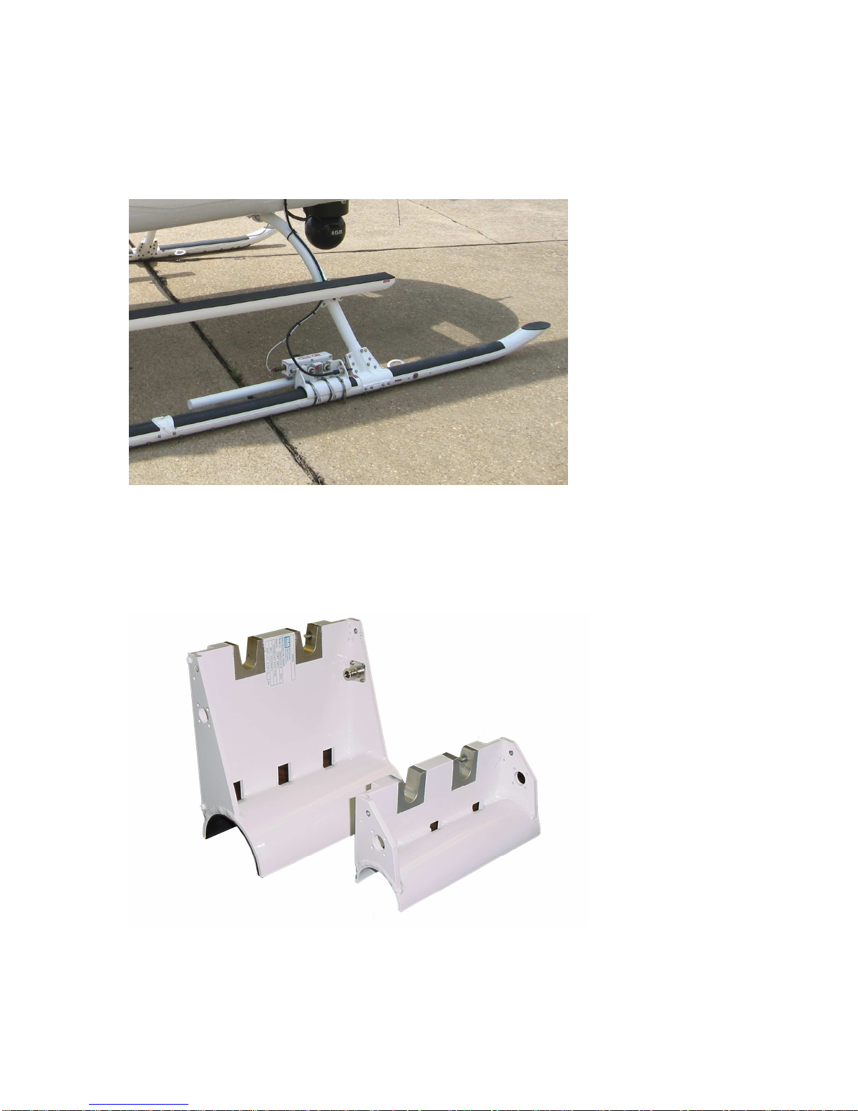
The low profile skid-mount bracket assembly (Figure 2) is attached to the helicopter skid by using
stainless steel clamps. Since the skid diameters vary on the different makes of helicopters, bracket
assemblies are available to accommodate several of the more popular helicopters.
Figure 2. Low profile skid mount
The low profile bracket assembly with BMT75 mount functions the same as the low profile bracket and
has a place to mount a BMS BMT75 transmitter directly to the bracket.
The 4-inch lift skid mount bracket assembly (Figure 3) is a taller version of the low profile bracket
assembly, it functions the same but the 4-inch lift provides an advantage in some applications.
Figure 3. Low profile and 4-inch lift skid mounts

TAA-101/TAA-101S Antenna Actuator Manual | Doc. No. 605169301 Rev. M
Broadcast Microwave Services, Inc. 5
Deployment of the antenna actuator is controlled by the Up/Down Box which also supplies it with power.
There are other deployment control units available as part of an integrated broadcast system (HCP-50,
HCP-100, HCP-50-HCII). Please contact BMS for more information on integrated systems.
2.1 TAA-101 and TAA-101S Components and Accessories
All TAA-101 or TAA-101S assemblies require the antenna actuator, skid mount, and a device for
deployment control. The following table lists the available options and corresponding part numbers.
Table 1. TAA-101 components and accessories
Component Description
Part
Number
Antenna Actuator
Kit, TAA-101-LSM, Left Side Mounting 870169302
Kit, TAA-101-RSM, Right Side Mounting 870169304
TAA-101S-L, Left Side Mounting with RF
cable 800169324
TAA-101S-R, Right Side Mounting with RF
cable 800169323
Deployment
Control
TAA-101-UD Up/Down Box 800195701
Cables
1–7GHz Cable Set 730805000
20” Replacement Cable for TAA-101S
1
610805025
Tools
TAA-101 Installation and Removal Tools Kit 870169391
TAA-101 Installation Tool 800169391
TAA-101 Removal Tool 800169392
1
Replaces the cable from the TAA-101 to the Omni Antenna for both Cable Sets

TAA-101/TAA-101S Antenna Actuator Manual | Doc. No. 605169301 Rev. M
Broadcast Microwave Services, Inc. 6
Table 2. Actuator mounting bracket assemblies
TAA-101 Actuator Mounts with NON-MEMORY Release Pins
Helicopter Skid Diameter
(inches) BMS Part # Type
Hughes 300 2.500 8001272951 Skid Mount
Hughes 500 2.800 8001272952 Skid Mount
MD 500 2.800 8001272952 Skid Mount
Robinson R44 2.800 8001272952 Skid Mount
Bell 206/206B 3.000 8001272953 Skid Mount
Bell Jet Ranger 3.000 8001272953 Skid Mount
Eurocopter EC-120 3.000 8001272953 Skid Mount
Aerospatiale 3.200 8001272954 Skid Mount
Astar AS 350 (B) 3.200 8001272954 Skid Mount
Bell 214B 4.125 8001272955 Skid Mount
Bell 222/230/412 4.125 8001272955 Skid Mount
UH1 Hughie 4.125 8001272955 Skid Mount
Robinson R22 2.000 8001272956 Skid Mount
MD 600 3.500 8001272957 Skid Mount
Eurocopter EC-135 3.750 8001272958 Skid Mount
MD-900 3.320 8001272959 Skid Mount
MD 500/R44 2.800 8001272960 Skid Mount w/
BMT75
Jet Ranger/206B 3.000 8001272961 Skid Mount w/
BMT75
BLIMP 1.500 8001272962 Skid Mount
Eurocopter 1.500 8001272963 Step mount w/
BMT75
Super Puma Mount N/A 8001272964 Belly Mount
Blackhawk N/A 8001272965 Belly Mount
Bell 222/230/412 4.125 8001272966 Skid Mount w/ 4" Lift
Jet Ranger 206B/EC-120 3.000 8001272967 Skid Mount w/ 4" Lift
Aerospatiale 3.200 8001272968 Skid Mount w/ 4" Lift
American Eurocopter BK-
117A3 3.500 8001272969 Skid Mount
American Eurocopter BO-105
3.548 8001272970 Skid Mount
AUGSTA BELL AB-212 3.937 8001272971 Skid Mount
Schweizer Model 333 2.250 8001272972 Skid Mount
TAA-101/TAA-101S Antenna Actuator Manual | Doc. No. 605169301 Rev. M
Broadcast Microwave Services, Inc. 7
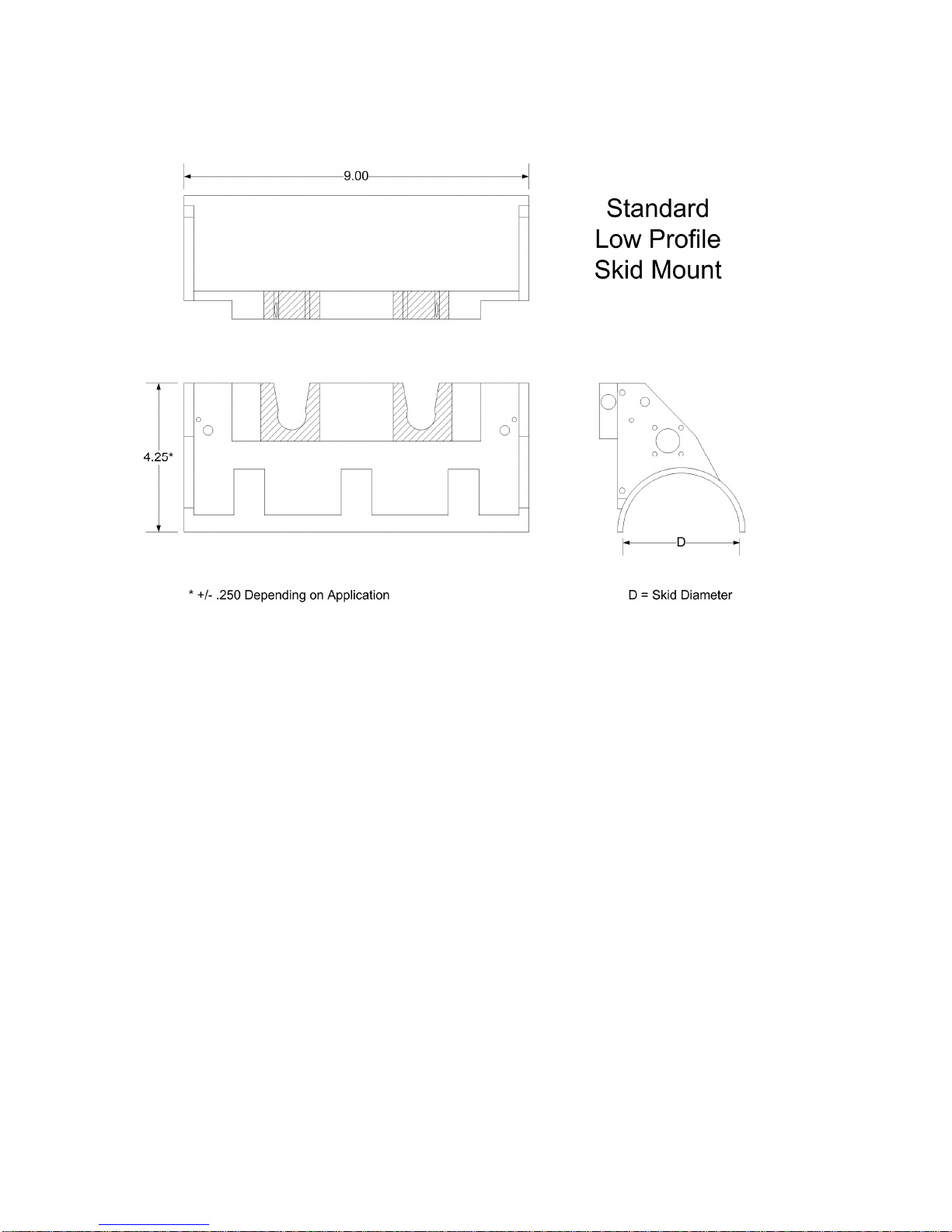
Figure 4. Low profile skid mount outline drawing
TAA-101/TAA-101S Antenna Actuator Manual | Doc. No. 605169301 Rev. M
Broadcast Microwave Services, Inc. 8
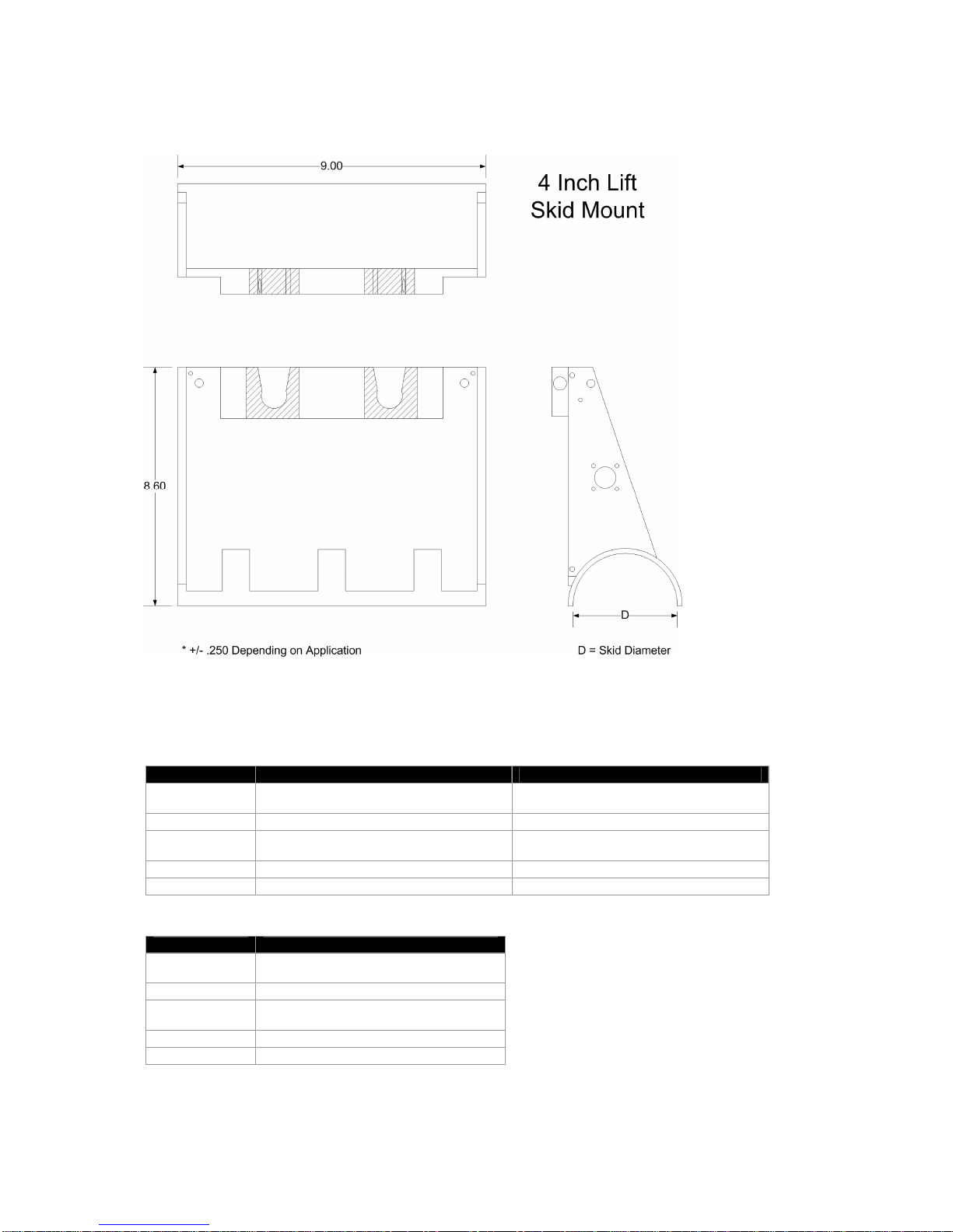
Figure 5. Four-inch lift skid mount outline drawing
2.2 Technical Specifications
Table 3. Antenna actuator characteristics
TAA-101 (Left or Right) TAA-101S (Left or Right)
Size 9.125” x 1.86” x 4.0” (23.18 x 4.72 x 10.16
cm)
8.62" x 1.74" x 4.87" (21.89 x 4.42 x 12.37
cm)
Weight < 5 lbs (2.27 kg) < 6 lbs (2.72 kg)
Voltage
Required 24 – 34 VDC 24 – 34 VDC
Power 32 W Max. 32 W Max.
Operating Temp -4 to + 140 ºF (-20 to +60º C) -4 to + 140 ºF (-20 to +60º C)
Table 4. Deployment control unit
Up/Down Box
Size 3.13” x 1.38” x 1.395” (8.41 x 3.51 x 3.54
cm)
Weight .4 lb (.18 kg)
Voltage
Requi
red
28 – 32 VDC
Power 1 A
Operating Temp -4 to + 140 ºF (-20 to +60º C)

TAA-101/TAA-101S Antenna Actuator Manual | Doc. No. 605169301 Rev. M
Broadcast Microwave Services, Inc. 9
Figure 6. TAA-101 left side mount (LSM)

TAA-101/TAA-101S Antenna Actuator Manual | Doc. No. 605169301 Rev. M
Broadcast Microwave Services, Inc. 10
Figure 7. TAA-101 right side mount (RSM)
TAA-101/TAA-101S Antenna Actuator Manual | Doc. No. 605169301 Rev. M
Broadcast Microwave Services, Inc. 11
Figure 8. TAA-101S

TAA-101/TAA-101S Antenna Actuator Manual | Doc. No. 605169301 Rev. M
Broadcast Microwave Services, Inc. 12
Figure 9. TAA-101, left side, exploded view

TAA-101/TAA-101S Antenna Actuator Manual | Doc. No. 605169301 Rev. M
Broadcast Microwave Services, Inc. 13
Figure 10. TAA-101 outline drawing
This manual suits for next models
1
Table of contents
Popular Antenna manuals by other brands

Hy-Gain
Hy-Gain AV-6160 instruction manual

Hemisphere GPS
Hemisphere GPS Crescent V100 Series Quick reference guide

Spinner
Spinner SISO 1-port-V-Pol Installation

Kenwood
Kenwood SIRIUS CX-SR10 installation manual

D-Link
D-Link ANT70-1800 - Dualband 2.4GHz & 5GHz Indoor/Outdoor... user guide

Intellian
Intellian s130N Installation & Operation User Guide


Sea Tel
Sea Tel 9797A-27 Installation and operation manual

Winegard
Winegard HD6055P Instructions for intallation

COM-power corporation
COM-power corporation AH-640 instruction manual

Mars
Mars MA-CQ26-1X Mounting instructions

Hi-Z Antennas
Hi-Z Antennas Hi-Z 8A-160 manual

Wilson Electronics
Wilson Electronics 301143 installation guide