BMT DH6 User manual

BMT MESSTECHNIK GMBH
BMT MESSTECHNIK GMBH, Stahnsdorf, Germany. Tel. +49 - 3329 - 696 77 - 0, fax +49 - 3329 - 696 77 - 29
OSTI Inc., Monterey, California, USA Tel. +1 - 831 - 649 11 41, fax +1 - 831 - 649 11 51
SAMPLE GAS DEHUMIDIFIER DH6
Manual
Rev. 10/2020

SAMPLE GAS DEHUMIDIFIER DH6 Manual, Rev. 10/2020
2
MDH6EN-10-2020
Sample gas dryer DH6
Contents
1General Description 3
2Cautions & Warnings 4
3Installation 4
4Electrical connection 5
5Display 5
6Error Messages 6
7Low Concentration Version DH6-LC 7
8Maintenance 8
9Specifications 9

SAMPLE GAS DEHUMIDIFIER DH6 Manual, Rev. 10/2020
3
MDH6EN-10-2020
1General Description
The DH6 electric cooler/dryer is a flow-trough cooling device for removing water vapor (or oth-
er vapors) from a sample gas e.g. for photometric measurement of its ozone content. The heat
exchanger is a perpendicular oriented SS tube, cooled from the outside by a Peltier-electric cool-
ing system. The temperature of the inner surface of the tube is automatically controlled to a tem-
perature which can be set between 1ºC and 15°C.
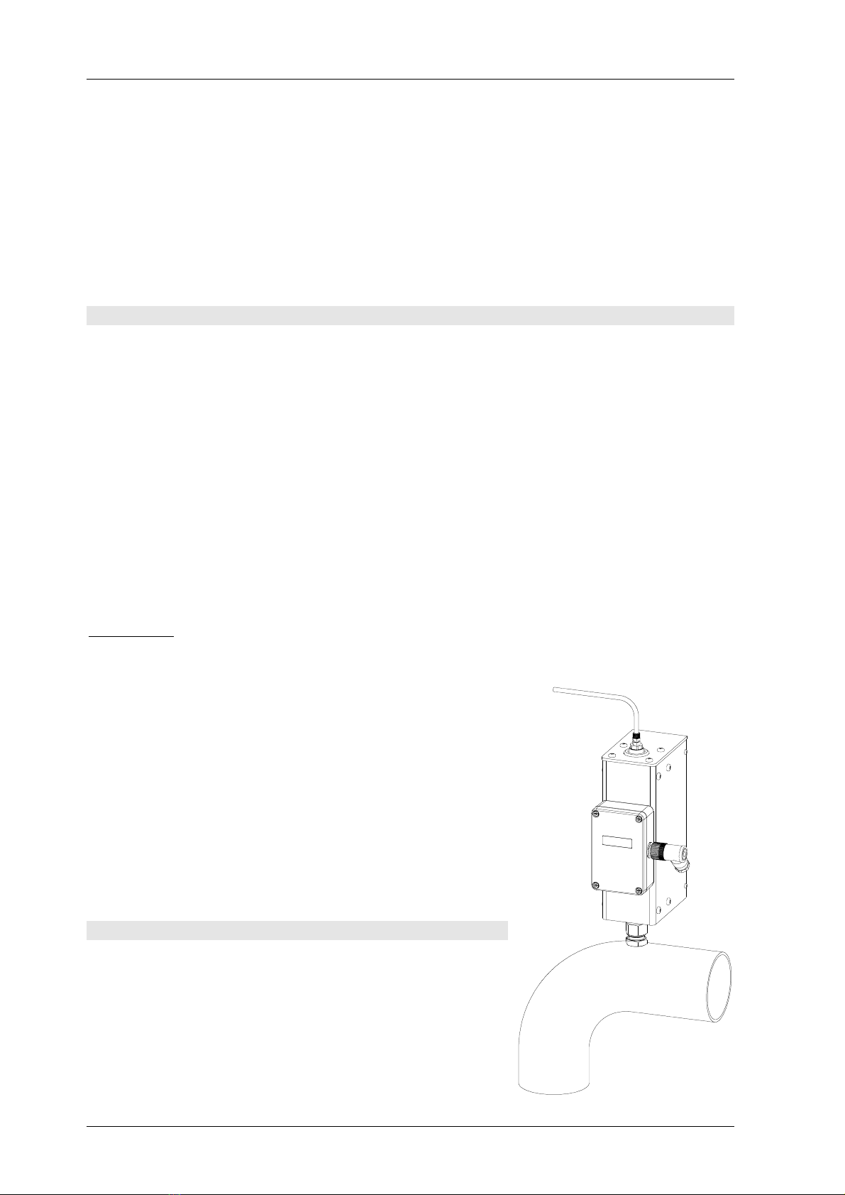
The DH6 is a box about 279x140x64 mm (HxDxW) standing upright on one "leg" (upright posi-
tion is inevitable because the condensate formed inside the cooler has to flow back into the off-
gas system). On top of the reaction vessel, or in a large diameter off-gas tube, the "leg" is plugged
into a big SS fitting with PTFE seal. The fitting can be screwed into a 3/8" NPT threaded bore
hole, or it can be welded into a bore hole 17 mm ID. A PVC plug is provided to tightly close the
fitting when the dryer has to be removed for service or repair (this plug is permanently fixed to
the mounting fitting by a thin SS stranded wire). When the off-gas is at a significant overpressure
an (optionally available) shut-off ball valve should be used.
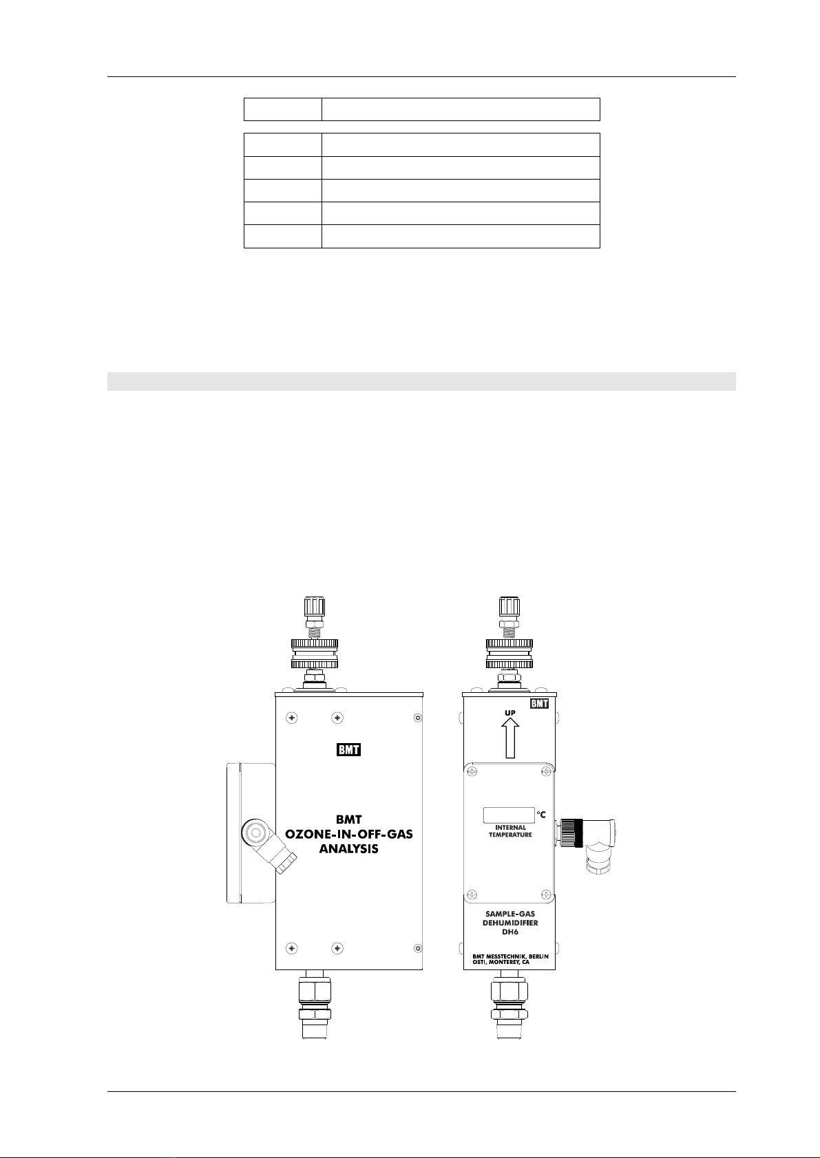
DH6 with SOBV (shut-off ball valve) DH6
SAMPLE GAS DEHUMIDIFIER DH6 Manual, Rev. 10/2020
4
MDH6EN-10-2020
The cooler/dryer DH6 (mounted at the point of sample) and the 24VDC/40W power supply are
connected with an electric cable. The maximal length of this cable may be 10 meters. An FEP
tubing 3x5 mm (optional Swagelok) is leading the sample gas from the DH6 to the ozone analys-
er (also available are fittings for 4x6 mm FEP tubing, and Swagelok 6 mm or ¼"). The dehumidi-
fied sample gas now will not form any condensate inside the sample tubing.
An optional Dirt Trap DT 100 can be provided in the tubing line for safety, and to watch the
sample gas after passage through the sample gas cooler/dryer.
2Cautions & Warnings
The exclamation point within an equilateral triangle is intended to alert the
user to the presence of important operating and maintenance (servicing) in-
structions in the literature accompanying the instrument.
Warning: Ozone is a highly toxic gas. The ozone concentrations fed through the SAMPLE GAS
DEHUMIDIFIER DH6 might be above the lethal limit. Appropriate safety devices (ozone mon-
itors) should be used.
Warning: Before opening the sample gas connections make sure that the sample line does not
contain ozone gas, and is not under pressure.
Caution: Before opening the lid of the electronics, the user should ground himself by touching
grounded points in order to prevent damage of the electronics by electrostatic discharge.
Précautions:
Avertissement
: L’ozone est un gaz à forte toxicité. Les concentrations d’ozone passant par le refroidisseur
/sécheur DH6 peuvent aller au-delà de la limite mortelle. C’est pourquoi
il convient d’utiliser une technique de sécurité adéquate (détecteur d’ozone).
Avertissement
: Avant d’ouvrir le circuit gaz, assurez-vous qu’il n’y a
pas de surpression dans la conduite du gaz à mesurer et qu’il n’y a pas
d’ozone dans le gaz.
Attention
: Avant d’enlever le couvercle du compartiment électronique,
reliez-vous à la terre en touchant une surface conductrice reliée à la terre
afin d'éviter d'endommager l’électronique par une décharge électrostatique.
3Installation
The DH6 removes water vapor from the sample gas. This re-
duction of the water vapor dew point obviously has to be per-
formed at the point of sample (e.g. on top of a reaction vessel,
or on a large diameter off-gas tube) to avoid condensate build-
up in the sample gas tubing leading from the sample point to
e.g. a photometric analyser. This patented principle allows for

SAMPLE GAS DEHUMIDIFIER DH6 Manual, Rev. 10/2020
5
MDH6EN-10-2020
any condensate to drop back into the reaction vessel.
If the dryer is located only just in front of the photometer, condensation of the water vapor takes
place in the sample gas tubing.
See our TechNotes TN-3 and TN-10
(www.bmt-berlin.de/technotes) for a detailed discussion.
Take care of the orientation of the dryer in order to let any condensate easily drop back into the
vessel or tube!
After power-up the LEDs "warm" and "max. power" are activated, until the desired internal
cooling temperature has been reached, see chapter 5 (Display) for details.
4Electrical connection
The pinout of the 4-pole electric connector is as follows:
black 1 GND (24VDC & cable shield)
white 2 +24 VDC (screw terminal
brown 3 contact DRYER ERROR side)
green 4 contact DRYER ERROR
The electronics are protected by a fuse rated 2A slow blow, type TR-5 (Wickmann). It also has a
reverse polarity protection, which will not burn the fuse in case of the wrong polarity. If connect-
ed to a BMT 964 OG off-gas analyser, no external power supply is needed.
5Display
The digital display shows the actual temperature of the inner wall of the cooler. After the user has
opened the lid of the display module using a screw driver (Pozidriv), a pushbutton switch and a
potentiometer are accessible.
Caution: Before opening the lid of the electronics box, the user should ground himself by touch-
ing grounded points in order to prevent damage by electrostatic discharge.
2
13
4

SAMPLE GAS DEHUMIDIFIER DH6 Manual, Rev. 10/2020
6
MDH6EN-10-2020
To adjust the set point temperature, the button has to be pressed. The display will show the set
point temperature, which now can be adjusted to a new value between 1ºC and 15°C in one de-
gree increments by turning the potentiometer with a small screw driver (supplied with the DH6).
Default setting is 5°C. The button has to be pressed and held all the time during setting the new
set point temperature. After releasing the button, the display will show the new set point temper-
ature flashing three times, and the parameter is saved.
Three LEDs on the digital display additionally are signaling the status as shown above.
The "warm" LED is activated if the set point temperature is exceeded by more than 1 K. The
Error relay is not activated. The LED is deactivated if the temperature reaches the set point tem-
perature (hysteresis of 1 K).
The "max. power" LED is activated upon maximum cooling power. This does not necessarily
mean any failure.
After power-on, both LEDs are activated for several minutes until the conditions for normal
operation are met.
In normal operation, all three LEDs are off, and the temperature inside the cooler is below the
set point plus 1 K. With increasing flow rate, temperature or dew point temperature of the sam-
ple gas, the cooler would increase the cooling power to compensate for the higher demand. If
any of the "warm" or "max. power" LEDs is on, the user should use the displayed temperature to
decide whether this still is well below the ambient temperatures around the gas path following the
dryer.
6Error Messages
The display shows several alphanumeric error messages:
SAMPLE GAS DEHUMIDIFIER DH6 Manual, Rev. 10/2020
7
MDH6EN-10-2020
message description
Err 1 temperature sensor defect (short or open)
Err 2 fan standstill
Err 3 no current flowing through Peltier block
Err 4 Peltier block shorted
Err 5 overtemp inside display module
In case any of the above errors the Peltier cooler and the fan are switched off. The error relay
opens. And the DRYER ERROR lamp in the front door of the BMT 965 OG is lit.
The error relay is also in it's error position while the power to the DH6 is switched off.
7Low Concentration Version DH6-LC
For measurement of very low concentration ozone, e.g. in humid vent gas behind an ozone de-
struct, the model DH6-LC is available. It has an inner PTFE lining, and a particle filter installed
at its outlet, assuring that the full length of tubing leading the sample gas to the ozone monitor is
protected against contamination by any particles contained in the sample gas.
The fitting at the outlet of the sample gas filter is accepting 1/4" (or 4x6 mm) FEP or PFA tub-
ing for direct connection to an OZONE MONITOR BMT 932.
SAMPLE GAS DEHUMIDIFIER DH6 Manual, Rev. 10/2020
8
MDH6EN-10-2020
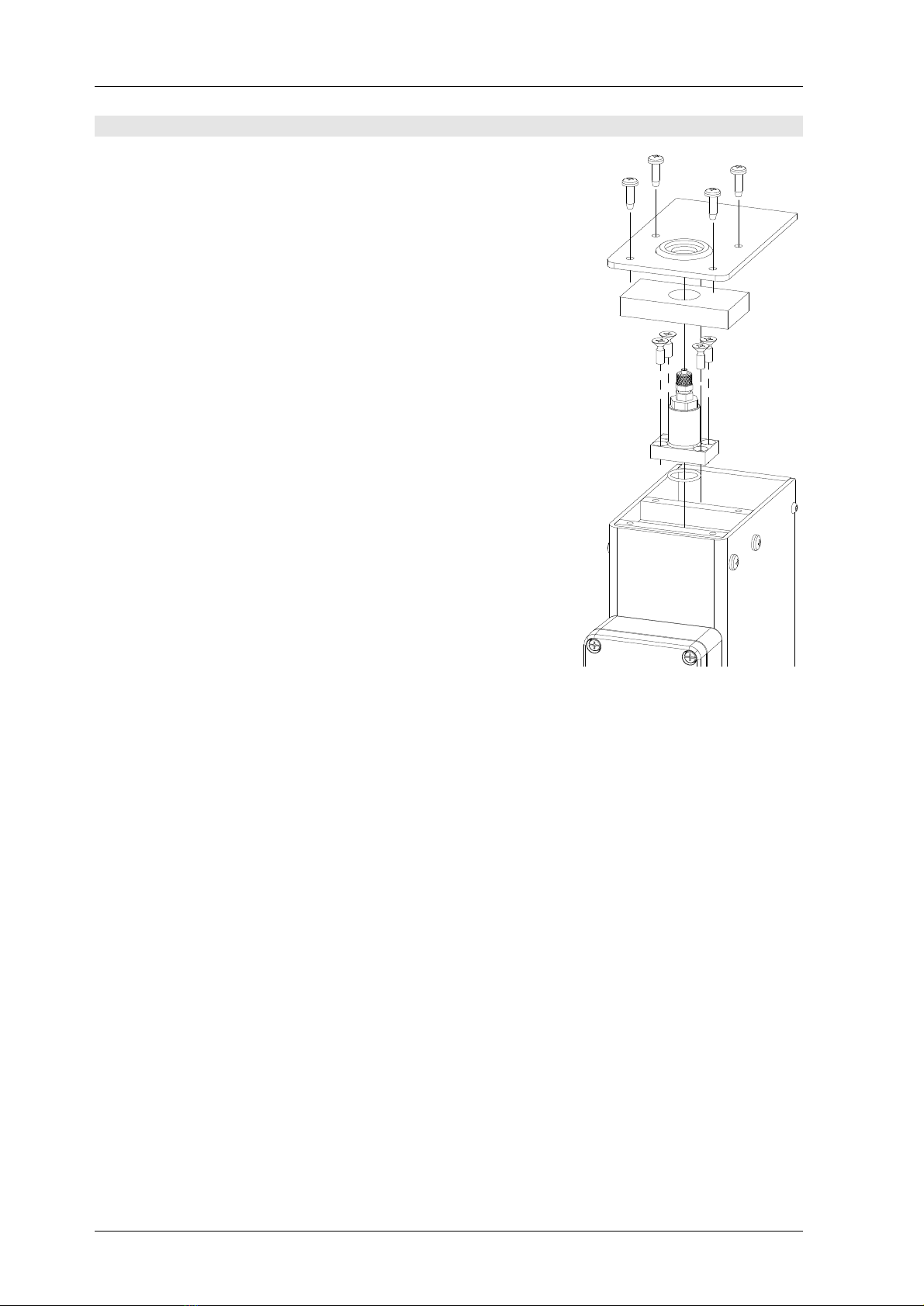
8Maintenance
The mechanical design of the dryer allows for cleaning of its gas
path. After disconnecting and removing the dryer from the sys-
tem, the top four screws need to be removed, which allows for
removing the top plate and the insulating material below.
Next, the four screws holding the fitting block must be removed,
followed by the fitting block itself. Note the O-ring at the bottom
of the fitting block.
The inner side of the cooling tube may now be cleaned by using a
bottle brush or similar – the smallest diameter of the tube at the
bottom is 9 mm. Have a look at the inside of the fitting and the
SOBV (if ordered) as well. Avoid the spilling of fluids outside of
the gas path.
Before re-assembling the dryer, thoroughly inspect the O-ring. A
damaged O-ring may not be used again.
Re-assembly of the DH6 must be done in reverse order, followed
by a leak test. Further maintenance is not necessary.
BMT Messtechnik GmbH +49-3329-69677-0
D-14532 Stahnsdorf
Germany
or for North America, Central America, Pacific Rim:
OSTI Inc. +1-831-649-1141
Colorado Springs
CO 80907, USA
Please contact us before sending any equipment in for service.

SAMPLE GAS DEHUMIDIFIER DH6 Manual, Rev. 10/2020
9
MDH6EN-10-2020
9Specifications
principle Peltier-electric cooling system, no moving parts
flow rate 0.3 to 0.5 l/min
MTBF 40.000 h (fan)
proof pressure min 1 bar gauge
pressure drop 0.1 mbar @ 0.5 l/min; DH6-LC with filter: approx. 6 mbar @ 0.5 l/min
ambient temperature 0 - 40°C (non-condensing)
cooling power 4.5 W @ ΔT (Tambient – Tset) = 20 K
power-on to operational max 10 minutes @ ΔT (Tambient – Tset) = 20 K and recommended flow rate
materials in contact SS, PTFE, PVDF
inlet gas port tube with OD 12 mm, 3/8" NPT thread, with PTFE seals
outlet gas port for FEP tubing 3 x 5 mm (1/8" x 3/16"),
or for FEP tubing 4x6 mm (1/4" x 5/32")
or Swagelok 6 mm or ¼"
display 4 digits LED
power 24 VDC, 40 W (via separate power supply), reverse polarity protected
relay outputs 60 V, 1 A
dimensions (W x H x D) 64 x 279 x 140 mm
weight 1.5 kg
protection IP 55 (including fan)
Table of contents
Popular Dehumidifier manuals by other brands


Honeywell
Honeywell TrueDRY DR90 quick start guide

Olimpia splendid
Olimpia splendid AQUARIA 18 P Instructions for installation, use and maintenance

Breville
Breville Smart Dry Ultimate LAD500 Instruction book

Clarke
Clarke YDK10 Operation & maintenance instructions

Carrier
Carrier CDF-20Q7 owner's manual

Ruby
Ruby DN 12 EN instruction manual


