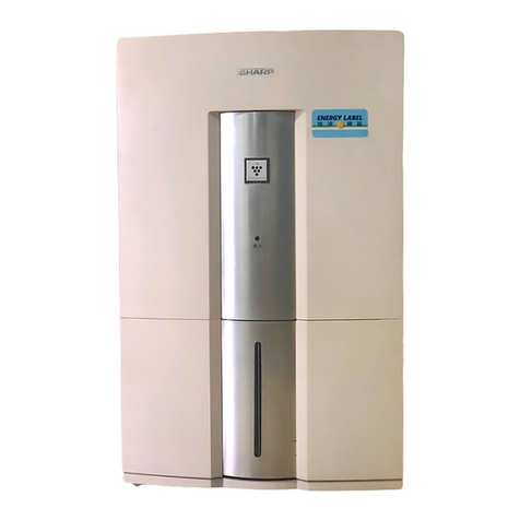
Sharp DW-71-H User manual

1
DW-71-H
SY657DW71HH//
SERVICE MANUAL
SHARP CORPORATION
Page
PRECAUTION....................................................................................................................................................... 2
SPECIFICATION................................................................................................................................................... 6
PRINCIPLE OF DEHUMIDIFING FUNCTION...................................................................................................... 7
NAMES AND FUNCTIONS OF PARTS ............................................................................................................... 8
EXPLANATION OF FUNCTION........................................................................................................................... 9
DISASSEMBLING AND REPLACEMENT OF MAIN PARTS............................................................................. 12
CIRCUIT DIAGRAM AND EXPLANATION OF OPERATION ............................................................................ 17
TROUBLESHOOTING AND CORRECTIVE ACTIONS ...................................................................................... 21
LIST OF TROUBLES AND CORRECTIVE ACTIONS......................................................................................... 22
ADAPTATION TO '96 CHLOROFLUOROCARBON REGULATIONS.................................................................25
HFC-134a CYCLE REPAIR PROCEDURE......................................................................................................... 26
PACKING .............................................................................................................................................................34
REPLACEMENT PARTS LIST ............................................................................................................................ 35
TABLE OF CONTENTS
Intheinterestsofuser-safety(Requiredbysafetyregulationsinsome
countries)thesetshouldberestored to its originalconditionandonly
parts identical to those specified should be used.
DW-71-H
MODEL
DEHUMIDIFIER

2
DW-71-H
PRECAUTION
Caution symbols
Symbols are used throughout this manual to indicate the effects of negligence and improper
use. Please pay attention and read this section carefully.
Warning
Negligence could result in death or serious injures.
Attention
Negligence could result in serious injuries or loss of properties
Meaning of the
symbols EXTRA CAUTION needed.
Actions not allowed to take.
Actions that you have to take.
Keep this handy and make sure to read the safety precaution before using the dehumidifier.
When installing Attention
Important
Do not operate the unit in a closet or in a narrow space
between furniture.
Insufficient ventilation can result in overheating or combustion.
Do not install the unit at locations where it is exposed to water splashes.
This can cause electric shock or fire.
Do not install the unit at locations where oil or combustible gas leakage can
occur.
Leaked oil or gas near the unit can cause fire.
Donotputavesselcontainingwatersuchasvaseontheunit.
Dripped water on the unit can lower the rate of electric insulation,
resulting in electric shock, electrical leakage or fire.
This unit is for in-door use only. Do not install it at locations
where it is exposed to direct sunlight, rain or wind.
This can cause overheating, electric shock, electrical leakage or fire.
Do not use this unit for storage of things that require strict temperature control
such as art works or academic materials.
This can lower the quality of the stored items.
Should the supply cord be damaged, it must be replaced by
a service center approved by Sharp as special tool are
required.
This equipment complies with the requirements of
Directives 89/336/EEC and 73/23/EEC as amended by 93/
68/EEC.

3
DW-71-H
Note
Make sure that the unit is operated on a flat and solid surface.
Uneven surface can cause spilling of the stored water and wet other household furnitures or
appliances and cause electric shock, electrical leakage or fire.
During continuous drainage, make sure that the hose is not bent and the hose
outlet is laid down properly.
Otherwise the drained water might spill and wet household appliances.
Lay the hose
on a down
slope. 10 cm or more
Do not bend the
drain hose. Do not put the
open end of
the drain hose
in water.
Attention
When a draining hose is to be used, make sure that the temperature around the
hose is above 0°C. Otherwise water in the hose might freeze and undrained
water might spill in the room.
When operating
Warning
Important
Do not stick your finger or any object into the air outlets
or intake.
The rotating internal fan can cause injuries.
Do not operate the unit with voltages other than the
rated voltage of 230V.
This can result in electric shock or fire.
Do not use an extension power supply cord or share the socket with other
electrical appliances.
This can cause electric shock, overheating or fire.
Avoid damaging the power supply cord or modifying it on your own.
This can cause electric shock or fire.
Laying heavy objects, nipping, heating or pulling can damage the cord.
Do not start or stop the operation by inserting or pulling out the
plug from the socket.
This can cause electric shock or fire.
Avoid heating sources
Do not place the unit near heating sources.
Resin parts of the unit might melt and catch fire.

4
DW-71-H
Note
After making sure that the power supply plug is not covered with dust, insert
the plug into the socket firmly.
When there is dust or the connection is improper, electric shock or fire might be resulted.
Attention
Important
Do not obstruct the air outlets and air intake.
This can prevent the air from passing and result in
overheating or fire. 5 cm or more
Do not stand or sit on the unit.
Injury can be resulted if you fall down or the unit topples.
Do not wash the unit directly with water.
This can result in electric shock.
Do not place the unit near combustible equipment or under direct sunlight.
This can affect the combustible performance of the equipment.
Do not unplug by pulling the cord, pull the plug.
Pulling the cord can cause the wire to break and result in overheating or fire.

5
DW-71-H
Note
Make sure to turn off the power and unplug the unit
before carrying out maintenance.
The rapidly rotating internal fan can cause injuries.
Before moving the unit make sure that the power is
turned off and the water is drained from the tank.
Spilled water might wet household appliances and cause
electric shock or fire.
Unplug from the socket.
If the unit is not to be used for a long period, please
unplug the unit for safety purpose.
Otherwise this might be resulted in electric shock or fire.
Repair
Warning
Do not disassemble the dehumidifier.
Do not modify the unit.
This can cause fire, electric shock or injuries.
This unit should not be disassembled or repaired
by persons other than qualified technician.
Otherwise this might be resulted in fire, electric shock or
injuries.
Unplug from the socket.
When any abnormality (for example, burning smell) is found, turn the power off,
unplug the unit and consult your dealer.
If the unit is operated despite the abnormal state, a breakdown, electric shock or fire can be
resulted.
If the unit is used in the absence of any person for a
long period, make sure that reqular inspection will be
made.
Otherwise overheating or electrical leakage might be resulted.

6
DW-71-H
Thepowerconsumptionshown above is data obtainedinconditionofroomtemperature (27˚C) and relative humidity
60%.
The dehumidification enable area is based on JIS.
The power comsumption in stand by model is measured in the sate where the power plug is inserted into the socket.
Noise data
Operating state Noise
Dehumidifying Approx. 37 dB
Drying Clothes Approx. 38 dB
Model
Rated dehumidifying capacity
Rated voltage
Rated frequency
Power Rated current
consumption Dehumidifying mode
Drying Clothes mode
Compressor
Cooler
Condenser
Defrosting system
Fan
Fan motor
Water tank
Defrosting Defrosting timer
Defroster thermo-switch
Power switch
Operation mode selection switch
FULL switch
Indication system
Filter
Discharge water elbow
Overall size
Weight
Power supply cord
Dehumidification enable area
Refrigerant
SPECIFICATION
DW-71-H
6.3 L/day (daily dehumidifying capacity in conditions of room temperature
27˚C and relative humidity 60%)
230V
50Hz
1.0A
187W
190W
Rorary compressor, output 100W (model XB357RCA)
Plate type with forced draft
Hot gas defrosting
ø160 sirocco fan
Shading Coil type single-phase induction motor (2-Pole, output 3W, with temperature fuse)
Automatic stop when about 3 liters is stored. (capacity about 3.8 liters)
Timer IC (period about 40 min)
Thermistor detection
Push switch
Push switch
Microswitch (model V-55100)
Dehumidifying / Drying Clothes lamp: Green
Defrosting lamp: Green
FULL lamp: Orange
Front filter, Air clean filter
Made of resin (to be used for continuous water discharge)
370 mm (W) x 210 mm (D) x 485 mm (H)
Approx. 9.6 kg
Effective length: Approx. 1.8 meters
13 to 20 m2
HFC-134a, 140g

7
DW-71-H
PRINCIPLE OF DEHUMIDIFING FUNCTION
(Wet air)
Eevaporator : The evaporator the vapor contained in the indoor air and condensate it to trap.
Condenser: The condenser heats the air cooled by the cooler.
Fan: The fan sucks in the wet air, and discharges the dry air sent from the condenser into the inddor space.
(Dry air)
Notes
Unlike the air conditioner, the drying and dehumidifying machine does not have cooling function.
As the unit produces some heat during operation, your room temperature may increase by about 2 - 5˚C
depending upon the operating conditions (outside temperature,room size).
As the drying and dehumidifying machine is used in closed room, the room temperature rises in the summer.
Even when the drying and dehumidifying machine is used, the humidity lower than approx. 50% cannot be
maintained. There is no possibility, however, of excessive drying.
Principle of dehumidifying function
In the summer we see dews on the surface of glass cup filled with cool water or on the window glass of heated room in the
winter. Dews appear due to condensation of moisture contained in the air as a result of cooling of hot air by cool air.
This phenomenon is applied in the machine.

8
DW-71-H
NAMES AND FUNCTIONS OF PARTS
ON / OFF
DRYING CLOTHESDEHUMIDIFYINGDEFROSTINGWATER TANK FULL OPERATION SELECTION
FULL
Front View
Air intake
Front
door
Front filter
Water tank
where water is stored.
Full line indicator
When the water level reaches this
line, the operation stops
automatically.
Rear View
Lever
Used for changing the
airflow direction
Airflow outlet
(upward/diagonally
downward direction)
Continuous
drainage hole
Used for draining water
continuously
Power supply
cord
Carrying handle
Pull out the handle when
moving the unit.
Carrying handle
Cord clamp
Plug
Control Panel
FULL lamp
Lights when the water tank is full.
DEFROSTING lamp
Lights when defrosting is carried out.
DEHUMIDIFYING lamp
Lights during dehumidifying operation
DRYING CLOTHES indicator lamp
Lights during drying clothes operation.
Operation selection button
Alternatively carry out dehumidifying and drying clothes
operations.
Power ON/OFF button
Turns the power on and off.

9
DW-71-H
EXPLANATION OF FUNCTION
1. Operation modes
(1) Dehumidifying mode
(2) Drying clothes mode
Operation procedure
1.Insert the power plug into the socket.
2. Ascertain that the water tank has been installed correctly.
3. Press the power ON/OFF button.
4. Choose the proper operation mode with the operation mode selection button.
(Whenever the operation mode selection button is pressed, the DEHUMIDIFYING mode and the DRYING
CLOTHES mode are alternately selected.)
Dehumidifying mode
Dehumidifying capacity diagram
Testing conditions: Relative humidity 60%.
The dehumidifying capacity varies depending on ambient
temperature and relative humidity.
The graph shows the dehumidifying capacity at specified
temperature and humidity.
1. Dehumidifying mode
The fan motor runs slowly and continuously.
2. Drying clothes mode
The fan motor runs continuously with high speed (air flow
rate is increased by 20%).
The fan sucks
the wet air into
the dehumidifier.
The air is cooled by the
cooler, and the water
vapor is condensed.
Dews on the cooler flow
down from the dew pan
into the water tank.
The dehumidified air is
heated by the condense
and discharged out.
•This process is repeated continuously, resulting in reduction of indoor
humidity.
•When the discharge tank is filled fully with water, the FULL WATER
STOPPER is actuated, the FULL lamp lights, and the machine is stopped.
0 5 10 15 20 25 30
1
2
3
4 60Hz
5
6
7
8
When humidity is 60%
Room temperature
Dehumidittying capacccity (L/day)
(˚C)

10
DW-71-H
2. Changing the airflow direction
3. Defrosting mode
(1) Necessity of defrosting
Whentheroom temperature lowers belowapprox.16:, the temperature ofcoolerlowers below 0 :,resultinginfrosting
of cooler which impedes air flow. Therefore defrosting must be performed timely.
(2) Start of defrosting
When the defrosting thermistor temperature sensor detects temperature of about 2.5 : or below and the IC timer
counts approx. 40 min., while the room temperature is below approx. 16 :, the defrosting operation is started.
(3) End of defrosting
When the defrosting thermistor temperature sensor detects about 12 :, the defrosting is ended, and the normal
operation is resumed.
The defrosting time is about 5 to 10 minutes.
(4) Hot gas defrosting system
In the defrosting mode the solenoid valve is actuated and opened, so that the hot gas flows in the arrow direction
shown in the figure to remove the frost on the cooler.
In the defrosting mode the solenoid valve is actuated and
opened, so that the hot gas flows in the arrow direction
shown in the figure to remove the frost on the cooler.
Upward
Diagonally downward
Push the lever upward.
To dehumidify your room
To dry clothes
Perform the
drying clothes
operation.
Push the lever downward.
Open the door
of the closet
and operate the
unit in front of it.
To dehumidify a closet or wall
Cooler
Capillary
Dryer filter Condenser
Compressor
Solenoid valve

11
DW-71-H
4. Continuous drainage
1
2
3
4
1
2
3
4
You can continuously drain the water from the unit with the use of the right
draining facilities. Make sure to turn off and unplug the unit before carrying out
the following procedures.
Punch out the continuous
drainage hole.
Insert the drain hose elbow
into the hose and pass the
hose through the hole.
Push the drain hose elbow
into the unit.
Return the water tank.
Open the front door and
let the open end of the
hose pass through the
hole.
Remove the water tank and punch out the
continuous drainage hole on the back of
the unit using a screwdriver and finish the
edge with a knife. Continuous draining hole
A commercially
available hose with a
15 mm inside diameter
10 mm or more
Drain hose elbow
Push the drain hose elbow into the draining
section of the unit until you hear a click.
Drain hose
elbow
The unit will not operate unless the tank has
been returned and properly positioned.
Water tank

12
DW-71-H
DISASSEMBLING AND REPLACEMENT OF MAIN PARTS
(*Assemblethepartsinthereverseorderof disassembling)
Before disassembling
Remove the filter frame and the water tank.
1. Removing the handle
(1) Withdraw the handle from the main unit, remove
the flat countersunk head screw at the lest side,
and remove the handle stopper.
(2) Turnthe released side ofhandle by 90˚C toremove
the handle from the square hole of main unit.
2. Removing the rear part of main unit
(1) *Remove the screws (2 pcs.) at the rear upper side
of main unit. [Screw A]
(2) Remove four screws on the rear of main body.
[Screw B]
(Twoscrewsonthebottomofmainbodyarelonger.)
(3) Remove one screw at the center on the rear of main
body. [Screw C]
Use the special screwdriver which matches the
shape of the screw head as shown in the drawing.
(The special screwdriver is used as a
countermeasure to make the qualified engineer of
the manufacturer or its representative replace the
power cable if it is broken.)
Part code for request of special screwdriver
UKOG-A001FBE0 ; Special screw
Handle
Filter frame
Water tank
Front cover
Handle
Handle stopper
Screw
1
2
Main unit rear part
(4) Withdraw the main unit rear part to this side.
Screw A
Screw C
(Special screw) Screw B

13
DW-71-H
3. Removing the main unit front part
(1) Remove the casing SK fixing screws (2 pcs.).
(Handle reinforcement angle fixing screws)
(2) Widen outward the lower parts of main unit front
part, and withdraw to this side.
(3) Remove the power supply cover inside the evaporator
top box.
(4) Holding the power supply PWB, withdraw the harness
of operation section.
Main parts
(2) Release the harness from the casing.
(3) Remove the screws fixing the casing to the main unit.
4. Removing the fan motor
(If the fan motor failed to run, be sure to replace the fan
together with the fan motor.)
(The fan vibrates more remarkably, causing growing
noise.)
After removing the front and rear parts of main unit
(1) Disconnect the connector of power supply PWB.
Screw
Casing
Display PWB harness
Power supply PWB
For fan motor
Harness
fixing rib
Fan fixing
screw Screw
Casing
ScrewScrew
Transfomer cover (The transformer is under the cover)
Power supply cover
Earth terminal
Dew pan
Magnetic coil
Dryer
Filter
Suction pipe ass'y
Butyl rubber
Bottom plate
ass'y
Power supply PWB Evaporator top box
Evaporator
Fin cover
Fan motor
Casing
Capacitor
Compressor
FULL switch
Sirocco fan

14
DW-71-H
(3) Remove the PWB fixing screws (2 pcs.).
6. Removing the operation PWB
(1) After removing the front part of main unit remove
the switch box fixing screws (3 pcs.).
(2) Shiftthe switch boxtoward the screws, and remove
it from the rib of front part of main unit.
(4) Remove the screw (1 pc.) fixing the fan.
(5) Remove the harness (positive rack).
(6) Remove the screws (2 pcs.) fixing the motor.
5. Removing the power supply PWB
(1) Remove the power supply cover fixing screws (after
removing one screw, shift the cover to the right,
andthenremovetheremaining screws(arrowmark,
Figure 4-2 below)).
(2) Remove the connector.
Screw
Up
Screw
To the right
Screw Front part of main unit
Switch box
Red(Low)
Screw
Orange(High)
(Upper)
Gray(Com)
(Lower)
For compressor cord
For defrosting lamp For magnetic coil
For control
For fan motor
For power
switch
For power cord
Waterproof rubber
Waterproof rubber
Switch box Button B
(for selection) Button A
(for power supply)
(3) Remove the ribs (2 pcs.) with which the operation
PWB is engaged.
7. Removing the capacitor
(1) Remove the rear part of main unit.
(2) Straighten the pawl of dew pan which fixes the
capacitor, lift the capacitor and remove it.
Power switch
Selection switch
Operation PWB

15
DW-71-H
9. Removing the protector
(1) After removing the rear part of main unit, widen the
fixtureofupperpart of compressor, andremovethe
terminal cover.
Connection of compressor cord ass'y
8. Removing the FULL switch
(1) After removing the rear part of main unit disengage
the rib of dew pan with which the switch holder is
engaged, and withdraw the switch holder.
FULL switch ass'y
Switch holder
Rib
Fixture
Terminal cover
CN-B
1
IS-187
(natural color)
Shinagawa Shoko
Purple
Red
I
S-187 (natural color)
Shinagawa Shoko To FULL switch
IS-187 (natural color)
Shinagawa Shoko
To FULL switch
Orange
Capacitor
(4µF, 430VAC)
Red
Orange
Blue
Gray
Insert into hole
and solder.
Protector
With tube
With sleeve

16
DW-71-H
10. Removing the damper (for air direction change)
After removing the rear part of main unit remove the
screws (2 pcs.) fixing the damper support.
13.Removing the water tank handle and float
(1) Fit the protrusion of handle to the dent of water
tank, and tilt the handle inward to withdraw it.
(2) Widen the water tank, release the protrusion of
float, and remove the float. (Be sure to hold the
flout horizontally. Fit the lower resting part of float
to the supporting part of water tank.)
12. Removing the magnetic coil
Removing the front and rear parts of main unit
(1) Remove the hex screw fixing the magnetic coil with
pliers.
(2) Remove the power supply cover, and remove the
connector.
Installing the float
Insert the float into the hole (1) as shown in the
figure, put the float flange on the protrusion (2) of
water tank, and insert the opposite side into the
hole (3).
Be sure to ascertain that the float flange lies on the
protrusion of water tank. Unless it lies on the
protrusion, operation is disabled.
14. Removing the transformer
(1) Remove the front and rear parts of main unit.
(2) Remove the power supply cover.
(3) Remove the screws (2 pcs.) fixing the transformer
cover.
(4) Disconnect the connector of power supply PWB.
11. Removing the defrosting thermistor
Removing the front and rear parts of main unit
(1) Fit the front end of slotted head screwdriver into the
root of shaped tube into which the thermistor
has been mounted, and widen it to remove the
thermistor.
(After replacing tighten the root with pliers.)
(2) Remove the power supply cover, and remove the
connector.
Rear part of main unit
Screw (2 pcs.)
Damper supportDamper
1
2
3
Protrusion of water tank
Handle
Screw
Up
Screw
Transformer
cover
Transformer
mounting screw
Transformer
Earth terminal
screw
To the right
Hex screw
Solenoid coil
Insertion tube
(glasses-shaped)
Thermistor

17
DW-71-H
CIRCUIT DIAGRAM AND EXPLANATION OF OPERATION
Circuit diagram

18
DW-71-H

19
DW-71-H
1. Explanation of operation
Operation mode
(1) When the START button is pressed, power supply for the compressor and fan motor is turned on, and
the dehumidification operation is started.
Using the operation selection button, select the dehumidification operation or the drying clothes operation.
1) Dehumidification operation
RY1: OFF, RY2: OFF (fan motor slow run), Dehumidification lamp :ON
2) Drying clothes operation
RY1: OFF, RY2: ON (fan motor high speed run), Drying clothes lamp: ON
(2) Defrosting operation
1) Defrosting start
When the room temperature is lower than 16˚C or the humidity is low, the defrosting thermistor senses
2.5˚C or below.
If the defrosting thermistor senses 2.5˚C or below while the compressor is on and 40 minutes or more
elapse, the defrosting operation is started.
2) Defrosting operation
RY1: ON, RY 2: OFF (Fan motor stop, Solenoid valve: ON)
Defrosting lamp: ON
3) End of defrosting
When the defrosting thermistor detects temperature 12˚C or above, the defrosting is aborted, and the
regular operation is restored.
(3) Water fullness detection
When the water tank is filled fully with water or the tank has not been installed correctly, the water fullness
state is set.
The compressor, fan motor and solenoid valve are stopped, and the FULL lamp lights.
When the water fullness state is cancelled, the operation mode preceding to the water fullness state is
resumed. (The defrosting operation is also discontinued.)
(4) Test mode
The test mode is used to inspect the PWB assembly
and product after repair.
1) Quick defrosting
When the jumper lead “QUICK
DEFROSTING” of power supply PWB is short
-circuited, the defrosting detecting timer setting
is reduced from approx. 40 min to approx.
4 seconds. Accordingly, if the jumper lead is
short-circuited when the defrosting thermistor
senses 2.5˚C or below, the defrosting operation
is started after 4 seconds.
2) Forced defrosting
When the jumper lead “FORCED DEFROSTING”
of operation PWB is short-circuited, the forced defrosting is started. (RY1: ON, RY 2: OFF, DEFRO
-STING lamp: ON)
Visible from switch box
3) Inspection procedure
For short-circuiting of jumper lead, use the tip of screwdriver or banana clip.
Quick defrosting
(Jamper wire)

20
DW-71-H
3. Location of PWB parts
(1) Power supply PWB
Parts side
(2) Operation PWB
Parts side
Table of contents
Other Sharp Dehumidifier manuals

Sharp
Sharp DW-J27A User manual

Sharp
Sharp DW-208EX User manual

Sharp
Sharp DW-E16FA-W User manual

Sharp
Sharp DW-D20A User manual

Sharp
Sharp DW-D12A User manual

Sharp
Sharp DW-E16FA User manual

Sharp
Sharp DW-P22A User manual

Sharp
Sharp DW-RN23A-W User manual

Sharp
Sharp UD-P16E-W User manual

Sharp
Sharp DW-J27FA User manual
Popular Dehumidifier manuals by other brands

Emelson
Emelson DFR29 owner's manual

Teddington
Teddington Seco+ Installation and user manual

Ruby
Ruby DN 35-RE manual

Meaco
Meaco 10L small home dehumidifier instruction manual

Argo
Argo NARCISO baby 10 instruction manual

Innovative Dehumidifier Systems
Innovative Dehumidifier Systems IW-25-2 Installation and operation manual