BMW E90 User manual

Initial Print Date: 03/05
Table of Contents
Subject Page
Introduction . . . . . . . . . . . . . . . . . . . . . . . . . . . . . . . . . . . . . . . . . . . . . . . . . .8
Primary Control Modules . . . . . . . . . . . . . . . . . . . . . . . . . . . . . . . . . . . . . . .10
Functions of Junction Box Electronics Control Module . . . . . . . . . .10
Functions of Footwell Module . . . . . . . . . . . . . . . . . . . . . . . . . . . . . . . .12
Functions of Roof Function Center . . . . . . . . . . . . . . . . . . . . . . . . . . . .13
Functions of Car Access System . . . . . . . . . . . . . . . . . . . . . . . . . . . . .14
Car Access System 2 - Input/Output . . . . . . . . . . . . . . . . . . . . . . . . . . . .16
Car Access System 2 - Circuit Diagram . . . . . . . . . . . . . . . . . . . . . . . . . .18
Central Locking . . . . . . . . . . . . . . . . . . . . . . . . . . . . . . . . . . . . . . . . . . . . . .20
Control Modules for Central Locking Function . . . . . . . . . . . . . . . . . . . .20
Car Access System 2 (CAS2) . . . . . . . . . . . . . . . . . . . . . . . . . . . . . . . .21
Footwell Module (FRM) . . . . . . . . . . . . . . . . . . . . . . . . . . . . . . . . . . . . . .21
Unlocking/Locking the Vehicle . . . . . . . . . . . . . . . . . . . . . . . . . . . . . . . . . .22
Unlocking Procedure . . . . . . . . . . . . . . . . . . . . . . . . . . . . . . . . . . . . . . . .23
Locking Procedure . . . . . . . . . . . . . . . . . . . . . . . . . . . . . . . . . . . . . . . . . .23
Using Identification Transmitter . . . . . . . . . . . . . . . . . . . . . . . . . . . . . . .23
Center-Lock Button . . . . . . . . . . . . . . . . . . . . . . . . . . . . . . . . . . . . . . . . .23
Mechanical Key/Spare Key . . . . . . . . . . . . . . . . . . . . . . . . . . . . . . . . . . .23
Locking Button on Vehicle Doors . . . . . . . . . . . . . . . . . . . . . . . . . . . . .24
Opening the Trunk Lid . . . . . . . . . . . . . . . . . . . . . . . . . . . . . . . . . . . . . . . . .24
Opening with Remote Control/Identification Transmitter . . . . . . . . .24
Opening with the Outer Trunk Lid Button . . . . . . . . . . . . . . . . . . . . . .24
Opening with the Inner Trunk Lid Button . . . . . . . . . . . . . . . . . . . . . . .24
Special Functions . . . . . . . . . . . . . . . . . . . . . . . . . . . . . . . . . . . . . . . . . . . . .25
Automatic Locking (Personal Profile) . . . . . . . . . . . . . . . . . . . . . . . . . .25
Selective Unlocking . . . . . . . . . . . . . . . . . . . . . . . . . . . . . . . . . . . . . . . . .25
Unlocking After an Accident . . . . . . . . . . . . . . . . . . . . . . . . . . . . . . . . . .25
Location of Control Modules . . . . . . . . . . . . . . . . . . . . . . . . . . . . . . . . . . . .26
Footwell Module (FRM) . . . . . . . . . . . . . . . . . . . . . . . . . . . . . . . . . . . . . .26
Car Access System 2 (CAS2) . . . . . . . . . . . . . . . . . . . . . . . . . . . . . . . .26
Junction Box Electronics Control Module (JBE) . . . . . . . . . . . . . . . .26
Components of Central Locking System . . . . . . . . . . . . . . . . . . . . . . . . .27
Controls . . . . . . . . . . . . . . . . . . . . . . . . . . . . . . . . . . . . . . . . . . . . . . . . . . .27
Remote Control . . . . . . . . . . . . . . . . . . . . . . . . . . . . . . . . . . . . . . . . .27
Center-Lock Button . . . . . . . . . . . . . . . . . . . . . . . . . . . . . . . . . . . . . .28
Driver's Door Lock Barrel . . . . . . . . . . . . . . . . . . . . . . . . . . . . . . . . .28
E90 General Vehicle Electrical
Revision Date: 04/05

Subject Page
Central Locking Drive Units . . . . . . . . . . . . . . . . . . . . . . . . . . . . . . . . . .28
Central Locking Drive Units in the Doors . . . . . . . . . . . . . . . . . . .28
Central Locking Drive Units for Truck Lid and Fuel Filler Flap . .29
Manually Release for Fuel Filler Flap . . . . . . . . . . . . . . . . . . . . . . .29
Lock Barrel, Trunk Lid . . . . . . . . . . . . . . . . . . . . . . . . . . . . . . . . . . . .29
Emergency Trunk Lid Release . . . . . . . . . . . . . . . . . . . . . . . . . . . . .29
Central Locking - Inputs/Outputs . . . . . . . . . . . . . . . . . . . . . . . . . . . . . . . .30
Central Locking - Circuit Diagram . . . . . . . . . . . . . . . . . . . . . . . . . . . . . . .32
Comfort Access . . . . . . . . . . . . . . . . . . . . . . . . . . . . . . . . . . . . . . . . . . . . . .35
Control Modules for Comfort Access Function . . . . . . . . . . . . . . . . . . . .36
Car Access System 2 (CAS2) . . . . . . . . . . . . . . . . . . . . . . . . . . . . . . . .36
Junction Box Electronics Control Module (JBE) . . . . . . . . . . . . . . . .36
Footwell Module (FRM) . . . . . . . . . . . . . . . . . . . . . . . . . . . . . . . . . . . . . .36
Electronic Outer Door Handle Module (TAGE) . . . . . . . . . . . . . . . . . .37
Functions of Comfort Access . . . . . . . . . . . . . . . . . . . . . . . . . . . . . . . . . . .37
Passive Entry . . . . . . . . . . . . . . . . . . . . . . . . . . . . . . . . . . . . . . . . . . . . . . .38
Unlocking . . . . . . . . . . . . . . . . . . . . . . . . . . . . . . . . . . . . . . . . . . . . . . .38
Opening Trunk Lid . . . . . . . . . . . . . . . . . . . . . . . . . . . . . . . . . . . . . . .38
Passive Go . . . . . . . . . . . . . . . . . . . . . . . . . . . . . . . . . . . . . . . . . . . . . . . . .38
Issuing Start Enable . . . . . . . . . . . . . . . . . . . . . . . . . . . . . . . . . . . . . .38
Passive Exit . . . . . . . . . . . . . . . . . . . . . . . . . . . . . . . . . . . . . . . . . . . . . . . .39
Locking Procedure . . . . . . . . . . . . . . . . . . . . . . . . . . . . . . . . . . . . . . .39
Special Comfort Access Functions . . . . . . . . . . . . . . . . . . . . . . . . . . . .40
ID Transmitters Remain in Vehicle . . . . . . . . . . . . . . . . . . . . . . . . . .40
ID Transmitter Remains in Trunk . . . . . . . . . . . . . . . . . . . . . . . . . . .40
Engine Start Disable . . . . . . . . . . . . . . . . . . . . . . . . . . . . . . . . . . . . .40
Starting Engine without ID Transmitter . . . . . . . . . . . . . . . . . . . . .41
Check Control Message, Terminal 15 . . . . . . . . . . . . . . . . . . . . . .41
Unintentional Wake-up Function . . . . . . . . . . . . . . . . . . . . . . . . . . .41
Locking with Engine Running . . . . . . . . . . . . . . . . . . . . . . . . . . . . .41
Components of Comfort Access System . . . . . . . . . . . . . . . . . . . . . . . . .42
Comfort Access Control Module . . . . . . . . . . . . . . . . . . . . . . . . . . . . . .42
Identification Transmitter . . . . . . . . . . . . . . . . . . . . . . . . . . . . . . . . . . . . .43
Voltage Monitoring . . . . . . . . . . . . . . . . . . . . . . . . . . . . . . . . . . . . . . . . . .43
Antennas for Comfort Access . . . . . . . . . . . . . . . . . . . . . . . . . . . . . . . .44
Locations of Exterior Antennas . . . . . . . . . . . . . . . . . . . . . . . . . . . .44
Locations of Interior Antennas . . . . . . . . . . . . . . . . . . . . . . . . . . . . .44
Antenna in Outer Door Handles . . . . . . . . . . . . . . . . . . . . . . . . . . .45
Antenna in Bumper . . . . . . . . . . . . . . . . . . . . . . . . . . . . . . . . . . . . . .45
Antennas for the Passenger Compartment . . . . . . . . . . . . . . . . . .45
Antenna for Luggage Compartment . . . . . . . . . . . . . . . . . . . . . . . .45
Electronic Outer Door Handle Module (TAGE) . . . . . . . . . . . . . . . . . . . .46
Design . . . . . . . . . . . . . . . . . . . . . . . . . . . . . . . . . . . . . . . . . . . . . . . . . . . . .46

Subject Page
Sensors . . . . . . . . . . . . . . . . . . . . . . . . . . . . . . . . . . . . . . . . . . . . . . . . . . .47
Functional Principle of the Capacitive Sensor . . . . . . . . . . . . . . . . . .47
Capacitive Sensor 1 . . . . . . . . . . . . . . . . . . . . . . . . . . . . . . . . . . . . . . . . .47
Capacitive Sensor 2 . . . . . . . . . . . . . . . . . . . . . . . . . . . . . . . . . . . . . . . . .48
Hall Sensor of the Outer Door Handle . . . . . . . . . . . . . . . . . . . . . . . . .48
Lock in Driver's Door & Front Passenger's Door . . . . . . . . . . . . . . . . . . .49
Comfort Access - Input/Output . . . . . . . . . . . . . . . . . . . . . . . . . . . . . . . . .50
Comfort Access - Circuit Diagram . . . . . . . . . . . . . . . . . . . . . . . . . . . . . . .52
Interior Lighting . . . . . . . . . . . . . . . . . . . . . . . . . . . . . . . . . . . . . . . . . . . . .55
Control Modules for Interior Lighting . . . . . . . . . . . . . . . . . . . . . . . . . . . . .55
Footwell Module (FRM) . . . . . . . . . . . . . . . . . . . . . . . . . . . . . . . . . . . . . .56
Switching on the Interior Lighting . . . . . . . . . . . . . . . . . . . . . . . . . .56
Switching-on Conditions . . . . . . . . . . . . . . . . . . . . . . . . . . . . . . . . .56
Switching Off Interior Lighting . . . . . . . . . . . . . . . . . . . . . . . . . . . . .56
Switch-off Conditions . . . . . . . . . . . . . . . . . . . . . . . . . . . . . . . . . . . .57
Electric Load Shutdown . . . . . . . . . . . . . . . . . . . . . . . . . . . . . . . . . .57
Terminal 58g . . . . . . . . . . . . . . . . . . . . . . . . . . . . . . . . . . . . . . . . . . . .57
Roof Functions Center (FZD) . . . . . . . . . . . . . . . . . . . . . . . . . . . . . . . . .58
Terminal 58g . . . . . . . . . . . . . . . . . . . . . . . . . . . . . . . . . . . . . . . . . . . .58
Junction Box Electronics Control Module (JBE) . . . . . . . . . . . . . . . .58
Luggage Compartment Lighting . . . . . . . . . . . . . . . . . . . . . . . . . . .58
Glove Compartment Lighting . . . . . . . . . . . . . . . . . . . . . . . . . . . . . .58
Car Access System 2 (CAS2) . . . . . . . . . . . . . . . . . . . . . . . . . . . . . . . .58
Interior Lighting Components . . . . . . . . . . . . . . . . . . . . . . . . . . . . . . . . . . .59
Interior Lighting Unit, Front . . . . . . . . . . . . . . . . . . . . . . . . . . . . . . . . . . .60
Interior Lighting Unit, Rear . . . . . . . . . . . . . . . . . . . . . . . . . . . . . . . . . . .61
Interior Lighting - Input/Output (Option) . . . . . . . . . . . . . . . . . . . . . . . . . .62
Interior Lighting - Circuit Diagram (Option) . . . . . . . . . . . . . . . . . . . . . . . .64
Power Windows . . . . . . . . . . . . . . . . . . . . . . . . . . . . . . . . . . . . . . . . . . . . . .67
Control Modules for Power Windows . . . . . . . . . . . . . . . . . . . . . . . . . . . .67
Car Access System 2 (CAS2) . . . . . . . . . . . . . . . . . . . . . . . . . . . . . . . .68
Footwell Module (FRM) . . . . . . . . . . . . . . . . . . . . . . . . . . . . . . . . . . . . . .68
Junction Box Electronics Control Module (JBE) . . . . . . . . . . . . . . . .68
Opening & Closing . . . . . . . . . . . . . . . . . . . . . . . . . . . . . . . . . . . . . . . . . . . .68
Opening and Closing . . . . . . . . . . . . . . . . . . . . . . . . . . . . . . . . . . . . . . . .68
Opening and Closing with Toll Function . . . . . . . . . . . . . . . . . . . . . . .68
Switch Cluster, Driver's Door . . . . . . . . . . . . . . . . . . . . . . . . . . . . . . . . .69
Power window switch, front passenger's door . . . . . . . . . . . . . . . . . .69
Power window switch, rear doors . . . . . . . . . . . . . . . . . . . . . . . . . . . . .69
Convenient Opening and Closing . . . . . . . . . . . . . . . . . . . . . . . . . . . . .70
Convenient Opening with Remote Control . . . . . . . . . . . . . . . . . .70

Subject Page
Convenient Closing with Remote Control . . . . . . . . . . . . . . . . . . .70
Convenient Opening and Closing via the Driver's
Door Lock Barrel . . . . . . . . . . . . . . . . . . . . . . . . . . . . . . . . . . . . . . . . .70
Convenient Closing with Comfort Access . . . . . . . . . . . . . . . . . . .71
Indirect Anti-Trapping Protection . . . . . . . . . . . . . . . . . . . . . . . . . . .71
Panic Mode . . . . . . . . . . . . . . . . . . . . . . . . . . . . . . . . . . . . . . . . . . . . .71
Load Shut-down, Terminal 50 . . . . . . . . . . . . . . . . . . . . . . . . . . . . .72
Thermal Protection of Power Window Motors . . . . . . . . . . . . . . .72
Controls . . . . . . . . . . . . . . . . . . . . . . . . . . . . . . . . . . . . . . . . . . . . . . . . . . . . .73
Driver's Door Switch Cluster . . . . . . . . . . . . . . . . . . . . . . . . . . . . . . . . .73
Signal Evaluation of the Power Window Switches . . . . . . . . . . . . . . .73
Remote Control . . . . . . . . . . . . . . . . . . . . . . . . . . . . . . . . . . . . . . . . . . . . .74
Power Window Motors . . . . . . . . . . . . . . . . . . . . . . . . . . . . . . . . . . . . . .74
Initialization . . . . . . . . . . . . . . . . . . . . . . . . . . . . . . . . . . . . . . . . . . . . . . . . . . .74
Initialization of Power Windows . . . . . . . . . . . . . . . . . . . . . . . . . . . . . . .74
Initialization via the Power Window Switches . . . . . . . . . . . . . . . .74
Initialization via the BMW Diagnostic Equipment . . . . . . . . . . . . .74
Power Window - Input/Output . . . . . . . . . . . . . . . . . . . . . . . . . . . . . . . . . .76
Power Window - Circuit Diagram . . . . . . . . . . . . . . . . . . . . . . . . . . . . . . . .78
Slide/Tilt Sunroof . . . . . . . . . . . . . . . . . . . . . . . . . . . . . . . . . . . . . . . . . . . .81
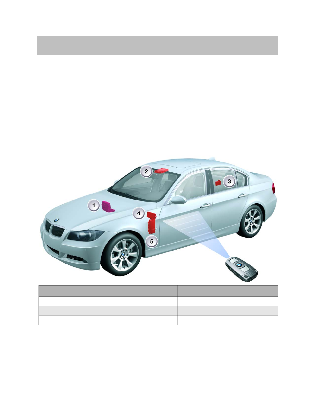
Control Modules for Sunroof Operation . . . . . . . . . . . . . . . . . . . . . . . . . .81
Car Access System 2 (CAS2) . . . . . . . . . . . . . . . . . . . . . . . . . . . . . . . .82
Footwell Module (FRM) . . . . . . . . . . . . . . . . . . . . . . . . . . . . . . . . . . . . . .82
Roof Function Center (FZD) . . . . . . . . . . . . . . . . . . . . . . . . . . . . . . . . . .82
Comfort Access (CA) . . . . . . . . . . . . . . . . . . . . . . . . . . . . . . . . . . . . . . . .82
Operation . . . . . . . . . . . . . . . . . . . . . . . . . . . . . . . . . . . . . . . . . . . . . . .82
Slide/Tilt Sunroof Button . . . . . . . . . . . . . . . . . . . . . . . . . . . . . . . . . .82
Remote Control/ID Transmitter . . . . . . . . . . . . . . . . . . . . . . . . . . . .82
Driver's Door Lock Barrel . . . . . . . . . . . . . . . . . . . . . . . . . . . . . . . . .82
Outer Door Handle . . . . . . . . . . . . . . . . . . . . . . . . . . . . . . . . . . . . . . .82
Slide/tilt Sunroof Motor . . . . . . . . . . . . . . . . . . . . . . . . . . . . . . . . . . . . . .83
Anti-trapping Protection . . . . . . . . . . . . . . . . . . . . . . . . . . . . . . . . . .83
Blocking Protection . . . . . . . . . . . . . . . . . . . . . . . . . . . . . . . . . . . . . .83
Thermal Protection . . . . . . . . . . . . . . . . . . . . . . . . . . . . . . . . . . . . . . .83
Panic Mode . . . . . . . . . . . . . . . . . . . . . . . . . . . . . . . . . . . . . . . . . . . . .83
Terminal 58g . . . . . . . . . . . . . . . . . . . . . . . . . . . . . . . . . . . . . . . . . . . .83
Control . . . . . . . . . . . . . . . . . . . . . . . . . . . . . . . . . . . . . . . . . . . . . . . . . . . . . . .84
Button for Slide/Tilt Sunroof . . . . . . . . . . . . . . . . . . . . . . . . . . . . . . . . . .84
Slide/Tilt Sunroof Motor . . . . . . . . . . . . . . . . . . . . . . . . . . . . . . . . . . . . . . . .84
Initialization . . . . . . . . . . . . . . . . . . . . . . . . . . . . . . . . . . . . . . . . . . . . . . . . . . .84
Procedure . . . . . . . . . . . . . . . . . . . . . . . . . . . . . . . . . . . . . . . . . . . . . . . . . .84
Interruption in Power Supply . . . . . . . . . . . . . . . . . . . . . . . . . . . . . .85
Deleting the Initialization . . . . . . . . . . . . . . . . . . . . . . . . . . . . . . . . . .85

Subject Page
Slide/Tilt Sunroof - Input/Output . . . . . . . . . . . . . . . . . . . . . . . . . . . . . . . .86
Slide/Tilt Sunroof - Circuit Diagram . . . . . . . . . . . . . . . . . . . . . . . . . . . . .88
Anti-Theft Alarm System (DWA) . . . . . . . . . . . . . . . . . . . . . . . . . . . . . . .91
Control Modules for System Operation . . . . . . . . . . . . . . . . . . . . . . . . . .91
Roof Functions Center (FZD) . . . . . . . . . . . . . . . . . . . . . . . . . . . . . . . . .91
Ultrasonic Passenger Compartment Sensor (USIS) . . . . . . . . . . . . .91
Footwell Module (FRM) . . . . . . . . . . . . . . . . . . . . . . . . . . . . . . . . . . . . . .92
Junction Box Electronics Control Module (JBE) . . . . . . . . . . . . . . . .92
Car Access System 2 (CAS2) . . . . . . . . . . . . . . . . . . . . . . . . . . . . . . . .92
Functions of the Anti-Theft Alarm System . . . . . . . . . . . . . . . . . . . . . . . .92
Arming the Anti-Theft Alarm System . . . . . . . . . . . . . . . . . . . . . . . . . .92
Deactivating Tilt Alarm & USIS . . . . . . . . . . . . . . . . . . . . . . . . . . . . . . .93
Disarming the Anti-Theft Alarm System . . . . . . . . . . . . . . . . . . . . . . .93
Unlocking the Luggage Compartment . . . . . . . . . . . . . . . . . . . . . . . . .94
Forced Disarming . . . . . . . . . . . . . . . . . . . . . . . . . . . . . . . . . . . . . . . . . . .94
No Crosswise Operation . . . . . . . . . . . . . . . . . . . . . . . . . . . . . . . . . . . . .94
Feedback from Anti-Theft Alarm System . . . . . . . . . . . . . . . . . . . . . . . . .94
Feedback via DWA LED . . . . . . . . . . . . . . . . . . . . . . . . . . . . . . . . . . . . .94
Feedback via Emergency Current Siren . . . . . . . . . . . . . . . . . . . . . . .95
Feedback via Blinking Lights . . . . . . . . . . . . . . . . . . . . . . . . . . . . . . . . .95
Comfort Access . . . . . . . . . . . . . . . . . . . . . . . . . . . . . . . . . . . . . . . . . . . .95
Alarm Trigger . . . . . . . . . . . . . . . . . . . . . . . . . . . . . . . . . . . . . . . . . . . . . . . . .96
Door Contact Signals . . . . . . . . . . . . . . . . . . . . . . . . . . . . . . . . . . . . . . . .96
Trunk Lid . . . . . . . . . . . . . . . . . . . . . . . . . . . . . . . . . . . . . . . . . . . . . . . . . .96
Hood . . . . . . . . . . . . . . . . . . . . . . . . . . . . . . . . . . . . . . . . . . . . . . . . . . . . . .96
Ultrasonic Passenger Compartment Sensor (USIS) . . . . . . . . . . . . .96
Tilt Alarm Sensor . . . . . . . . . . . . . . . . . . . . . . . . . . . . . . . . . . . . . . . . . . .97
Self-Monitoring of Emergency Current Siren . . . . . . . . . . . . . . . . . . .97
Line Monitoring - DWA Bus . . . . . . . . . . . . . . . . . . . . . . . . . . . . . . . . . .97
Alarm Output . . . . . . . . . . . . . . . . . . . . . . . . . . . . . . . . . . . . . . . . . . . . . . . . .98
Audible Alarm . . . . . . . . . . . . . . . . . . . . . . . . . . . . . . . . . . . . . . . . . . . . . .98
Visual Alarm . . . . . . . . . . . . . . . . . . . . . . . . . . . . . . . . . . . . . . . . . . . . . . . .98
Self- Contained/Integrated Alarm . . . . . . . . . . . . . . . . . . . . . . . . . . . . .98
Panic Mode . . . . . . . . . . . . . . . . . . . . . . . . . . . . . . . . . . . . . . . . . . . . . . . .99
Alarm Termination . . . . . . . . . . . . . . . . . . . . . . . . . . . . . . . . . . . . . . . . . . .99
Anti-Theft Alarm System - Input/Output . . . . . . . . . . . . . . . . . . . . . . . .100
Anti-Theft Alarm System - Circuit Diagram . . . . . . . . . . . . . . . . . . . . . .102
Electronic Steering Lock (ELV) . . . . . . . . . . . . . . . . . . . . . . . . . . . . . .104
Advantages of the ELV . . . . . . . . . . . . . . . . . . . . . . . . . . . . . . . . . . . . . . . .104
Control Modules for ELV . . . . . . . . . . . . . . . . . . . . . . . . . . . . . . . . . . . . . .104
Car Access System 2 (CAS2) . . . . . . . . . . . . . . . . . . . . . . . . . . . . . . .104

Subject Page
Dynamic Stability Control (DSC) . . . . . . . . . . . . . . . . . . . . . . . . . . . . .105
Junction Box Electronics Control Module (JBE) . . . . . . . . . . . . . . .105
Electric Steering Lock (ELV) . . . . . . . . . . . . . . . . . . . . . . . . . . . . . . . .105
Operation of ELV . . . . . . . . . . . . . . . . . . . . . . . . . . . . . . . . . . . . . . . . . . . . .105
Safety Concept . . . . . . . . . . . . . . . . . . . . . . . . . . . . . . . . . . . . . . . . . . . .105
Electronic Function . . . . . . . . . . . . . . . . . . . . . . . . . . . . . . . . . . . . . . . .105
Unlocking the Steering . . . . . . . . . . . . . . . . . . . . . . . . . . . . . . . . . . . . .106
Valid Remote Control . . . . . . . . . . . . . . . . . . . . . . . . . . . . . . . . . . . .106
Enable (release) of the Unlock Function . . . . . . . . . . . . . . . . . . .106
Unlocking the Steering . . . . . . . . . . . . . . . . . . . . . . . . . . . . . . . . . .106
Feedback . . . . . . . . . . . . . . . . . . . . . . . . . . . . . . . . . . . . . . . . . . . . . .107
Switching off the ELV control module . . . . . . . . . . . . . . . . . . . . .107
Locking the Steering . . . . . . . . . . . . . . . . . . . . . . . . . . . . . . . . . . . . . . .107
Lock Request . . . . . . . . . . . . . . . . . . . . . . . . . . . . . . . . . . . . . . . . . .107
ELV Control Module Switched on . . . . . . . . . . . . . . . . . . . . . . . . .107
Locking the Steering . . . . . . . . . . . . . . . . . . . . . . . . . . . . . . . . . . . .108
Feedback . . . . . . . . . . . . . . . . . . . . . . . . . . . . . . . . . . . . . . . . . . . . . .108
Switching off the ELV control module . . . . . . . . . . . . . . . . . . . . .108
Electric Steering Lock (ELV) - Circuit Diagram . . . . . . . . . . . . . . . . . . .109
ELV Mechanism . . . . . . . . . . . . . . . . . . . . . . . . . . . . . . . . . . . . . . . . . . .110
Locking Procedure . . . . . . . . . . . . . . . . . . . . . . . . . . . . . . . . . . . . . .111

7
E90 General Vehicle Electrical
General Vehicle Electrical
Model: E90
Production: From Start of Production
After completion of this module you will be able to:
• Explain distributed functions
• Diagnose the various electrical systems
• Discuss the operational signal paths of the various systems
• Identify the key control modules for each system

8
E90 General Vehicle Electrical
Introduction
With the new 3 Series multiple control modules will be involved in the operation of a sys-
tem, similar to the “distributed functions” approach which has been successfully imple-
mented on the E60, E63/64, E65 & E66. With the launch of the E90, the distributed
function concept will be continued and further developed.
The associated optimization of the wiring/cabling through fewer interfaces is also an
important aspect when evaluating cost reduction and assembly time.
For diagnosis, on the other hand, the concept of "distributed functions" signifies a new
challenge. In terms of the control module, it is no longer apparent what functions it initi-
ates.
In the E90 there are several systems (i.e. Central Locking, Power Windows and Interior
Lighting) whose functions are distributed over the following control modules:
Index Explanation Index Explanation
1Junction Box (JB) & Junction Box Elect (JBE) 4Car Access System 2 (CAS2)
2Roof Functions Center (FZD) 5Footwell Module (FRM)
3Comfort Access (CA)

9
E90 General Vehicle Electrical
To get a better understanding of the concept of “distributed functions” using the Central
Locking System as an example.
To date (E46), the "Central Locking" function was located primarily in the General Module
(GM) or, on the E60 in the Basic Body Module (KBM) and the door modules.
The "Central Locking" function in the E90 is distributed over several control modules
(Car Access System, Junction Box Electronics Control Module & Footwell Module).
Distributing functions over several control module offers the advantage that sensors and
actuators are connected directly to a control module in the vicinity of their installed loca-
tion, which result is shorter cable connections. By interlinking the control modules, it is
possible to exchange sensor data between them.
The primary control modules for the systems in the E90 are:
• Junction Box Electronics Control Module (JBE)
• Car Access 2 (CAS2)
• Footwell Module (FRM)
• Roof Function Center (FZD)
The distributed functions concept is used/identified in the
following General Vehicle Electrical Systems:
• Central Locking (ZV))
• Comfort Access (CA)
• Interior Lighting (IB)
• Power Windows (FH)
• Slide/tilt Sunroof (SHD)
• Anti-theft Alarm System (DWA)
• Electronic Steering Lock (ELV)
• Wiper Washer System
• Park Distance Control (PDC)
• Vehicle Exterior Lighting
• Adaptive Headlight Control
• Steering Column Switch Cluster (SZL)
• Outside Mirror
• Power Seats
• Rear Sun Shade

10
E90 General Vehicle Electrical
Primary Control Modules
Functions of Junction Box Electronics Control Module
The Junction Box Electronics Control Module (JBE) serves as:
• Gateway Module for vehicle Bus System (provides a pass-through function for
F-CAN)
• Evaluator & transmitter of sensor data for Kombi such as Engine Coolant Level,
Washer Fluid Level, Fuel Level, Hand Brake Contact (evaluated data is transmitted
on to the Instrument Cluster)
• Evaluator & transmitter of sensor data for IHKA such as Automatic Recirculation Air
Control, Coolant Pressure (evaluated data is transmitted on to the IHKA module)
• Activator of Compressor Valve and Rear Window Defogger (activation control data is
transmitted from IHKA module)
• Controller of Wipe/Wash functions, Heated Washer Jets, Seat Heating, Mirror
Heating, Water Valve, Relay 30g_f, Rear Power Windows, Rear Window Sun Shade
• Locking & Unlocking of complete vehicle
• Pass-through for Outside Temp Sensor
Park
Distance
Control
Roller
Sun Blind
Rear
Window
Defogger
Gateway
K-CAN
PT-CAN
D-Bus
JBE
Outside
Mirror
Wipe/wash
System
30g_f
Relay
Power
Windows
IHKA Seat
Heating
Rain and
Lights
Sensor
Anti-theft
Alarm
System
Instrument
Cluster
Central
Locking

11
E90 General Vehicle Electrical
Index Explanation Index Explanation
1Connection to Main Wiring Harness (54-pin) 3Direct contact to Power Distribution Box (23-pin)
2Connection to Instrument Cluster (54-pin) 4Connection to Main Wiring Harness (47-pin)

12
E90 General Vehicle Electrical
Functions of Footwell Module
The Footwell Module (FRM) serves as:
• Gateway Module for communication between devices connected to
the LIN Bus and K-CAN (Outside Mirror & Drivers Switch Cluster).
• Evaluator of data from Door Contacts and Door Lock Cylinders
• Activator/controller of all Exterior Lights, Adaptive Headlights,
• Controller of Front Power Windows, Electric Load Shut-down
• Activation of Power Window Anti-Trap
• Stores the Vehicle Order information
Adaptive
Headlight
Control
Outside
Mirror
Exterior
Lighting
FRM
Gateway
LIN-Bus
K-CAN
Interior
Lighting
Electric
Load
Shutdown
Central
Locking
System
Power
Windows
Door
Contact
Index Explanation Index Explanation
1Connection to Main Wiring Harness (51-pin) 3Connection to Instrument Cluster (46-pin)
2Connection to Main Wiring Harness (51-pin) 4

13
E90 General Vehicle Electrical
Functions of Roof Function Center
The Roof Function Center (FZD) serves as:
• Controller of Sunroof Functions
• Gateway for Rain Light Sensor (Data transmitted from RLS to FZD via LIN Bus
then transmitted via K-CAN from FZD to other modules)
• Evaluator of data from Condensation sensor and calculates relative humidity
(data is transmitted via K-CAN to IHKA)
• Evaluator of data from Interior Electrochromatic Rear View Mirror (data from mirror is
converted and transmitted to FRM via K-CAN, FRM dips the outside mirrors)
• Supplies power to Universal Garage Door opener
• Activation/Controller of Vanity Mirror lighting, Map/Reading and Interior Light
• Integration point for Passenger Airbag light, Microphone, and Emergency call button
Interior
Lighting
Electro-
chromatic
Interior Rear
View Mirror
Slide/tilt
Sunroof
Emergency
Call Button
Micro-
phone
Airbag
Indicator
Lamp
tion Sensor
LIN-Bus
K-CAN
FZD
Index Explanation Index Explanation
1Connection to Main Wiring Harness (20-pin) 3Connection to Main Wiring Harness (4-pin)
2Connection to Interior Rear View Mirror (20-pin) 4Connection to Rear Interior Lighting (20-pin)

14
E90 General Vehicle Electrical
Functions of Car Access System
The Car Access System 2 (CAS2) serves as:
• Ignition Switch/Terminal control
• Master controller for Central Locking, Comfort Access, Power Windows
and Sunroof (issues enable command)
• Actuator/Controller of Electronic Steering Lock
• “Key” validation device and Electronic Vehicle Immobilization
• Redundant data storage device for Vehicle Order
• Storage point for Condition Based Service (CBS) data
• Control of KL15 and KL 30g relays
Ignition
Switch
KL 30g
Relay
Central
Locking
CAS
Anti-theft
Alarm
(DWA)
Slide/tilt
Sunroof
KL 15
Relay
Power
Windows
Outside
Mirror
Interior
Lighting
Power
Seats
Electronic
Steering
Lock
Exterior
Lighting
Adaptive
Headlight
Control
Comfort
Access
Index Explanation Index Explanation
1Connection to Wiring Harness (42-pin) 2Ribbon Cable Connector (14-pin)

15
E90 General Vehicle Electrical
NOTES
PAGE

16
E90 General Vehicle Electrical
Car Access System 2 - Input/Output

17
E90 General Vehicle Electrical
Legend for Car Access System 2
Index Explanation Index Explanation
1Hood Contact Switch 22 Center-Lock Button
2Car Access System 2 CAS 2 23 Truck Lid Button, Interior
3Clutch Switch 24 Dynamic Stability Control (DSC)
4Brake Light Switch BLS Kl. R Terminal R
5Digital Motor Electronics DME/ECM Kl. 15 Terminal 15
6Intelligent Battery Sensor (IBS) Kl. 15 WUP Terminal 15, Wake-up
7Starter Kl. 15 ESV Terminal 15, Fuel Injectors
8Junction Box (JB) Kl. 30 Terminal 30
9Terminal 30g Relay Kl. 30g Terminal 30, Switched
10 Terminal 15, Load-Shedding Relay Kl. 30L Terminal 30, Load
11 Junction Box Electronics Control Module
(JBE) Kl. 50 Terminal 50
12 Identification Transmitter CAS-
Bus/K-Bus K-Bus Protocol
13 Comfort Access (CA) K-CAN Body CAN
14 Remote Control Receiver PT-CAN Powertrain CAN
15 Rear window antenna EWS Electronic Vehicle Immobilizer Signal
16 Electronic Outer Door Handle Module TAGE START-
DME Start, Digital Motor Electronics
17 Electric Steering Lock (ELV) 30 ELV Positive Supply ELV
18 Telematics Control Unit TCU FBD Remote Control Services
19 Relay, Fuel Injectors FBD ON Remote Control Services ON
20 Holder FBD OUT Remote Control Services OUT
21 START/STOP Button
22 Side airbag, front right

18
E90 General Vehicle Electrical
Car Access System 2 - Circuit Diagram

19
E90 General Vehicle Electrical
Legend for Car Access System 2
Index Explanation Index Explanation
1Hood Contact Switch 22 Center-Lock Button
2Car Access System 2 CAS 2 23 Truck Lid Button, Interior
3Clutch Switch 24 Dynamic Stability Control (DSC)
4Brake Light Switch BLS Kl. R Terminal R
5Digital Motor Electronics DME/ECM Kl. 15 Terminal 15
6Intelligent Battery Sensor (IBS) Kl. 15 WUP Terminal 15, Wake-up
7Starter Kl. 15 ESV Terminal 15, Fuel Injectors
8Junction Box (JB) Kl. 30 Terminal 30
9Terminal 30g Relay Kl. 30g Terminal 30, Switched
10 Terminal 15, Load-Shedding Relay Kl. 30L Terminal 30, Load
11 Junction Box Electronics Control Module
(JBE) Kl. 50 Terminal 50
12 Identification Transmitter CAS-
Bus/K-Bus K-Bus Protocol
13 Comfort Access (CA) K-CAN Body CAN
14 Remote Control Receiver PT-CAN Powertrain CAN
15 Rear window antenna EWS Electronic Vehicle Immobilizer Signal
16 Electronic Outer Door Handle Module TAGE START-
DME Start, Digital Motor Electronics
17 Electric Steering Lock (ELV) 30 ELV Positive Supply ELV
18 Telematics Control Unit TCU FBD Remote Control Services
19 Relay, Fuel Injectors FBD ON Remote Control Services ON
20 Holder FBD OUT Remote Control Services OUT
21 START/STOP Button
22 Side airbag, front right

20
E90 General Vehicle Electrical
On the E90, all doors as well as the trunk lid and fuel filler flap are integrated into the
Central Locking System.
The central locking can be operated via the following components:
• Remote control/identification transmitter
• Driver's door lock barrel (door lock)
• Center-lock button
• Electronic outer door handle module (TAGE) in connection with comfort access
Control Modules for Central Locking Function
Index Explanation Index Explanation
1Car Access System 2 (CAS2) 3Junction Box (JB)
2Footwell Module (FRM
Central Locking
Other manuals for E90
1
Table of contents
Other BMW Automobile manuals

BMW
BMW X6 - BROCHURE 2010 Instruction manual

BMW
BMW X5 - CATALOGUE User manual

BMW
BMW 2008 Z4 User manual

BMW
BMW X5 - CATALOGUE User manual

BMW
BMW SERIE 3 CONVERTIBLE 2003 User manual

BMW
BMW 4 series User manual

BMW
BMW 6 SERIES CONVERTIBLE User manual

BMW
BMW M4 User manual

BMW
BMW I01 User manual

BMW
BMW 01 41 0 155 307 User manual

BMW
BMW 3 SERIES CONVERTIBLE - CATALOGUE User manual

BMW
BMW SERIE 3 COUPE 2002 User manual

BMW
BMW M6 - User manual

BMW
BMW X5 2000 User manual

BMW
BMW AG User guide

BMW
BMW Z4 2005 User manual

BMW
BMW ACTIVE HYBRID 7 BROCHURE 2010 User manual

BMW
BMW 4 CONVERTIBLE 2022 Series User manual

BMW
BMW M5 Sedan 2013 User manual

BMW
BMW SERIE 3 SEDAN 2005 User manual