BMW Night Vision Operating and installation instructions

Initial Print Date: 03/06
Table of Contents
Subject Page
Introduction . . . . . . . . . . . . . . . . . . . . . . . . . . . . . . . . . . . . . . . . . . . . . . . . . .3
System Overview . . . . . . . . . . . . . . . . . . . . . . . . . . . . . . . . . . . . . . . . . . . . .4
Connection of Control Units . . . . . . . . . . . . . . . . . . . . . . . . . . . . . . . . . . . . .5
Control Unit and Camera . . . . . . . . . . . . . . . . . . . . . . . . . . . . . . . . . . . . . .5
K-CAN . . . . . . . . . . . . . . . . . . . . . . . . . . . . . . . . . . . . . . . . . . . . . . . . . . . . . .5
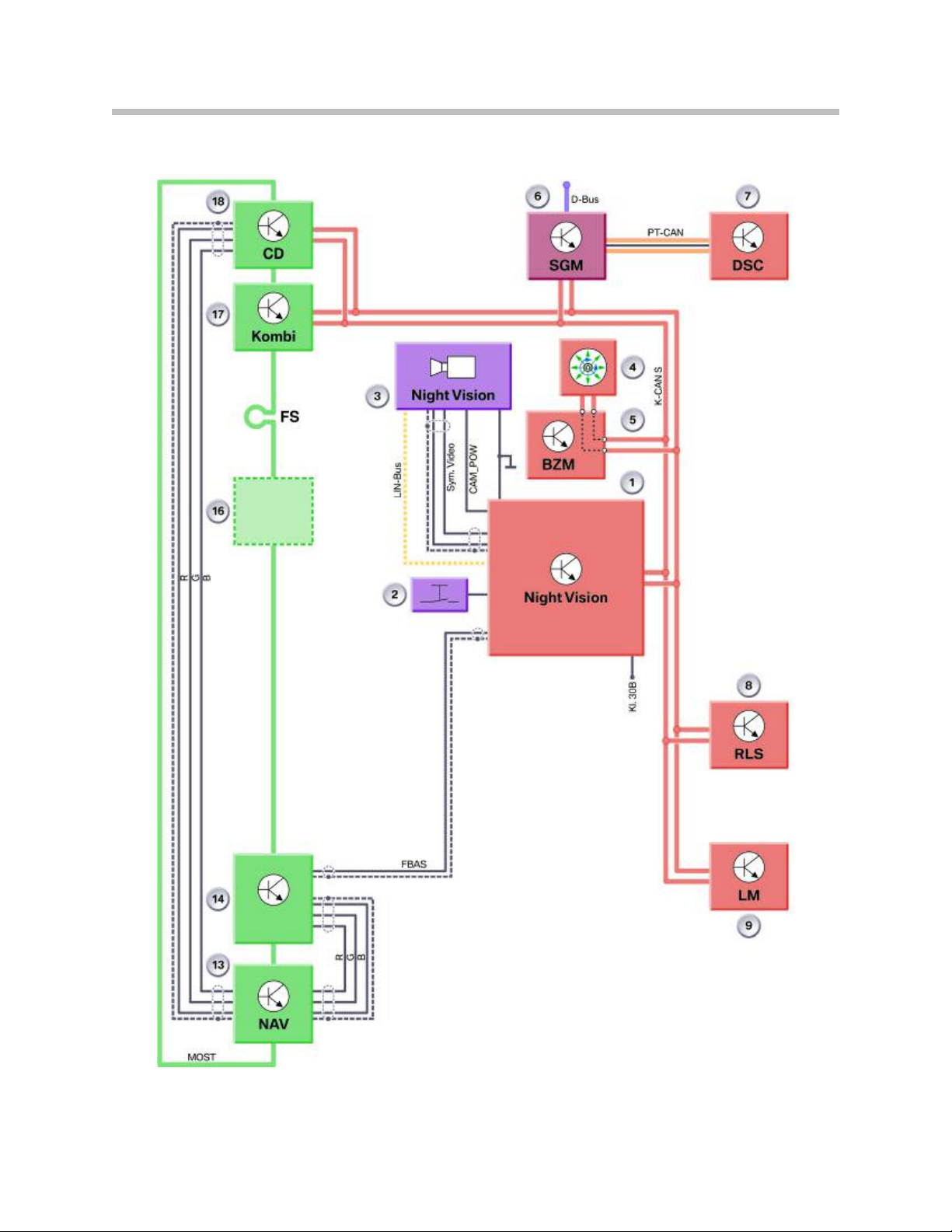
System Circuit Diagram (Front Equipment - E65/E66) . . . . . . . . . . . . . .6
Connection of Control Units . . . . . . . . . . . . . . . . . . . . . . . . . . . . . . . . . . . . .9
Control Unit and Camera . . . . . . . . . . . . . . . . . . . . . . . . . . . . . . . . . . . . . .9
K-CAN . . . . . . . . . . . . . . . . . . . . . . . . . . . . . . . . . . . . . . . . . . . . . . . . . . . . . .9
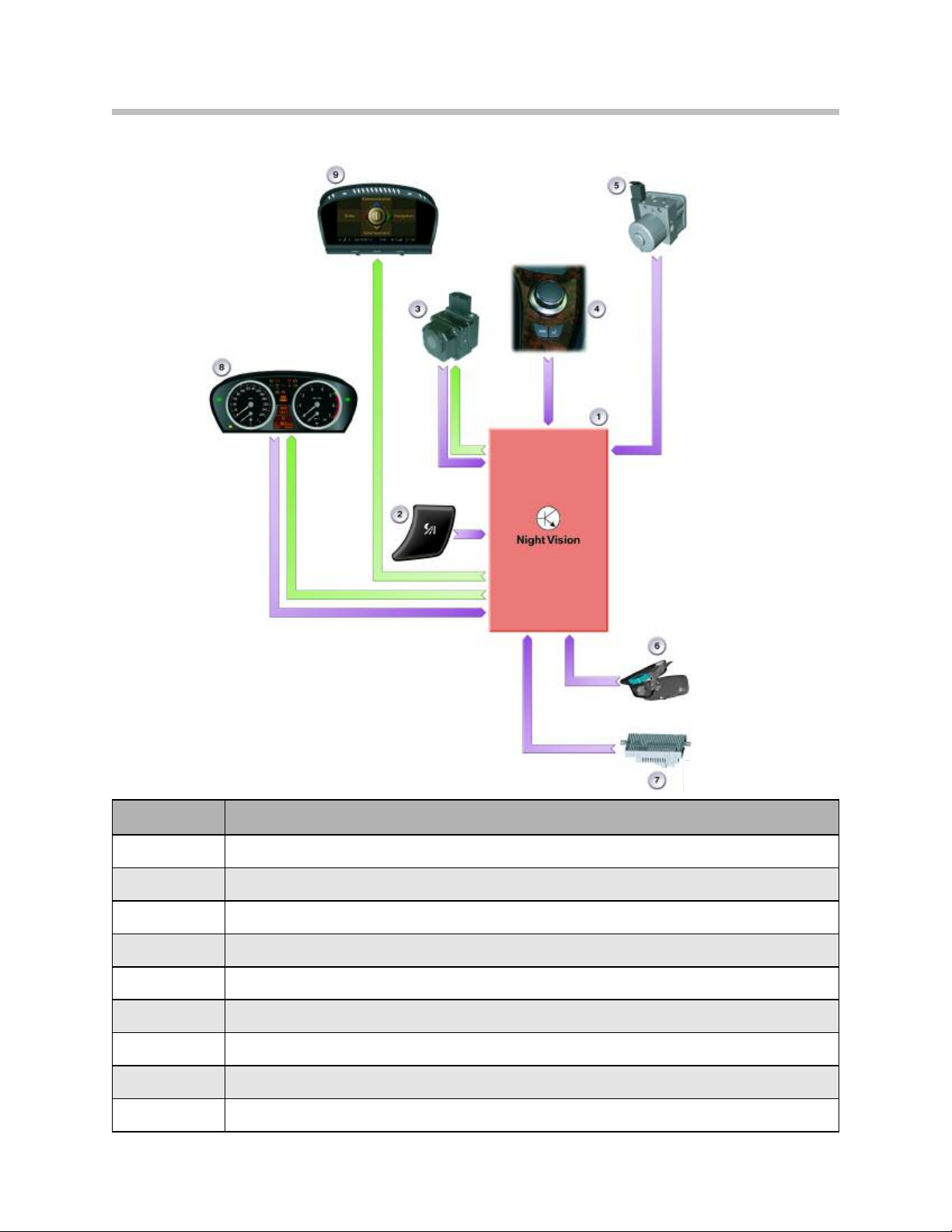
System Circuit Diagram (E60/E61/E63/E64) . . . . . . . . . . . . . . . . . . . . . .10
System Components . . . . . . . . . . . . . . . . . . . . . . . . . . . . . . . . . . . . . . . . .12
Components . . . . . . . . . . . . . . . . . . . . . . . . . . . . . . . . . . . . . . . . . . . . . . . . . .12
Night Vision Camera . . . . . . . . . . . . . . . . . . . . . . . . . . . . . . . . . . . . . . . .13
Night Vision Control Unit . . . . . . . . . . . . . . . . . . . . . . . . . . . . . . . . . . . . .14
Button in Light Switch Center . . . . . . . . . . . . . . . . . . . . . . . . . . . . . . . .14
Principles of Operation . . . . . . . . . . . . . . . . . . . . . . . . . . . . . . . . . . . . . . .15
Switch-On Conditions . . . . . . . . . . . . . . . . . . . . . . . . . . . . . . . . . . . . . . . . .16
Operation by iDrive . . . . . . . . . . . . . . . . . . . . . . . . . . . . . . . . . . . . . . . . . . . .17
Calling up Settings . . . . . . . . . . . . . . . . . . . . . . . . . . . . . . . . . . . . . . . . . .17
Calling Up Menu . . . . . . . . . . . . . . . . . . . . . . . . . . . . . . . . . . . . . . . . .17
Zoom - Angle of View of Camera . . . . . . . . . . . . . . . . . . . . . . . . . . . . .18
Bend/Curve Mode . . . . . . . . . . . . . . . . . . . . . . . . . . . . . . . . . . . . . . . . . .19
Full Screen . . . . . . . . . . . . . . . . . . . . . . . . . . . . . . . . . . . . . . . . . . . . . . . . .20
Contrast and Brightness . . . . . . . . . . . . . . . . . . . . . . . . . . . . . . . . . . . . .20
Visibility . . . . . . . . . . . . . . . . . . . . . . . . . . . . . . . . . . . . . . . . . . . . . . . . . . . .21
Service Information . . . . . . . . . . . . . . . . . . . . . . . . . . . . . . . . . . . . . . . . . .22
Axial Camera Adjustment . . . . . . . . . . . . . . . . . . . . . . . . . . . . . . . . . . . . . .22
Vertical Camera Adjustment . . . . . . . . . . . . . . . . . . . . . . . . . . . . . . . . . . . .22
Replacing Camera Washer Jet . . . . . . . . . . . . . . . . . . . . . . . . . . . . . . . . . .22
Displays in Event of a Fault . . . . . . . . . . . . . . . . . . . . . . . . . . . . . . . . . . . . .23
Component Location . . . . . . . . . . . . . . . . . . . . . . . . . . . . . . . . . . . . . . . . . .24
BMW Night Vision
Revision Date:

BMW Night Vision
Model: E60, E61, E63, E64, E65, E66
Production: March 2006
After completion of this module you will be able to:
• Familiarize yourself with the technology used in the BMW Night Vision system
• Know which components are responsible for the system’s operation
•Understand how to utilize the BMW Night Vision Feature
•Know the benefits to having this technology in the vehicle
2
BMW Night Vision

3
BMW Night Vision
The BMW Night Vision system provides the driver with a black-and-white image of the
driving environment ahead of the vehicle in the central information display (CID).
BMW Night Vision is a 100% passive system without active infrared illumination. Objects
situated ahead of the vehicle are shown in varying degrees of brightness depending on
the temperature of these objects. This enables the driver to detect in good time heat-
emitting objects such as people, animals, and other vehicles.
This thermal image is recorded with a Far Infrared camera (FIR) via a special imaging
sensor which detects the infrared radiation in a specific wavelength range.
The BMW system is distinguished from infrared systems with active illumination by its
resistance to dazzling, its long range, and its clearly structured image.
The system offers the following advantages:
•Improved vision in conditions of dusk and darkness
• No dazzling by the headlights of oncoming vehicles
• Highlighting of unilluminated, heat-emitting objects such as pedestrians, cyclists
vehicles and deer, etc.
• Better overview of the driving situation thanks to the depiction of the route of the
road beyond the headlight cone
• Enlarged depiction thanks to the zoom function of objects in the far distance at high
speeds
• Illumination of bends/curves thanks to the bend/curve mode (pivoting of image
detail)
•Illumination of dark courtyard and garage entrances
Note: The driving speed must be adapted to the relevant visibility conditions
in each case. BMW Night Vision is designed as a supporting system,
which, with a modified driving style, affords the driver an early, better
overview of the road conditions ahead of the vehicle.
Introduction
Image taken from CID

IPO Diagram (E65/E66)
4
BMW Night Vision
System Overview
Index Explanation
1Night Vision control unit
2Button in light switch center
3Night Vision camera
4Controller
5Dynamic Stability Control
6Rain/light sensor
7Light module
8Instrument cluster
9Control display

Connection of Control Units
Control Unit and Camera
The Night Vision control unit and the Night Vision camera are connected via the following
cables:
• LIN bus;
Diagnosis, programming and camera control
• Sym. Video;
Video signal from the camera
• CAN_POW;
Power supply from control unit to camera, heating of camera lens
• Ground;
Common earth/ground of camera and control unit for suppressing interference
The video signal between the camera and the control unit is transmitted via two cables as
a symmetrical, Analog video differential signal.
In the control unit the differential signal is converted into a CVBS signal and, depending
on the equipment specification, transmitted to the navigation system or the video module.
The camera is powered under the following conditions:
• Switching on of BMW Night Vision by the button in the light switch center
• Rain/light sensor detects dusk/half-light (driving lights are switched on)
The BMW Night Vision control unit is powered by the front distribution box via term. 30B.
K-CAN
The K-CAN connection of the Night Vision control unit serves to transmit the diagnosis
and programming data and to read out the information from the RLS (brightness), the LM
(driving lights on) and DSC (yaw rate, speed and steering angle). The signals from DSC
are placed on the K-CAN via the SGM. In addition, the control unit receives information
on the terminal status via the K-CAN.
5
BMW Night Vision

6
BMW Night Vision
System Circuit Diagram (Front Equipment - E65/E66)

Legend for System Circuit Diagram
7
BMW Night Vision
Index Explanation Index Explanation
1Night Vision ECU 18 Control Display
2Button in Light Switch Center D-Bus Diagnosis Bus
3Night Vision Camera PT-CAN Powertrain CAN
4Controller K-CAN Body CAN
5Center Console Switch Cluster MOST Media Oriented System Transport
6Safety Gateway Module LIN-Bus Local Interconnect Network Bus
7Dynamic Stability Control Kl. 30B Continuous Positive
8Rain/light Sensor Sym. Video Symmetrical, Analog Video
Differential Signal
9Light Module CAN_POW Power Supply, Night Vision Camera
13 Navigation System RGB Red-Green-Blue Video Signal Cable
14 Video Switch, Drive FBAS Composite Video Burst
Synchronization Signal
16 MOST Components (optional) FS MOST Direct Access
17 Instrument Cluster

8
BMW Night Vision
IPO Diagram (E60/E61/E63/E64)
Index Explanation
1Night Vision Control Unit
2Night Vision Button on Light Switch
3Night Vision Camera
4Controller
5Dynamic Stability Control
6Rain/Light Sensor
7Light Module
8Instrument Cluster
9Central Information Display

Connection of Control Units
Control Unit and Camera
The Night Vision control unit and the Night Vision camera are connected via the following
cables:
• LIN bus;
Diagnosis, programming and camera control
• Sym. Video;
Video signal from the camera
• CAN_POW;
Power supply from control unit to camera, heating of camera lens
• Ground;
Common ground of camera and control unit for suppressing interference
The video signal between the camera and the control unit is transmitted via two cables as
a symmetrical, Analog video differential signal.
In the control unit the differential signal is converted into a CVBS signal and, depending
on the equipment specification, transmitted to the navigation system or the video module.
The camera is powered under the following conditions:
• Switching on of BMW Night Vision by the button in the light switch center
• Rain/light sensor detects dusk/half-light (driving lights are switched on)
The BMW Night Vision control unit is powered by the front distribution box via term. 30B.
K-CAN
The K-CAN connection of the Night Vision control unit serves to transmit the diagnosis
and programming data and to read out the information from the RLS (brightness), the LM
(driving lights on) and DSC (yaw rate, speed and steering angle). The signals from DSC
are placed on the K-CAN via the KGM. In addition, the control unit receives information
on the terminal status via the K-CAN.
9
BMW Night Vision

10
BMW Night Vision
System Circuit Diagram (E60/E61/E63/E64)

11
BMW Night Vision
Legend for System Circuit Diagram (E60/E61/E63/E64)
Index Explanation Index Explanation
1Night Vision Camera 13 MOST Components (optional)
2Night Vision Control Unit D-Bus Diagnosis Bus
3Button in Light Switch Center PT-CAN Powertrain CAN
4Instrument Cluster K-CAN Body CAN
5Controller MOST Media Oriented System Transport
6Central Information Display LIN-Bus Local Interconnect Network Bus
7Car Communication Computer Sym. Video Symmetrical, Analog Video
Differential Signal
8Body Gateway Module (KGM) CAN_POW Power Supply, Night Vision Camera
9Dynamic Stability Control RGB Red-Green-Blue Video Signal Cable
10 Light Module FBAS Composite Video Burst
Synchronization Signal
11 Rain/light Sensor FS MOST Direct Access
12 Video Switch, Drive

Components
The BMW Night Vision system consists of the following components:
• Night Vision camera with camera bracket and camera washer jet
• Night Vision control unit
• Button in light switch center
• Sensor system
12
BMW Night Vision
Night Vision installation Locations
Index Explanation
1Night Vision Control Unit
2Control Display
3Controller
4Instrument Cluster
5Button in Light Switch Center
6Night Vision Camera
System Components

Night Vision Camera
The thermal imaging camera consists of a heated
optical element and a thermal imaging sensor. The
thermal imaging sensor is made up of a multitude
of sensor elements.
Each display pixel is assigned one such sensor ele-
ment. The sensor elements generate an electrical
signal as a function of the impinging intensity of
heat radiation.
The higher the temperature, the brighter the corre-
sponding pixel will be displayed. The heat radiation
is converted into electrical signals on the basis of
the principle of a change in resistance.
The image can be replaced up to 60 times per second. In order to ensure an image
of consistent quality, it is necessary for the camera to be calibrated roughly every 120
seconds. This calibration can take up to approx. 0.5 seconds. For this reason, the image
may be seen to freeze in the display.
The Night Vision camera is mounted with a bracket directly behind the left ventilation
grille on the bumper mounting bracket.
The camera is equipped with a sensor which detects heat-emitting objects in the Far
Infrared range (wavelengths from 8 µm to 15 µm).
The camera resolution is 320 x 240 pixels. The maximum angle of view is 36°. The
calculations for the "Bend/curve mode" functions are made in the camera. The camera
operates in an ambient-temperature range of - 104°F to 185°F (40°C to +85°C). The
camera and imaging sensor are thermally insulated to provide protection against heat
influences from the camera surroundings.
The washer jet is screwed to the camera bracket and is situated directly above the
camera's front lens. It is directly connected to the headlight washer system and therefore
operates in conjunction with the latter.
A heater element is incorporated on the inside of the camera-housing cover to prevent
the optical element from misting over or freezing up. The heater is activated when the
rain/light sensor detects precipitation or at temperatures below 32°F (0°C).
13
BMW Night Vision
Camera with Bracket (E65 shown)

Night Vision Control Unit
The control unit is accommodated in the front
device holder behind the glovebox.
The control unit increases the image data from
the camera from 320 x 240 pixels to 640 x 480
pixels. Only one detail is shown in the control
display. 640 x 240 pixels are displayed when the
"Full screen" function is activated while 400 x
240 pixels are displayed for the splitscreen function. The diagnosis, programming and
coding data are transmitted to the camera via the control unit.
The camera and the front-lens heater are powered via the control unit. In addition, the
control unit converts the symmetrical image data from the camera into a CVBS signal
and, depending on the equipment specification, makes this signal available to either the
navigation system or the video module.
The Night Vision control unit is accommodated in the front device holder behind the
glovebox.
The camera-housing cover features a 12-pin plug connection.
Button in Light Switch Center
The button for switching BMW Night Vision on and off is integrated in the light switch
center.
14
BMW Night Vision
12-pin Plug Connection
Switch/Button on E65/66 Switch/Button on E60/E61/E63/E64

Principles of Operation
The BMW Night Vision camera is a thermal imaging camera, which converts thermal
radiation into electronic signals and then into images visible to the human eye.
The thermal image is converted first by the sensor into electrical signals and then with
the aid of image-processing software into a visible image in the control display.
The sensor elements alter the resistance in proportion to the temperature. The higher
the temperature, the higher the electrical signal and the whiter the pixel will be shown.
Thanks to increased dynamic sensitivity, the sensor can generate a new image up to 60
times per second. This results in a softer and clearer image.
Heat radiation is absorbed and dissipated by virtually every solid or liquid body. Heat
radiation, however, is not visible to the human eye because it belongs in the long-wave
infrared range. From a physical standpoint, this represents electromagnetic waves with
a wavelength of 8 µm to 15 µm. This long-wave infrared radiation is known as Far
Infrared (FIR).
The advantage of utilizing radiation in the Far Infrared range is the greater range com-
pared with Near Infrared systems with a wavelength of 0.7 µm to 1.4 µm. These systems
require illumination with just this wavelength.
Essentially, FIR systems consist of an optical element, a thermal imaging camera, an
control unit and a display.
15
BMW Night Vision
Index Explanation Index Explanation
1Environment ahead of vehicle 4BMW Night Vision control unit
2Optical element 5Central Information Display
3Thermal Imaging Sensor
Diagram Representing Principle of Operation

Switch-On Conditions
BMW Night Vision is activated as soon as the button in the light switch center is pressed.
The following basic conditions can exist:
• The rain/light sensor detects sufficient
ambient light and the driving lights are
switched off; BMW Night Vision is ready for
operation approx. 2 seconds after the button
in the light switch center is pressed. A mes-
sage is shown in the control display during
this period of 2 seconds.
• The rain/light sensor detects insufficient
ambient light and the driving lights are
switched on; BMW Night Vision is ready for
operation immediately after the button is
pressed.
•In conditions of darkness (underground
car park), the driving lights are switched off
and the driving speed is less than 5 km/h;
BMW Night Vision is ready for operation
after the button in the light switch center is
pressed.
BMW Night Vision cannot be activated when:
• the driving lights are switched off,
• the rain/light sensor detects insufficient ambient light, and
• the driving speed is greater than 5 km/h
Once BMW Night Vision has been activated, a message appears in the control display to
the effect that the system cannot be used at night without driving lights.
16
BMW Night Vision
Switch/Button on E65/66
Switch/Button on E60/E61/E63/E64

Operation by iDrive
Calling up Settings
The individual functions and settings can be selected and activated via the iDrive.
The following settings can be called up:
• Night Vision off (not E65)
• Zoom
• Curve mode
• Full screen
• Contrast
• Brightness
Atick/check symbol indicates when zoom, bend/curve mode or full screen is activated.
Calling Up Menu
The BMW Night Vision menu can only be called up when the system is activated.
When the preconditions are in place, the menu can be called up for example from the
Start menu as follows:
• Briefly press the controller. The "BMW Night Vision" menu appears in the control
display
• Select the desired menu item, e.g. "Brightness", by turning the controller
• Press the controller to activate the function
• Set the desired value and confirm by pressing
• Select the menu item "Back" and quit the "BMW Night Vision" menu
17
BMW Night Vision
E65/E66 Settings Menu E60/E61/E63/E64 Settings Menu

Zoom - Angle of View of Camera
When the "Zoom" function is activated, BMW Night Vision automatically switches to a
1.5 times enlargement of the display at speeds in excess of 44 mph (70 km/h). The cam-
era's angle of view is reduced to 24° here. Zoom is deactivated automatically again when
the speed drops below 37 mph (60 km/h). The camera's angle of view reverts to 36°.
Zoom is calculated by the camera.
Note: The "Zoom" function can only be selected when the "Full screen" func-
tion is deactivated.
18
BMW Night Vision
Index Explanation
1Angle of view of 36° without zoom
2Angle of view of 24° with zoom
Angle of View of Camera

Bend/Curve Mode
Depending on the driving situation, the image detail follows the cornering path of the
vehicle along the same lines as the directional headlights.
The image detail is calculated in the camera.
Bend/curve mode is only available when the "Zoom" function is activated.
For better understanding, the following graphic shows a driving situation in which the
"Bend/curve mode" function is activated.
19
BMW Night Vision
Index Explanation
1Driving situation without zoom
2Driving situation with zoom, direction of travel
3Cornering to the left, enlarged 1.5 x
4Cornering tothe right, enlarged 1.5 x

Full Screen
In the case of the "Full screen" function, the Assist window is removed and the thermal
image is shown over the entire width of the control display. 640 x 240 pixels (for full
screen) and 400 x 240 pixels (for split screen) are used to display the BMW Night Vision
image.
Contrast and Brightness
Both values can be personalized and changed on a scale between -10 and 10.
20
BMW Night Vision
Full Screen in Control Display
Adjusting Brightness
Table of contents
Other BMW Car Video System manuals

BMW
BMW 82 82 0 304 134 User manual

BMW
BMW Advanced Car Eye 3.0 Pro User manual

BMW
BMW Head Unt High 3 Installation guide

BMW
BMW BMW-APIX-PAS-TDM User manual

BMW
BMW PIP Installation and operation manual

BMW
BMW G12 Installation guide

BMW
BMW iDrive 4+ User manual

BMW
BMW X5 DVD Video System II User manual

BMW
BMW E90 User manual

BMW
BMW iDrive 4+ User manual
Popular Car Video System manuals by other brands

Metra Electronics
Metra Electronics 95-7899 installation instructions

Boss Audio Systems
Boss Audio Systems BV12.1MC user manual

Clarion
Clarion MAX667VD Owner's manual & installation manual

Pyle view
Pyle view PLHR97W manual

ASA Electronics
ASA Electronics Voyager VOM-73SNWIN Operation manual

Sony
Sony DVX 11B Installation/connections