BMW E90 User manual

Initial Print Date: 03/05
Table of Contents
Subject Page
Introduction to Information & Communication Technology . . . . . . .4
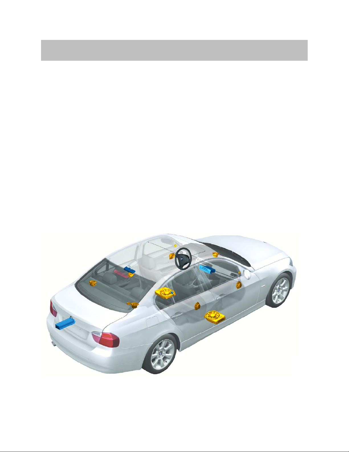
Audio Systems . . . . . . . . . . . . . . . . . . . . . . . . . . . . . . . . . . . . . . . . . . . . . . . .5
System Components and Features . . . . . . . . . . . . . . . . . . . . . . . . . . . . . . .6
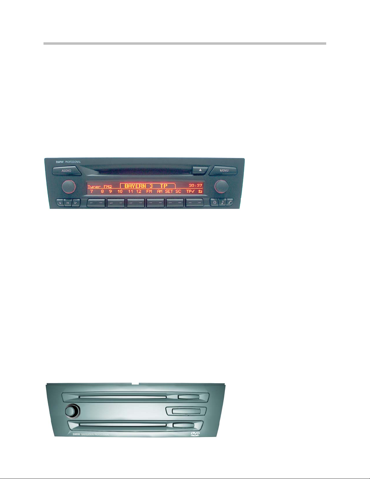
Radios Overview . . . . . . . . . . . . . . . . . . . . . . . . . . . . . . . . . . . . . . . . . . . . .6
‘Professional’ Radio (Rad2) . . . . . . . . . . . . . . . . . . . . . . . . . . . . . . . . . . . .7
Navigation System, Professional . . . . . . . . . . . . . . . . . . . . . . . . . . . . . . .7
Amplifiers and Speakers . . . . . . . . . . . . . . . . . . . . . . . . . . . . . . . . . . . . . .8
HiFi System . . . . . . . . . . . . . . . . . . . . . . . . . . . . . . . . . . . . . . . . . . . . . .9
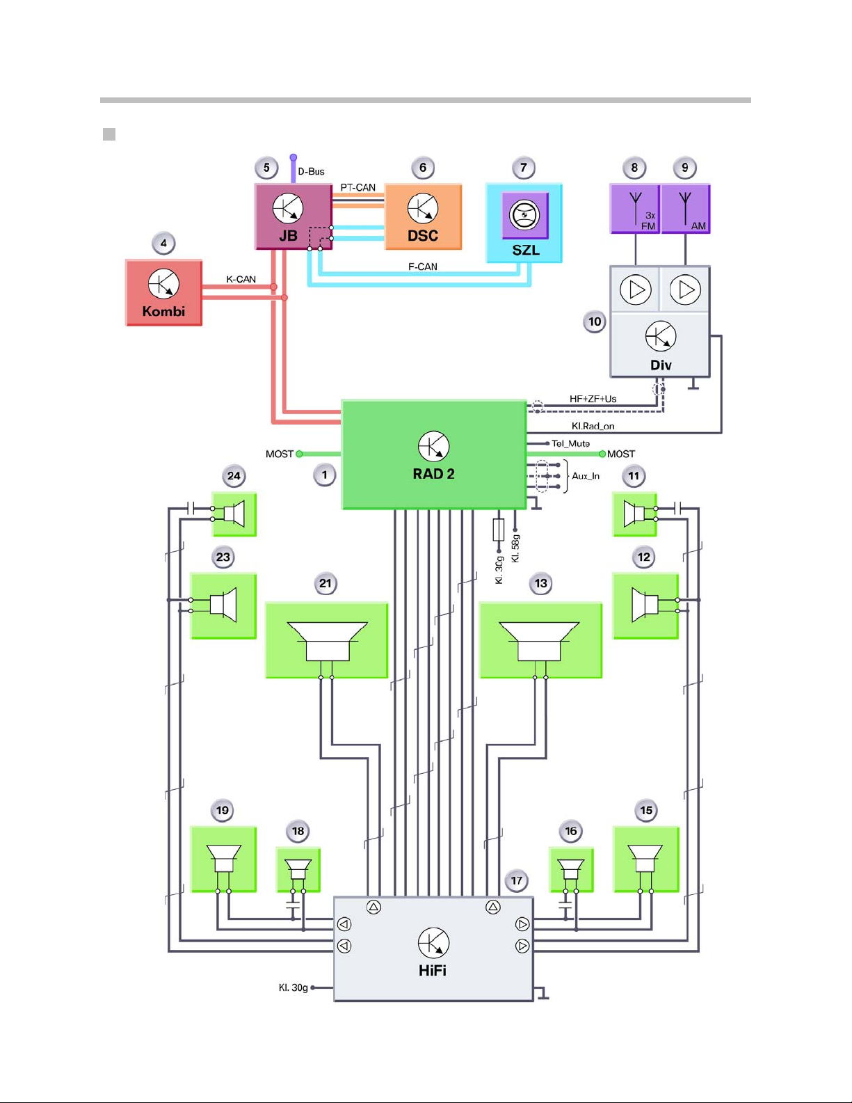
HiFi System Circuit Diagram . . . . . . . . . . . . . . . . . . . . . . . . . . . . . .10
Top-HiFi System . . . . . . . . . . . . . . . . . . . . . . . . . . . . . . . . . . . . . . . . .12
Top HiFi System Circuit Diagram . . . . . . . . . . . . . . . . . . . . . . . . . .14
Antennas . . . . . . . . . . . . . . . . . . . . . . . . . . . . . . . . . . . . . . . . . . . . . . . . . .16
Radio Antennas . . . . . . . . . . . . . . . . . . . . . . . . . . . . . . . . . . . . . . . . .17
FM Antenna Diversity . . . . . . . . . . . . . . . . . . . . . . . . . . . . . . . . . . . .18
Roof Aerial . . . . . . . . . . . . . . . . . . . . . . . . . . . . . . . . . . . . . . . . . . . . . .20
SDARS Satellite Tuner . . . . . . . . . . . . . . . . . . . . . . . . . . . . . . . . . . . . . . .21
CD Changer . . . . . . . . . . . . . . . . . . . . . . . . . . . . . . . . . . . . . . . . . . . . . . . .22
Audio Jack . . . . . . . . . . . . . . . . . . . . . . . . . . . . . . . . . . . . . . . . . . . . . . . . .23
Service Information . . . . . . . . . . . . . . . . . . . . . . . . . . . . . . . . . . . . . . . . . . . .24
Radio Service Mode . . . . . . . . . . . . . . . . . . . . . . . . . . . . . . . . . . . . . . . . .24
Accessing Service Mode - Rad2 . . . . . . . . . . . . . . . . . . . . . . . . . .24
Information Available . . . . . . . . . . . . . . . . . . . . . . . . . . . . . . . . . . . . .24
Accessing Service Mode - CCC . . . . . . . . . . . . . . . . . . . . . . . . . . .25
Reset . . . . . . . . . . . . . . . . . . . . . . . . . . . . . . . . . . . . . . . . . . . . . . . . . . . . . .25
Interference in Radio Reception . . . . . . . . . . . . . . . . . . . . . . . . . . . . . .25
MP3/WMA Playback . . . . . . . . . . . . . . . . . . . . . . . . . . . . . . . . . . . . . . . .26
Bit Rate . . . . . . . . . . . . . . . . . . . . . . . . . . . . . . . . . . . . . . . . . . . . . . . . .27
Navigation System . . . . . . . . . . . . . . . . . . . . . . . . . . . . . . . . . . . . . . . . . .28
System Circuit Diagram . . . . . . . . . . . . . . . . . . . . . . . . . . . . . . . . . . . . . . . .29
System Components and Features . . . . . . . . . . . . . . . . . . . . . . . . . . . . . .30
CCC . . . . . . . . . . . . . . . . . . . . . . . . . . . . . . . . . . . . . . . . . . . . . . . . . . . . . .30
DVD Drive . . . . . . . . . . . . . . . . . . . . . . . . . . . . . . . . . . . . . . . . . . . . . .30
Audio CD Drive . . . . . . . . . . . . . . . . . . . . . . . . . . . . . . . . . . . . . . . . . .30
Housing . . . . . . . . . . . . . . . . . . . . . . . . . . . . . . . . . . . . . . . . . . . . . . . .30
E90 Entertainment and Communication
Revision Date:

Subject Page
Audio Board (ASK) . . . . . . . . . . . . . . . . . . . . . . . . . . . . . . . . . . . . . . .31
Power Board . . . . . . . . . . . . . . . . . . . . . . . . . . . . . . . . . . . . . . . . . . . .31
Gyro Sensor . . . . . . . . . . . . . . . . . . . . . . . . . . . . . . . . . . . . . . . . . . . .31
HIP-Module (Host Independence Positioning Module) . . . . . . .31
Principles of Operation . . . . . . . . . . . . . . . . . . . . . . . . . . . . . . . . . . . . . . . . .33
Navigation Mode . . . . . . . . . . . . . . . . . . . . . . . . . . . . . . . . . . . . . . . . . . . .34
Service Information . . . . . . . . . . . . . . . . . . . . . . . . . . . . . . . . . . . . . . . . . . . .35
DVD . . . . . . . . . . . . . . . . . . . . . . . . . . . . . . . . . . . . . . . . . . . . . . . . . . . . . . .35
Media Ejection . . . . . . . . . . . . . . . . . . . . . . . . . . . . . . . . . . . . . . . . . . . . .35
Start-Up . . . . . . . . . . . . . . . . . . . . . . . . . . . . . . . . . . . . . . . . . . . . . . . . . . .35
Telephone . . . . . . . . . . . . . . . . . . . . . . . . . . . . . . . . . . . . . . . . . . . . . . . . . . .36
System Circuit Diagram . . . . . . . . . . . . . . . . . . . . . . . . . . . . . . . . . . . . . . . .38
Service Information . . . . . . . . . . . . . . . . . . . . . . . . . . . . . . . . . . . . . . . . . . . .40
Compatible Telephones . . . . . . . . . . . . . . . . . . . . . . . . . . . . . . . . . . . . .40
Pairing a Handset . . . . . . . . . . . . . . . . . . . . . . . . . . . . . . . . . . . . . . . . . . .40
v60i Phones . . . . . . . . . . . . . . . . . . . . . . . . . . . . . . . . . . . . . . . . . . . . . . . .40
Voice Recognition System . . . . . . . . . . . . . . . . . . . . . . . . . . . . . . . . . . .41
TCU . . . . . . . . . . . . . . . . . . . . . . . . . . . . . . . . . . . . . . . . . . . . . . . . . . . . . . . . .41
CCC . . . . . . . . . . . . . . . . . . . . . . . . . . . . . . . . . . . . . . . . . . . . . . . . . . . . . . . . .41

3
E90 Communication
Entertainment and Communication
Model: E90
Production: From Start of Production
After completion of this module you will be able to:
• Identify the different audio systems available
• Access service mode on the RAD2
• Know the TCU variant offered as optional equipment
• Understand what systems can play back MP3/MWA files

4
E90 Communication
Information and Communication Technology refers to various systems in the vehicle that
that inform or entertain the driver and passengers.
Depending on the equipment configuration (BMW Assist), the IKT also serves the
purpose of making available servicing-relevant data and sending messages in the
case of emergency.
For the first time in this vehicle class, a fibre optics-based bus is used for data transmis-
sion in information and communication applications (IKT). This bus is the so-called
MOST (Media Orientated Systems Transport) bus as already used on the E65, E60 and
E63/4.
In this section you will be informed about the information and communication technolo-
gy available in the new BMW3 Series (E90). It deals with the following topics:
• Audio systems
• Navigation systems
• Telephone systems
• Voice recognition systems
Introduction to Information & Communication Technology

5
E90 Communication
Audio Systems
Two audio sources are offered on the E90. Both are on the MOST bus and have CD
playing capabilities.
The base version utilizes a single cd drive and a dual LCD line readout and is referred to
as the RAD2 (‘Professional’ radio). This audio system can be ordered as a HiFi system
with 180 Watt capability or upgraded to Top-HiFi Logic7 with 420 Watts of power.
The second audio source is the familiar Car Communication Computer (CCC or
Navigation system, Professional). Because the CCC does not have an LCD readout,
it utilized the CID as a visual monitor. A vehicle equipped with CCC will always come
with the Top-HiFi Logic7 system with 420 Watts of power as standard.
The following new features have been introduced:
• New 'Professional' radio with MOST capabilities (RAD2 and CCC)
• Additional audio input for external devices
• Playback of MP3 files (RAD2 Directly / CCC with CD Changer)

System Components and Features
Radios Overview
The E90 is equipped with RAD2 (‘Professional’ Radio) as standard equipment.
6
E90 Communication
'Professional'
radio
'Professional'
navigation
system
SA663 SA609
Designation CD-73, MD-73 CCC
Display Two-line CID 8.8"
Manufacturer Alpine Siemens VDO
Bus connection K-CAN, MOST K-CAN, MOST
AM tuner
range
Single
LW,MW
Single
LW,MW,SW
FM tuner (RDS) Single Double
FM diversity
CD Yes
Yes
Yes
Yes Yes
Yes Yes
Yes Yes
Yes
Yes
Yes
Yes Planned
Yes
MD (instead of
CD)
--- ---
DVD ---
MP3 playback
Audio jack
AUX level
matching
---
Top-HiFi
operation
Telephone
operation
CD changer
operation

7
E90 Communication
‘Professional’ Radio (Rad2)
The 'Professional' radio is a new radio for the MOST system network.
The radio combines the following features:
• Player for CD/MP3/WMA files • Built in single radio tuner
• Most bus gateway to the K-CAN • Liquid crystal display
• Board computer readout • Personal profile management
The MP3 directory structure is the same as that of a PC. Up to 8 directory levels can be
represented. A maximum of 255 directories and a total of 999 music tracks per CD can
be managed.
T
E04-4453
Navigation System, Professional
The 'Professional' navigation system is based on the CCC (car communication comput-
er), the functions of which are already familiar from the E60 and E63/4.
The CCC combines the following control units in one housing:
• Navigation computer/GPS module; Map display and/or arrow view on CID (split
screen)
• RDS double tuner
• Audio system controller (ASK)
• MOST gateway
• Interface to control display (LVDS)
• DVD player
• CD player
When the navigation system is not in use, its DVD drive can be used to play audio CDs.
Together with the controller and CID, the CCC forms the iDrive system.

Amplifiers and Speakers
The audio systems in the E90 offers two choices:
• HiFi system -10 speakers w/separate amplifier
• Top-HiFi system (Logic7) - 13 speakers w/Logic7 amplifier
In addition to the higher achievable sound pressure, the audio systems are also distin-
guished by the improved system fidelity. For the customer, the additional features such as
the 7-band graphic equalizer and the spatial sound (Logic7) provide both visible as well
as audible added value.
The central basses are located under the front seats. They are coupled to the side sills,
thus enlarging the resonance volume necessary for bass reproduction.
The stereo, HiFi and Top-HiFi systems exhibit different performance features in terms of
symmetry of the sound field, sound pressure and fidelity of the frequency response.
Note: Even though the diameters of the speakers in the HiFi and Top-HiFi sys-
tems are the same, there are differences in the output of the speakers.
This is achieved by the use of different materials for the diaphragms,
coils, magnets etc.
To distinguish between them, the designations Medium and High are
used in the table above.
8
E90 Communication
HiFi Top-HiFi
Rad2 Standard audio system Optional
CCC ---- Standard audio system
Output
180 Watts total:
2 x 40W (2Ω) Bass
4 x 25W (2Ω)
420 Watts total:
2 x 70W (4Ω) Bass
7 x 40W (2Ω)
Max Sound Pressure 104 dB as from 50 Hz 110 dB as from 40 Hz
Bandwidth 40 Hz to 20 kHz 30 Hz to 20 kHz
Fidelity ± 3 dB ± 1.5 dB
Tweeter Manufacturer 26mm (medium)
Harman/Becker
26mm (high)
Harman/Becker
Mid-Rang Speaker
Manufacturer
100 mm (medium)
Harman/Becker
100 mm (high)
Harman/Becker
Central Base Speaker
Manufacturer
217 mm (medium)
Harman/Becker
217 mm (medium)
Harman/Becker

HiFi System
The analogue 6-channel 'HiFi' amplifier has the same technical specifications as the one
fitted in the E83. In the E90, however, it features settings specific to the E90 (diplexers,
equalizing).
The HiFi amplifier is located behind the rear left side panel trim in the luggage compart-
ment.
The audio signals are transmitted in analog form from the radios or navigation systems to
the HiFi amplifier. This amplifier amplifies the signals and transfers them to the speakers.
A total of 10 speakers are driven by 6 audio channels:
• A high-range and mid-range speaker in each front door
• A tweeter and a mid-range speaker on each side of the rear shelf
• A central bass speaker under each front seat
9
E90 Communication
TE04-5287
6
6
4
4
7
1
3 2
5
5
3 2
Index Explanation Index Explanation
1Rad2 5Tweeter, front
2Mid-range speakers, front 6Tweeter, rear
3Central woofers 7HiFi amplifier
4Mid-range speakers, rear
HiFi System Layout

HiFi System Circuit Diagram
10
E90 Communication

Legend for HiFi System Circuit Diagram
11
E90 Communication
Index Explanation Index Explanation
1'Professional' radio (RAD 2) 16 Tweeter, rear right
4Instrument cluster 17 HIFi Amplifier
5Junction box control unit 18 Tweeter, rear left
6Dynamic stability control 19 Mid-range speaker, rear left
7Steering column switch cluster 21 Central base speaker, left
8FM1, FM2 and FM3 aerials 23 Mid-range speaker, front left
9AM aerial 24 Tweeter, front left
10 Antenna amplifier with diversity module MOST Media Orientated System Transport
11 Tweeter, front right HF High frequency signal
12 Mid-range speaker, front right ZF Intermediate frequency signal
13 Central base speaker, right Us Changeover voltage, AM/FM
antenna diversity mode
15 Mid-range speaker, rear right Aux_In Audio input for additional
audio sources
KL
Rad_on Control signal or power supply Tel_
Mute Radio muting during telephone operation

Top-HiFi System
The digital 'Top-HiFi' amplifier with Logic7 (Surround Sound) is of identical design to that
used in the E60 and the E63/4. This amplifier is a MOST bus node and can be operated
only with radios or navigation systems with MOST capabilities.
The audio signals are sent in digital form via the fibre-optic cable (MOST bus) from the
radio or navigation systems to the 'Top-HiFi' amplifier. The amplifier converts the digital
signals to analogue signals, amplifies them and routes them to the speakers.
The sound adjustment (7-band equalizer, spatial sound, fader etc.) takes place prior to the
analogue conversion in the digital signal processor (DSP) of the amplifier. The Top-HiFi
amplifier is installed in the same location as the HiFi amplifier.
A total of 13 speakers are driven by 9 audio channels:
• A high-range and mid-range speaker in each front door
• A tweeter and a mid-range speaker on each side of the rear shelf
• A mid-range speaker in each rear door
• A mid-range speaker in the dashboard (Surround Sound)
• A central bass speaker under each front seat
12
E90 Communication
Top-HiFi Amplifier Mounting Location
Index Explanation
1Logic7 amplifier

13
E90 Communication
TE04-5288
6
6
4
4
7
1 9
8
3 2
5
5
3 2
10
10
Index Explanation Index Explanation
1CCC 6Tweeter, rear
2Mid-range speakers, front 7Top-HiFi amplifier
3Central Woofers 8CID
4Mid-range speakers, rear 9Mid-range speaker, front center
5Tweeter, front 10 Mid-range speakers, rear doors
Top-HiFi System Layout

Top-HiFi System Circuit Diagram
14
E90 Communication

Legend for Top-HiFi System Circuit Diagram
15
E90 Communication
Index Explanation Index Explanation
1Rad2 or CCC 16 Tweeter, rear right
2CID 17 Top HiFi (Logic7) Amplifier
3Controller 18 Tweeter, rear left
4Instrument cluster 19 Mid-range speaker, rear left
5Junction box control unit 20 Mid-range speaker, rear left (door)
6Dynamic stability control 21 Central base speaker, left
7Steering column switch cluster 22 Center speaker
8FM1, FM2 and FM3 aerials 23 Mid-range speaker, front left
9AM aerial 24 Tweeter, front left
10 Antenna amplifier with diversity module 25 Other MOST bus consumers
11 Tweeter, front right MOST Media Orientated System Transport
12 Mid-range speaker, front right HF High frequency signal
13 Central base speaker, right ZF Intermediate frequency signal
14 Mid-range speaker, rear right (door) Us Changeover voltage, AM/FM
antenna diversity mode
15 Mid-range speaker, rear right Aux_In Audio input for additional
audio sources
KL
Rad_on Control signal or power supply Tel_
Mute Radio muting during telephone operation
LVDS Low voltage differential signaling (digital) FS Most direct access (loop)

Antennas
The E90 can have up to 5 aerial systems depending on the optional equipment fitted:
• FM/AM radio (rear-window aerials)
• Digital radio (roof antenna)
• Navigation system (roof antenna)
• TV (rear-window aerials) - not for US
• Telephone (roof antenna) additionally:
- Bluetooth antenna in steering column trim panel for mobile telephone connection
- Emergency aerial in left rear wheel arch (only if premium package or option SA639)
In addition to those, there is also:
• Aerial for the remote control services (FBD)
• 6 aerials for the Comfort Access system (from 9/2005 option 322)
Note: An HBL filter is fitted suppresses interference from the third brake light.
16
E90 Communication
Index Explanation Index Explanation
1Antenna amplifier with diversity module 5FM2 and TV2 aerial
2FBD Aerial 6FM1 antenna
3Lockout circuit (filter) 7Third brake light (HBL) filter
4FM3 and TV1 aerial 8AM aerial
Antenna Locations

17
E90 Communication
Radio Antennas
The high-frequency signals from the radio transmitters are received via the rear-window
aerials (FM1, FM2, FM3 and AM).
The aerial amplifiers are in the Diversity module. There are separate ones for AM and FM.
The combined aerial amplifier and Diversity module is located on the headliner above the
rear window, concealed behind a cover.
Both aerial amplifiers are supplied with direct current when the radio is switched on (via
terminal Rad_On).
The high-frequency signals from the AM and FM aerials are passed via a ribbon cable
from the rear window to the combined aerial amplifier and Diversity module.
Aerial Amplifier and Diversity Module
Index Explanation Index Explanation
1AM/FM tuner signal connector (black) 4TV1 signal (green) not for US
2not for US 56-pin rear window aerial antenna
3TV2 signal (brown) not for US 66-pin power supply and FBD connector

FM Antenna Diversity
A quadruple FM aerial diversity system is fitted as standard on the E90.
FM antenna diversity comprises:
• FM1, FM2 and FM3 aerials
• FM4 aerial, formed by combining the signals from the FM1 and FM2 aerials
• FM antenna amplifier with antenna diversity module
For reasons of space, the rear window of the E90 can accommodate only three FM
aerials. The FM4 aerial is not a physical component. To improve FM reception, the FM4
aerial is created by overlaying the HF signals from the FM1 and FM2 aerials.
The signal quality of the currently selected FM antenna (FM1 to FM4) is evaluated and
assessed in the diversity module. The next FM antenna is selected if the signal quality of
the received radio station deteriorates in connection with the active antenna. The
changeover takes place such that no interruption can be heard.
The high-frequency signal from the active FM aerial at any particular time is fed by the
aerial amplifier and Diversity module via a co-axial cable to the tuner in the radio or navi-
gation system. The signal is demodulated in the tuner and output in the form of an audio
signal through the speakers.
The radio or navigation system detects that a diversity module is installed and generates
the changeover voltage Us and the intermediate frequency signal (ZF) necessary for
diversity operation. The ZF signal is analyzed by the electronic circuitry in the diversity
module and is a copy of the currently selected radio station transmission on a fixed fre-
quency of 10.7 MHz.
The changeover between AM reception, FM diversity mode and diagnosis mode is
effected by means of the DC voltage signal Us. This voltage is generated by the radio and
used in the diversity module for evaluation purposes.
Diversity mode is active at Us = 2.5 V. AM mode is active at Us = 0 V, i.e. the FM1 anten-
na is selected. Diagnosis mode is active at Us = 5 V.
In total, up to three signals are therefore applied on the coaxial cable simultaneously.
• HF signal (e.g. 87.5-108 MHz) from diversity module to radio
• Control DC voltage Us from the radio to the diversity module
• Intermediate frequency (fIF = 10.7 MHz) from the radio to the diversity module as
the basis for evaluating the quality of the RF signal.
18
E90 Communication

19
E90 Communication
Diversity Module Internal Schematic
Index Explanation Index Explanation
1Rear-window aerials FM1, FM2,
FM3 and AM 7Band-block filter for IF signal
2AM aerial amplifier 8Coaxial line to radio
3Band-pass filter for AM signal 9DC filter
4Aerial changeover switch for FM
aerials 10 Diversity electronics
5FM aerial amplifier 11 Band-pass filter for IF signal
6Band-pass filter for FM signal 12 Demodulator with signal evaluation
based on level and noise component
KL
Rad_on
Control signal or switched
voltage supply from radio HF RF signal to radio
Us Antenna diversity changeover
voltage from radio ZF IF signal from radio

Roof Aerial
There are two different variants of roof antenna for the E90:
• Vehicle equipped with TCU - GPS antenna needed for telematic feature
• Vehicle equipped with SDARS (Satellite Digital Radio Service - Sirius)
The roof aerial for SDARS reception has a larger housing compared with the version with-
out satellite radio capability.
Specifically, the roof aerial for all possible equipment options on the US version comprises:
• Mobile phone aerials
• Telematic Control Unit (TCU) telephone aerials
• GPS antenna
• SDARS aerial for satellite reception
• SDARS aerial for terrestrial reception
20
E90 Communication
SDARS Roof Aerial
Index Explanation
1Telephone aerials for mobile phone
and Telematic Control Unit (TCU)
2SDARS aerial for satellite reception
3GPS antenna
4SDARS aerial for terrestrial reception
5GPS signal connector
color code: blue
6SDARS signal, terrestrial
7Telephone signal: connector
color code: Bordeaux violet
8SDARS signal, satellite
9Telephone signal: connector
color code: Grey
Other manuals for E90
1
Table of contents
Other BMW Car Video System manuals

BMW
BMW G12 Installation guide

BMW
BMW Night Vision Operating and installation instructions

BMW
BMW Advanced Car Eye 3.0 Pro User manual

BMW
BMW Head Unt High 3 Installation guide

BMW
BMW PIP Installation and operation manual

BMW
BMW iDrive 4+ User manual

BMW
BMW BMW-APIX-PAS-TDM User manual

BMW
BMW X5 DVD Video System II User manual

BMW
BMW 82 82 0 304 134 User manual

BMW
BMW iDrive 4+ User manual