EN/2
Retrofit / Installation kit No. 65 12 0 137 910 (others see cover sheet)
Installation Instructions No. 01 29 0 137 927 Issue date: 06.2001
Contents
Section Page
1. Important information on installing the CD changer in the E38 . . . . . . . . . . . . . . . . 3
2. Preparations . . . . . . . . . . . . . . . . . . . . . . . . . . . . . . . . . . . . . . . . . . . . . . . . . . . . . . 4
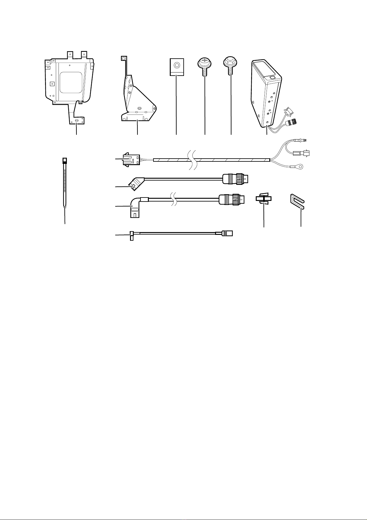
3. Parts list for cars with a production date prior to 09/98 . . . . . . . . . . . . . . . . . . . . . 5
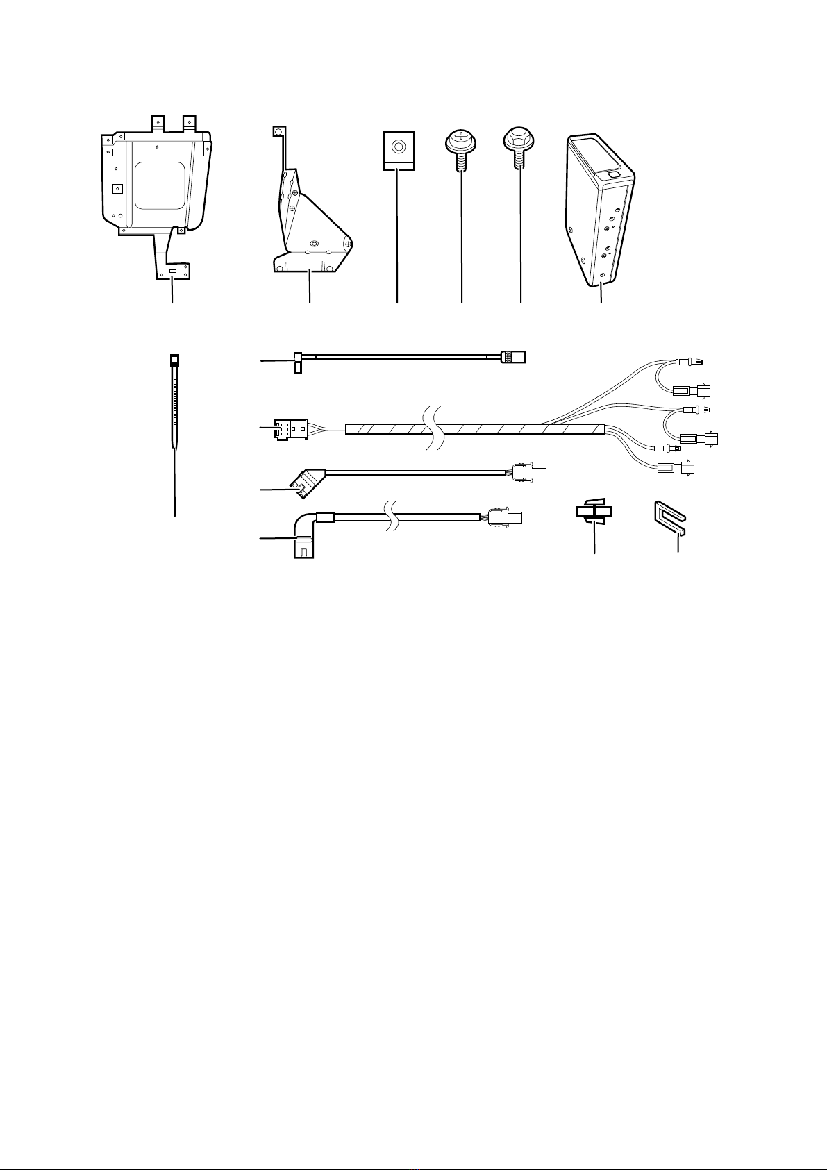
4. Parts list for cars with a production date after 09/98 . . . . . . . . . . . . . . . . . . . . . . . 6
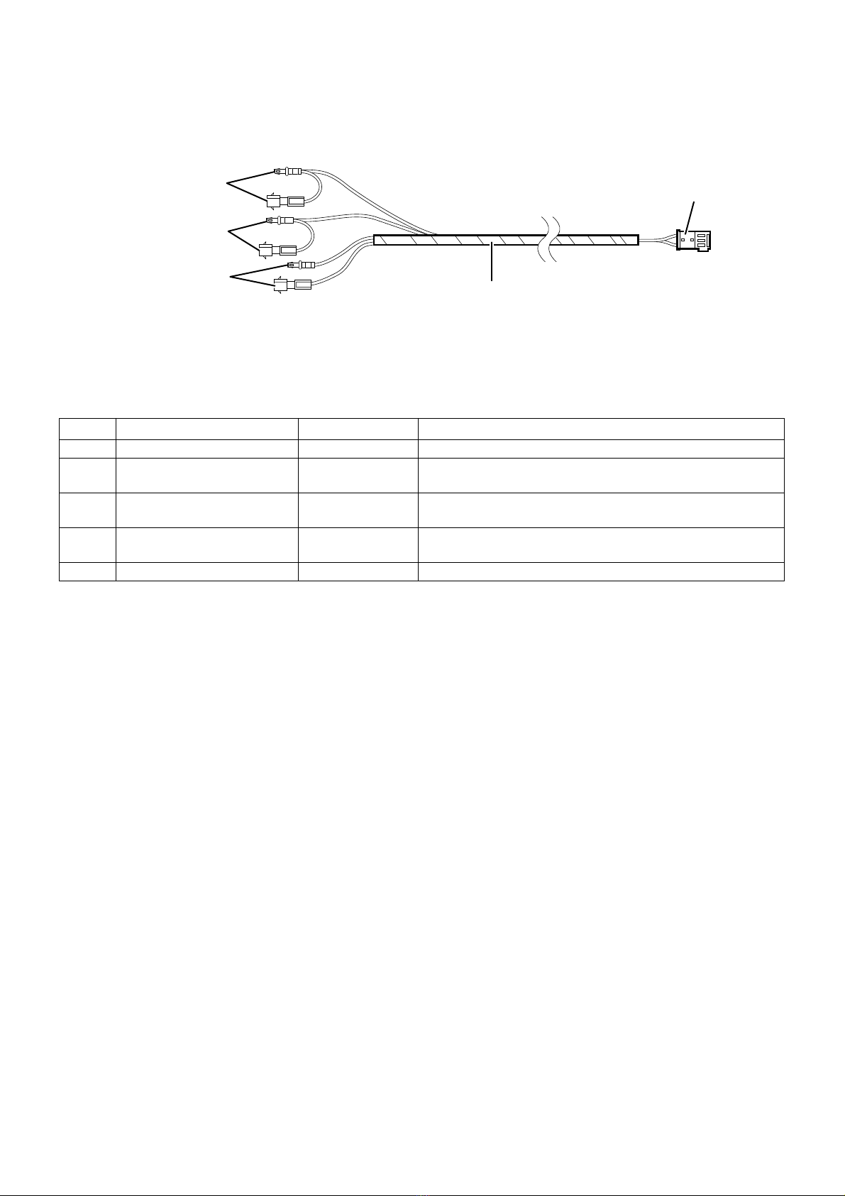
5. Power supply cable A connection diagram
for cars with a production date prior to 09/98 . . . . . . . . . . . . . . . . . . . . . . . . . . . . . 7
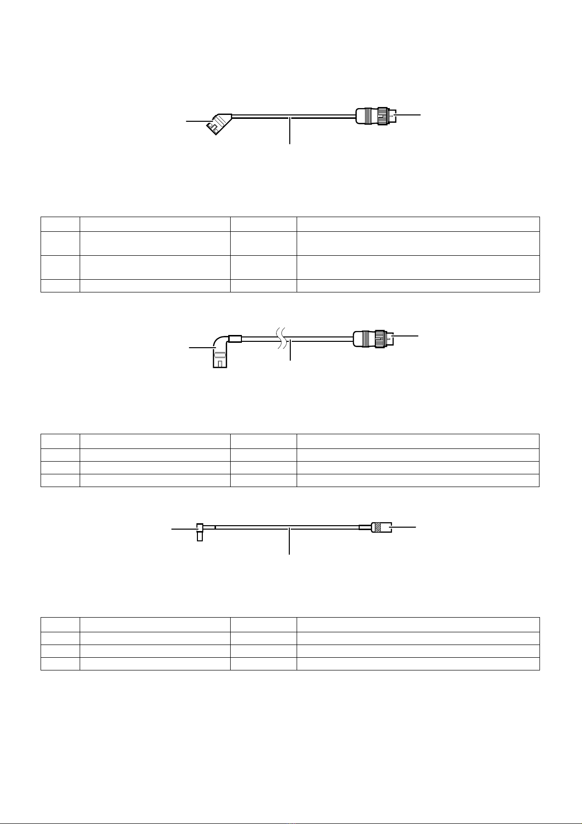
6. CD changer B, C and D connection cable connection diagram
for cars with a production date prior to 09/98 . . . . . . . . . . . . . . . . . . . . . . . . . . . . . 8
7. Power supply cable E connection diagram
for cars with a production date after 09/98 . . . . . . . . . . . . . . . . . . . . . . . . . . . . . . . 9
8. CD changer D, F and G connection cable connection diagram
for cars with a production date after 09/98 . . . . . . . . . . . . . . . . . . . . . . . . . . . . . . . 10
9. Installation and cabling diagram
(for cars with a production date prior to 09/98 with an on-board monitor radio only) 11
10. Installation and cabling diagram
(for cars with a production date prior to 09/98 without an on-board monitor radio only)
12
11. Installation and cabling diagram
(for cars with a production date after 09/98 with an on-board monitor radio only) . . 13
12. Installation and cabling diagram
(for cars with a production date after 09/98 without an on-board monitor radio only) 14
13. To install the CD changer
(cars with a production date prior to 09/98 and with an on-board monitor only) . . . 15
14. To install the CD changer
(cars with a production date prior to 09/98 and without an on-board monitor only) . 19
15. To install the CD changer (cars with a production date after 09/98
and with an on-board monitor without a DSP amplifier only) . . . . . . . . . . . . . . . . . . 23
16. To install the CD changer (cars with a production date after 09/98
and without an on-board monitor and without a DSP amplifier only) . . . . . . . . . . . . 26
17. To install the CD changer
(cars with a production date after 09/98 with a DSP amplifier only) . . . . . . . . . . . . . 30
18. Coding and concluding work and function . . . . . . . . . . . . . . . . . . . . . . . . . . . . . . . 33
19. Circuit diagram (cars with a production date prior to 09/98 only) . . . . . . . . . . . . . . 34
20. Circuit diagram (cars with a production date after 09/98 only) . . . . . . . . . . . . . . . . 35