BMW 65 12 0 151 239 User manual

Retrofit kit No. 65 12 0 151 239 and 65 12 0 301 482
Installation Instructions No. 01 29 0 151 240 Issue date: 01.2003
CD Changer Retrofit
BMW Z4 (E
85)
These installation instructions do not apply to cars with SA648 (BMW CD radio)
Important information
The retrofit kit is for use within the BMW dealership organisation only.
Subject to technical modifications.
Target group
The target group for these installation instructions is specialist personnel trained on BMW cars with the
appropriate specialist knowledge.
All work must be completed using the latest BMW repair manuals, circuit diagrams, servicing manuals and
work instructions in a rational order using the prescribed tools (special tools) and observing current health and
safety regulations.
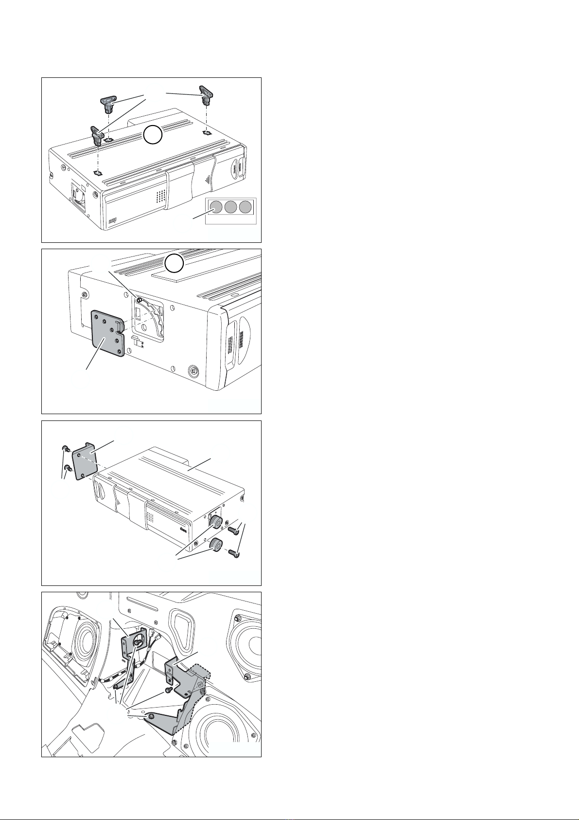
Installation information
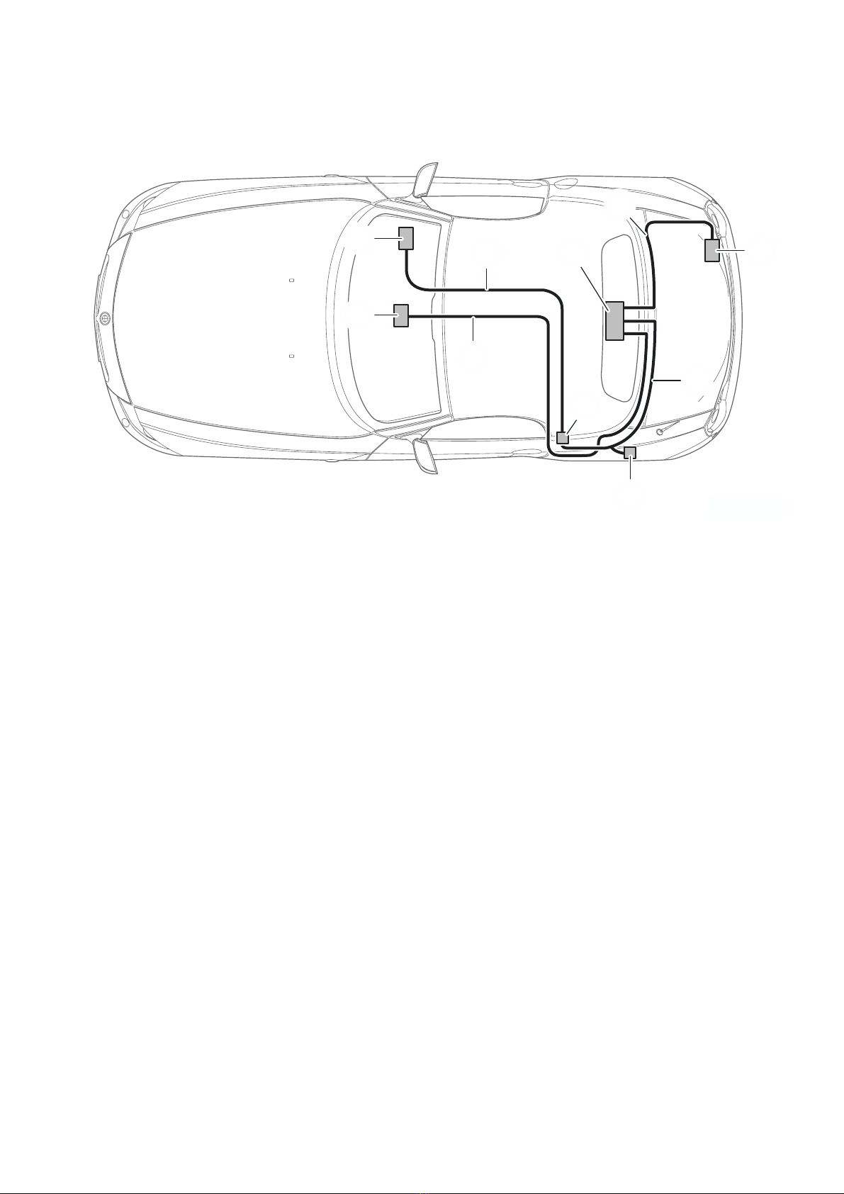
Ensure that the cables/lines are not kinked or damaged as you install them in the car.
The installed cables are to be secured with cable ties.
If the specified PIN chambers are occupied, bridges, double crimps or twin-lead terminals must be used.
After the installation work the retrofit must be coded using DISPlus, MoDiC III or GT-1 via the Retrofit path.
List of special equipment
The following special equipment must be taken into consideration when installing the retrofit kit.
The various sections contain corresponding information.
SA 609 Navigation system
SA677 Professional hi-fi system
Ordering instructions
Coax cable Dmust be ordered as well for cars with SA 677 (see EPC for part number and documentation).
Installation time
The installation time for cars without SA 609 is approx. 2.5 – 3 hours, for cars with SA 609 approx. 2 hours.
The installation times may vary depending on condition of the car and the equipment in it.
Pictograms
denotes instructions that draw your attention to special features.!
!denotes the end of the instruction or caution text.!
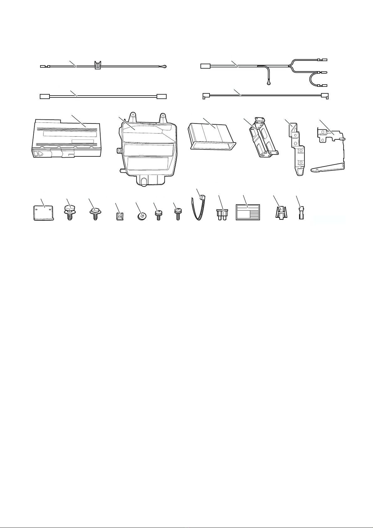
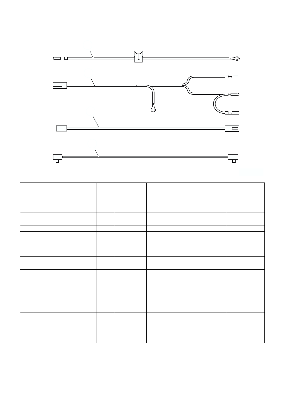
Parts and Accessories
Installation Instructions

EN/2
Retrofit kit No. 65 12 0 151 239 and 65 12 0 301 482
Installation Instructions No. 01 29 0 151 240 Issue date: 01.2003
Retrofit kit No.
65 12 0 151 239
65 12 0 301 482
See EPC for other retrofit kit part numbers.
Special tools required
Cleaning wedge 00 9 323
Removal tool 00 9 340

EN/3
Retrofit kit No. 65 12 0 151 239 and 65 12 0 301 482
Installation Instructions No. 01 29 0 151 240 Issue date: 01.2003
Contents
Section Page
1. Preparations. . . . . . . . . . . . . . . . . . . . . . . . . . . . . . . . . . . . . . . . . . . . . . . . . . . . . . . . . . . . . . . . . . . . . . . . . . 4
2. Parts list . . . . . . . . . . . . . . . . . . . . . . . . . . . . . . . . . . . . . . . . . . . . . . . . . . . . . . . . . . . . . . . . . . . . . . . . . . . . . 5
3. Connection diagram. . . . . . . . . . . . . . . . . . . . . . . . . . . . . . . . . . . . . . . . . . . . . . . . . . . . . . . . . . . . . . . . . . . 6
4. Installation and cabling diagram . . . . . . . . . . . . . . . . . . . . . . . . . . . . . . . . . . . . . . . . . . . . . . . . . . . . . . . . . 7
5. To install the CD changer . . . . . . . . . . . . . . . . . . . . . . . . . . . . . . . . . . . . . . . . . . . . . . . . . . . . . . . . . . . . . . 8
6. To route wiring harnesses (cars without SA 609 only) . . . . . . . . . . . . . . . . . . . . . . . . . . . . . . . . . . . . . 10
7. To route wiring harnesses (cars with SA 609 only) . . . . . . . . . . . . . . . . . . . . . . . . . . . . . . . . . . . . . . . . 12
8. Concluding work . . . . . . . . . . . . . . . . . . . . . . . . . . . . . . . . . . . . . . . . . . . . . . . . . . . . . . . . . . . . . . . . . . . . . 13
9. Circuit diagram . . . . . . . . . . . . . . . . . . . . . . . . . . . . . . . . . . . . . . . . . . . . . . . . . . . . . . . . . . . . . . . . . . . . . . . 14

EN/4
Retrofit kit No. 65 12 0 151 239 and 65 12 0 301 482
Installation Instructions No. 01 29 0 151 240 Issue date: 01.2003
1. Preparations
0
TIS instruction No.
Conduct a brief test ---
Disconnect the negative pole of the battery 12 00 ...
The following components must be removed first of all:
Cars without SA 609 only
Glove compartment 51 16 360
Unfasten the fuse box ---
Centre fresh air grille (cars without SA 677 only) 64 22 161
Radio receiver (cars without SA 677 only) 65 11 080
Switch unit on oddments box 61 31 057
Cover for selector lever (gear lever) 51 16 210
Cover for handbrake lever 51 16 ...
Trim for rear storage box 51 16 235
Cover for rear loudspeakers on both sides 65 12 020
Left side trim 51 43 010
Rear storage box 51 16 240
Boot floor trim 51 47 101
Undo the trim for the boot bulkhead at the bottom 51 47 140
Undo the left wheel arch trim in the boot 51 47 151
Cars with SA 609 only
Trim for rear storage box 51 16 235
Cover for rear loudspeakers on both sides 65 12 020
Rear storage box 51 16 240
Boot floor trim 51 47 101
Undo the trim for the boot bulkhead at the bottom 51 47 140

EN/5
Retrofit kit No. 65 12 0 151 239 and 65 12 0 301 482
Installation Instructions No. 01 29 0 151 240 Issue date: 01.2003
2. Parts list
0
Legend
APower supply wiring harness (cars without SA 609 only)
BCD changer wiring harness (cars without SA 609 only)
CLow-frequency cable (cars without SA 609 and cars without SA 677 only)
DCoax cable (cars with SA 677 only; not included in retrofit kit)
ECD changer
FOddments box (cars without SA 609 only)
GPush-in box (cars without SA 609 only)
HHolder (cars without SA 609 only)
IHolder (cars without SA 609 only)
JHolder (cars without SA 609 only)
KHolder
LHexagonal screw with washer M6 x 10 mm (4x; cars without SA 609 only)
MHexagonal screw with washer M5 x 14 mm (2x or 6x)
NSpeed nut M5 (2x or 6x)
OBush (2x)
PPhilips screw M4 x 6 mm (2x)
QPhilips screw M4 x 10 mm (2x)
RCable tie (10x or 20x)
SFusible link 7.5 A (cars without SA 609 only)
TInformation sticker (cars without SA 609 only)
USocket casing
VPlug casing
085 0003 Z
AB
D
C
EFGH
K L MOPQ
RST
N
IJ
V
U

EN/6
Retrofit kit No. 65 12 0 151 239 and 65 12 0 301 482
Installation Instructions No. 01 29 0 151 240 Issue date: 01.2003
3. Connection overview
0
0
Item Description Signal Cable colour /
Cross-section Connection location in the car Abbreviation / Slot
A Power supply wiring harness --- --- Cars without SA 609 only ---
A1 Plug contact Tl. 30 RT/BL
0.75 mm2
To plug casing under left side trim, natural
colour 12-pin plug
X322
PIN 4
A2 Cable lug M6 Tl. 30 RT/BL
0.75 mm2
To fuse box, post tl. 30 X1704
B CD changer wiring harness --- --- Cars without SA 609 only ---
B1 Black 3-pin socket casing --- --- To CD changer N22 X18180
B2 Socket contact Tl. 30 RT/BL
0.50 mm2
To socket casing under left side trim, natural
colour 12-pin plug
X322
PIN 4
B3 Plug contact I bus WS/RT/GE
0.35 mm2
To disconnected WS/RT/GE cable of the
standard wiring harness ---
B4 Socket contact I bus WS/RT/GE
0.35 mm2
To socket casing under left side trim, natural
colour 12-pin plug
X322
PIN 2
B5 Cable lug M6 Tl. 31 BR
0.5 mm2
To terminal 31 joint connector in boot on left X13016
C Low-frequency cable --- --- Cars without SA 609 and cars without SA 677
only ---
C1 Black 6-pin socket casing --- --- To CD changer N22 X18729
C2 Natural colour 12-pin socket casing --- --- To radio receiver N9 X13321
D Coax cable --- --- Cars with SA 677 only
Between CD changer N22 and amplifier A18 ---
085 0004 Z
A
B
C
D
A1
B1
C1
A2
B2
B3
B4
C2
B5

EN/7
Retrofit kit No. 65 12 0 151 239 and 65 12 0 301 482
Installation Instructions No. 01 29 0 151 240 Issue date: 01.2003
4. Installation and cabling diagram
0
Legend
1Fuse box
2Amplifier (cars with SA 677 only)
3Radio receiver
4Plug X322
5Terminal 31 joint connector X13016
APower supply wiring harness (cars without SA 609 only)
BCD changer wiring harness (cars without SA 609 only)
CLow-frequency cable (cars without SA 609 and cars without SA 677 only)
DCoax cable (cars with SA 677 only)
ECD changer
5
C
3
12
A
B
E
4
D
085 0005 Z

EN/8
Retrofit kit No. 65 12 0 151 239 and 65 12 0 301 482
Installation Instructions No. 01 29 0 151 240 Issue date: 01.2003
5. To install the CD changer
0
0
0
0
0Remove transport guards (1) of CD changer E.
Seal the openings with adhesive patches (2).
0Remove both covers (2) from CD changer Eand set
adjusting mechanism (1) to position “H”.
Fit covers (2).
0Use Philips screws Pto screw holder Konto CD changer
E.
Use Philips screws Qto screw bushes Oonto CD
changer E.
0Cars without SA 609 only
Use hexagonal screws Lto screw holders Iand Jonto
the rear panel.
BMW
CD CHANGER
COMPACT
E
1
2
085 0017 Z
M4x8mm MAX
H
V
E
1
2
085 0018 Z
H
V
BMW
CDCHANGER
COMPACT
O
P
Q
K
E
085 0020 Z
I
L
J
085 0019 Z

EN/9
Retrofit kit No. 65 12 0 151 239 and 65 12 0 301 482
Installation Instructions No. 01 29 0 151 240 Issue date: 01.2003
5. To install the CD changer
0
0
0
0
0All cars
Push speed nuts Nonto holders Iand J.
0Plug bushes Oon CD changer Einto holder Jand use
hexagonal screws Mto screw it onto holder I.
0Cars without SA 609 only
Use hexagonal screws Mto screw on holder H.
Insert push-in box Ginto holder Hwith the felt
downwards.
0Fit oddments box F.
I
J
N
085 0021 Z
COMPACT
BMW
CDCHANGER
M
O
E
J
I
085 0022 Z
COMPACT
BMW
CDCHANGER
H
G
M
085 0025 Z
COMPACT
BMW
CDCHANGER
F
085 0023 Z

EN/10
Retrofit kit No. 65 12 0 151 239 and 65 12 0 301 482
Installation Instructions No. 01 29 0 151 240 Issue date: 01.2003
6. To route wiring harnesses (cars without SA 609 only)
0
0 0013
0
0
0Screw branch A2 of power supply wiring harness Aonto
post tl. 30 (4) of fuse box (3).
Insert fuse holder (2) into relay holder (1) and plug in
fusible link 7.5 A S.
Route power supply wiring harness Ato the centre
console.
0
Low-frequency cable Cis not routed in cars with
SA 677.!
Route branch C2 of low-frequency cable Cfrom the
centre console to plug X18126 and insert it into free slot
(1).
0Route power supply wiring harness Aand low-frequency
cable Cunder the centre console to the left of the car.
0Connect branch A1 into PIN 4 of plug X322.
Connect branch B2 of CD changer wiring harness Binto
PIN 4 of plug X322.
3
A2
A
S
1
2
4
085 0010 Z
0
AUTO
1
8
2
0
2
2
2
4
2
6
X18126 1
C2 C
085 0011 Z
A
C
085 0012 Z
B2
A1
B
X322
085 0013 Z

EN/11
Retrofit kit No. 65 12 0 151 239 and 65 12 0 301 482
Installation Instructions No. 01 29 0 151 240 Issue date: 01.2003
6. To route wiring harnesses (cars without SA 609 only)
0
0
0
0
0Disconnect WS/RT/GE cable (1) from PIN 4 of plug X322
and fit socket casing Uonto it.
Fit plug casing Vonto branch B3 and connect it to socket
casing U.
Connect branch B4 into PIN 2 of plug X322.
Route CD changer wiring harness Band low-frequency
cable Calong the standard wiring harness into the boot.
0Screw branch B5 to joint connector terminal 31 X13016.
Connect branches B1 and C1 to CD changer E.
0Cars with SA 677 only
Connect coax cable Dto CD changer Eand route it to the
battery (1).
0Connect coax cable Dto amplifier (1).
B
B3
X322
C
1
U
V
B4
085 0014 Z
X13016
B5 C1
B1 E
085 0007 Z
D
E
1
085 0026 Z
1D
085 0024 Z

EN/12
Retrofit kit No. 65 12 0 151 239 and 65 12 0 301 482
Installation Instructions No. 01 29 0 151 240 Issue date: 01.2003
7. To route wiring harnesses (cars with SA 609 only)
0
0
0
0Cars without SA 677 only
Connect tied-back plugs X18180 and X18729 to CD
changer E.
0Cars with SA 677 only
Connect tied-back plug X18180 to CD changer E.
Connect coax cable Dto CD changer Eand route it to the
battery (1).
0Connect coax cable Dto amplifier (1).
X18180
X18729
E
085 0008 Z
D
E
1
X18180
085 0009 Z
1D
085 0024 Z

EN/13
Retrofit kit No. 65 12 0 151 239 and 65 12 0 301 482
Installation Instructions No. 01 29 0 151 240 Issue date: 01.2003
8. Concluding work
0
0
- Connect the battery
- Conduct a brief test
- Encode the CD changer using DISPlus, MoDiC III or GT-1 via path Retrofit.
- Conduct a function test
- Re-assemble the car
0Cars without SA 609 only
Install glove compartment (1) and stick on information
sticker Tas shown.
085 0015 Z
1
T

EN/14
Retrofit kit No. 65 12 0 151 239 and 65 12 0 301 482
Installation Instructions No. 01 29 0 151 240 Issue date: 01.2003
9. Circuit diagram
0
0
Legend
All the designations marked with an asterisk (*) apply only to these installation instructions or this circuit diagram
Legend
A* Fuse holder X322 Natural colour 12-pin plug
X1704 Post terminal 30
N9 Radio receiver X13016 Terminal 31 joint connector
N22 CD changer X13321 Natural colour 12-pin socket casing
X18180 Black 3-pin socket casing
X1* Plug contact X18729 Black 6-pin socket casing
BL blue RT red
BR brown SW black
GE yellow WS white
X18729
N22
CDW
NF L
CDW
NF -
CDW
NL R
0,5
WSRT
0,5
WSBR
0,5
WSBL
CDW
NF L
CDW
NF -
CDW
NF R
N9
X13321 829
124
X322 X1*
42
KL 30 I-BUS I-BUS
0,35
WSRTGE
0,5
RTBL
0,35
WSRTGE
23X18180
KL 30 I-BUS
N22
KL 31
1
0,5
BR
X13016
KL 31
A*
7,5 A
KL 30 KL 30
21
0,75
RTBL
0,75
RTBL
KL 30
KL 30
X1704
X18180
0,75
RTBL
085 0016 Z
This manual suits for next models
1
Table of contents
Other BMW CD Player manuals