BMZ Hyperion 15 User manual


Page 2of 28 Original installation instructions Hyperion Lithium Ion Energy Storage
Addresses, identification and notes
BMZ Batterien-Montage-Zentrum GmbH
Zeche Gustav 1
63791 Karlstein am Main
Germany
Tel.: +49 6188 9956-0
Fax: +49 6188 9956-900
Hyperion BMZ item no. 41871
Helios Battery Module item no. 37832-02
Model: Hyperion Lithium Ion Energy Storage
Country of Origin: Germany
Symbol: CE
+49 6188 9956-9830
Original installation instructions Hyperion Lithium Ion Energy Storage
Item number: #605990
Version: 1.2
As on: 06/08/2020
All rights reserved.
Imprint
Product
identification
Customer Service
Document
identification

Table of Contents
V1.2 | 06/08/2020 Page 3of 28
Table of Contents
1Safety 5
1.1 Important notes on this manual 5
1.1.1 Purpose 5
1.1.2 Target group 5
1.1.3 Storage 5
1.2 Symbol explanations 5
1.2.1 Explanations regarding safety instructions and warnings 5
1.2.2 Explanation of pictograms and symbols 6
1.3 Battery application area 7
1.3.1 Appropriate use 7
1.3.2 Perilous misuse 8
1.4 Main hazards 8
1.5 Qualification of the users 8
1.6 Personal protective equipment (PPE) 9
1.7 Emergency instructions 9
1.7.1 Measures in case of fire 9
1.7.2 Measures after gases or liquids have escaped 9
1.7.3 Measures after electric shock 9
2Product description 10
2.1 Important information about the product 10
2.1.1 Overall view 10
2.1.2 Conformity 10
2.2 Scope of delivery 11
2.3 Technical data 11
2.3.1 Performance features 11
2.3.2 Dimensions and weight of individual module 11
2.3.3 Compatible inverters 12
2.3.4 Supply, interfaces, connections 12
2.3.5 Ambient conditions 12
2.4 Status and SOC display 13
3Commissioning 13
3.1 Safety Instructions 13
3.2 Installation 13
3.2.1 Transport 13
3.2.2 Choice of installation site 14
3.2.3 Mounting 14
3.3 Assembly 15

Page 4of 28 Original installation instructions Hyperion Lithium Ion Energy Storage
3.3.1 Installing Helios modular batteries 15
3.3.2 Connect Helios modular batteries next to each other in
series 17
3.3.3 Closing the housing of the battery system 18
3.3.4 Adding battery modules 19
3.3.5 Disposal 19
3.4 Connecting the inverter 19
3.4.1 SMA Sunny Boy Storage 3.7 / 5.0 / 6.0 19
3.4.2 Kostal PLENTICORE plus 20
3.5 Putting the Hyperion storage system into operation 22
4Repair 22
5Decommissioning, storage 22
5.1 Safety regulations 22
5.2 Storage conditions 22
5.2.1 Storage period 22
5.2.2 Physical conditions 22
5.2.3 Cleaning 23
6Packing and transport 23
7Disposal 23
8Appendix 24
8.1 BMS master, DC-DC converter and relay in the Hyperion 24
8.2 Assignment BMS master inverter interface (X2) 24
8.3 Adjusting system voltage with SMA SB Storage 25
9Further directories 26
9.1 Glossary 26
9.2 List of tables 26
9.3 List of figures 26

1 Safety
V1.2 | 06/08/2020 Page 5of 28
1Safety
Before installing the battery system, read these instructions carefully.
Please follow the safety and warning instructions carefully to avoid damage to
persons, objects and the environment.
CAUTION
Risk of burns if you fail to adhere to the safety instructions.
During operation, heat can be generated by live parts, overload,
arc or short circuit. Touching hot surfaces can cause minor burns.
Read the operating instructions carefully before
using the modular battery.
1.1 Important notes on this manual
1.1.1 Purpose
This document describes the installation of a BMZ Hyperion battery system in
combination with SMA Sunny Boy Storage 3.7/5.0/6.0 or Kostal PLENTICORE plus.
1.1.2 Target group
The installation instructions are intended exclusively for qualified electricians.
1.1.3 Storage
This manual is part of the battery. For a safe installation, the manual must be
accessible to the installers.
Keep this manual near the battery.
Pass this manual on to the next owner of the battery.
1.2 Symbol explanations
1.2.1 Explanations regarding safety instructions and warnings
Safety instructions are universally valid and can be found in a safety chapter or at the
beginning of a chapter.
Safety Instructions

1 Safety
Page 6of 28 Original installation instructions Hyperion Lithium Ion Energy Storage
Warnings are placed directly before the instructions of the respective action. They
help you to avoid dangers during the upcoming action. They consist of the following
elements:
Warning
triangle
indicates all hazards with regard to death or injury along with a signal word.
Signal word
DANGER
denotes a hazard with a high degree of risk. Failure to avoid exposure to it will
result in death or serious injury.
WARNING
denotes a hazard with a medium degree of risk. Failure to avoid exposure to it
can result in death or serious injury.
CAUTION
denotes a hazard with a low degree of risk. Failure to avoid exposure to it can
result in a minor injury.
ATTENTION
indicates hazard concerning objects. Failure to avoid exposure to it can result in
damage to property.
Type and
source of the
danger
states the nature of the danger and what causes it
Consequence
indicates what can happen if you do not follow the warning
Call for action
describes what you must do to protect yourself
from the danger
Additional
symbols,
pictograms
can be used in addition to the warning triangle. Warning signs (yellow) indicate
the danger. Prohibition signs (red) and mandatory signs (blue) represent
remedial measures.
1.2.2 Explanation of pictograms and symbols
Symbols
Declaration
General warning sign.
Note additional information.
Warning of dangerous voltage
Warning of dangers from batteries that are being charged
Warning of flammable substances
Hot surface warning
Warnings
Table 1: Warnings
Table 2: Explanation of
the symbols used

1 Safety
V1.2 | 06/08/2020 Page 7of 28
Warning of hand injuries
No access for persons who have pacemakers or implanted defibrillators
Manual lifting prohibited.
General commandment sign
Note additional information.
Adhere to instructions.
Use foot protection.
Use hand protection.
Do not dispose of batteries with household garbage.
1.3 Battery application area
1.3.1 Appropriate use
The Hyperion Lithium Ion Energy Storage is a battery system. It serves as an energy
storage device within an electricity storage system for private households and small
businesses. It enables you to temporarily store self-produced electricity, e. g. from
photovoltaic - or CHP (cogeneration of heat and power) plants. The electricity can
later be used when needed.
In a battery system, 3 to 6 Helios modular batteries can be connected to one another
in series.
BMZ GmbH is not liable for personal injury and/or material damage due to improper
use of the energy storage system.
The battery system is a self-contained unit which is only functional after proper
installation with an approved inverter.
A maximum of 6 modular batteries can be connected serially in the Hyperion battery
system.
Battery system
Limits

1 Safety
Page 8of 28 Original installation instructions Hyperion Lithium Ion Energy Storage
In order to avoid dangers such as water pipe bursting, the modular batteries must be
stored at least 15 cm above the floor. Proper installation of the Hyperion fire pump
ensures that the active electrical components are at least 15 cm above the floor.
The Hyperion battery system may:
only be used with Helios modular batteries.
only be used with compatible inverters.
only be used in closed rooms.
only be used in an undamaged condition and in accordance with the
operating instructions.
Any other usage is not intended.
1.3.2 Perilous misuse
Do not use the battery system with other modular batteries.
Do not use the battery system outside its performance limits.
Do not install the battery system in rooms at risk of flooding.
Do not connect the battery system to devices not approved for this
purpose.
Do not open modular batteries. The modular battery may only be
opened by trained service personnel of BMZ GmbH.
1.4 Main hazards
You can expect zero danger from the battery under normal conditions. The battery
corresponds to the state of the art in science and technology. However, it is
impossible to completely exclude risks if the battery is misused or in the event of
technical failure. In case of lithium-ion batteries, these generally include fire,
explosion, chemical burns, and electric shock.
The product-specific risk of hazards is elevated by
water (e. g. flooding),
heat exposure (> 70 °C), and
failure or malfunction of the control system due to electromagnetic
radiation.
Touching live components may cause an electric shock when modular batteries are
connected in series. The electric shock can have thermal or muscle paralysing effects.
The latter can lead to ventricular fibrillation, cardiac arrest or respiratory paralysis, or
death.
Overload, short circuit or arcing can cause a lithium-ion fire with thermal runaway.
People can be hit by electrolyte or molten material. In the event of fire, there is a risk
of suffocation due to lack of oxygen and a risk of poisoning due to toxic fumes.
1.5 Qualification of the users
Only the electricians qualified by BMZ GmbH or BMZ GmbH itself may install the
battery system.
Electric shock
Fire

1 Safety
V1.2 | 06/08/2020 Page 9of 28
Do not leave the children unattended or allow them to be near the battery system.
High currents have effects on medical implants.
People with implants must be careful not to be in the direct vicinity of
the battery during operation.
1.6 Personal protective equipment (PPE)
Use foot protection and hand protection during assembly.
1.7 Emergency instructions
1.7.1 Measures in case of fire
Do not inhale smoke and vapours.
Report a lithium-ion fire to the fire department.
If possible: close the doors.
If possible: cool the modular battery with water. Avoid contact with the
extinguishing water!
1.7.2 Measures after gases or liquids have escaped
Escaping gases can cause respiratory problems.
Ventilate immediately or go out into the fresh air, in more extreme
cases, call a doctor immediately.
Skin contact may cause skin irritation.
Wash skin thoroughly with soap and water.
Eye contact may cause irritation to the eyes.
Immediately rinse eyes thoroughly with water for 15 minutes, then
consult a doctor.
1.7.3 Measures after electric shock
Ensure that the system is at zero voltage.
For unconscious patients: Ensure respiration and cardiovascular
function. If necessary, initiate cardiopulmonary resuscitation
immediately.
For responsive patients: Cool burn injuries and cover them by dressing
the wound.
Children
People with
implants
Inhalation
Skin contact
Eye contact

2 Product description
Page 10 of 28 Original installation instructions Hyperion Lithium Ion Energy Storage
2Product description
2.1 Important information about the product
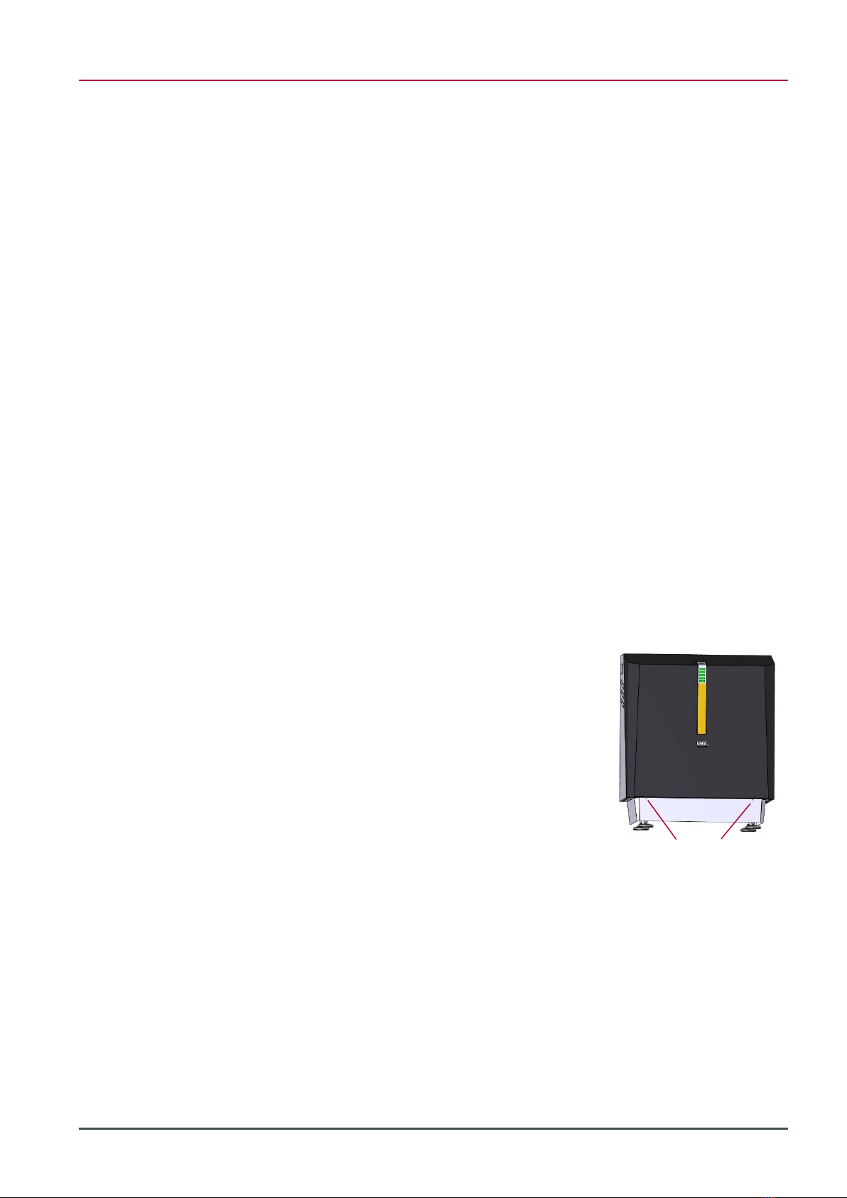
2.1.1 Overall view
2.1.2 Conformity
The following standards, laws and guidelines were taken into account during the
development of the modular battery:
EU directive with CE labelling obligation
Low Voltage Directive 2014/35/EU
EMC Directive 2014/30/ EU
Legal requirements
UN transport test (lithium systems)
Standards and user guidelines
DIN EN 60730
DIN EN 62619
Figure 1: Overall view of
battery system
Status display
SOC display
Implementation
for power cables
Implementation
for communication
DC disconnectors
adjustable base
detachable hood

2 Product description
V1.2 | 06/08/2020 Page 11 of 28
2.2 Scope of delivery
Hyperion system housing
Installation kit (in system housing) is included:
7 RJ45 patch cables A
12 screws M6x10 B
3 Dummy sockets, power plugs C
2 PG connections D
▪1 Three-hole cable bushing E
▪1 Single-hole cable bushing F
Installation instructions
3 to 6 Helios modular batteries
A B C D E F
2.3 Technical data
2.3.1 Performance features
Modules in series
3
4
5
6
Energy content (nom./usable)
9 kWh /
7.5 kWh
12 kWh /
10 kWh
15 kWh /
12.5 kWh
18 kWh /
15 kWh
Nominal voltage
155 V
207 V
258 V
310 V
End-of-charge voltage
172.5 V
230.0 V
287.5 V
345.0 V
Final discharge voltage
126 V
168 V
210 V
252 V
Capacity (nom.)
57 Ah
57 Ah
57 Ah
57 Ah
Charging current (max.)
30 A
30 A
30 A
30 A
Discharge current peak
40 A
40 A
40 A
40 A
Discharge power peak
6.2 kW
8.3 kW
10.3 kW
12.4 kW
Discharge capacity (max.)
4.6 kW
6.2 kW
7.7 kW
9.3 kW
Weight
107 kg
129 kg
151 kg
173 kg
Dimensions
(W x H x D)
751 mm x 870 mm x 423 mm
Discharge operating temperature
-20 to 55 °C
Load operating temperature
0 to 45 °C
Storage temperature
-20 to 60 °C
Battery chemistry
Li-ion NMC
Discharge depth
83 % DOD [in relation to nom. capacity]
Full Cycles
5,000 or 3,000 (for residual capacity of 60 % or 80 %)
2.3.2 Dimensions and weight of individual module
Dimensions (W x H x D): 545.2 mm x 214 mm x 155.4 mm
Weight: 22 kg
Figure 2: Installation kit
Table 3: Technical data

2 Product description
Page 12 of 28 Original installation instructions Hyperion Lithium Ion Energy Storage
2.3.3 Compatible inverters
SMA Sunny Boy Storage 3.7 / 5.0 / 6.0 (CAN)
COSTAL PLENTICORE plus (RS-485)
2.3.4 Supply, interfaces, connections
The battery system is supplied with the following connections:
+ DC cable: AWG8 red (American standard for wire cross section)
- DC cable: AWG8 black
Cable for grounding: AWG8 yellow-green
Communication cable, either CAN or RS-485
All cables are about 40 cm long.
NOTICE: When extending the power cables, do not exceed these lengths:
6 mm² cross section: 4,5 m
10 mm² cross section: 7,5 m
The modular battery has one socket which contains (+) and (-) as power contacts and
two RJ45 sockets which contain CAN bus and status and signal lines:
1 socket with power contacts (+) and (-)
1 RJ45 sockets with CAN bus connection for monitoring and control of
the modular battery by the higher-level controller (X1)
1 RJ45 socket for connecting a further modular battery (X2)
2 M6 threads for connecting the grounding
2.3.5 Ambient conditions
Operation exclusively inside buildings (air-conditioned and non-air-conditioned
interiors):
Temperature: 0 … 45 °C
Relative humidity: 5 ... 85 %
Height: 0 ... 2000 m above sea level
Temperature storage: -20 … 60 °C
Battery system
Modular battery
Operation
Storage

3 Commissioning
V1.2 | 06/08/2020 Page 13 of 28
2.4 Status and SOC display
During operation 6 LED fields indicate status and SOC of the battery system.
LED
10 seconds
Status
Green –on
Discharge mode
Green - flashes
(0,5 s on / 1 s off)
Ready (battery relay engaged - waiting for
charge or discharge)
Green –flahes slowly
(1 s on / 5 s off)
Standby (battery system relay open)
Blue - on
Charging mode
Blue - flashes
(0,5 s on / 1 s off)
Diagnosis or shutdown of the battery system
Blue - flahes slowly
(1 s on / 5 s off)
System start, relay test or software update
Red - flashes quickly
(0,2 s on / 0,2 s off)
System error - System has disconnected
battery from inverter
Red –flashes
(0,5 s on / 1 s off)
Error during start-up of the battery system -
battery remains disconnected
3Commissioning
3.1 Safety Instructions
The installation may only be carried out by qualified electricians according to IEC
60204-1 (International Electrotechnical Commission).
The housing including electronics weighs 43 kg. One modular battery weighs 22 kg.
Heavy lifting can cause a disturbance of the musculoskeletal system.
Lift the Hyperion cover (11 kg) and base (32 kg) separately.
If necessary, do not lift the Hyperion base alone or be sure to use
transport aids.
Risk of crushing and abrasions when lifting and inserting the modular batteries.
Use foot and hand protection.
3.2 Installation
3.2.1 Transport
If the installation site is difficult to access, it is recommended that the base and the
hood of the system housing be carried to the installation site separately:
1. Open the packaging of the Hyperion system housing.
2. Unscrew 2 screws (4 mm Allen key) at the front of the bottom of the
system housing.
3. Remove the hood from the system housing base.
4. Carry the hood and base to the installation site individually.
Table 4: Overview LED
status codes
Guidelines
Handling, transport
Installation site
difficult to access
3 Commissioning
Page 14 of 28 Original installation instructions Hyperion Lithium Ion Energy Storage
The modular batteries should be transported to the installation site in their original
packaging.
3.2.2 Choice of installation site
The battery system can be mounted upright on the floor or in a hanging position on
the wall.
It is recommended that the battery system be installed on the floor against a wall,
where the inverter can be mounted centrally above it. The inverter should be
mounted at least 20 cm above the battery system. At a distance of up to 30 cm, the
cables already attached to the Hyperion can be used.
Leave space of at least 30 cm free to the left and right of the battery system to get to
the DC disconnect switch to ensure sufficient air circulation.
To prevent the battery system from tipping over, it can be secured to the wall with
two screws (not supplied). Two fixing points are provided in the system housing for
this purpose.
Four fixing points are provided in the system housing for wall mounting. Since the
battery system can weigh up to 177 kg, it must be checked in advance whether the
wall and fastening material are suitable to support the load in the long term.
3.2.3 Mounting
The installation location for the battery system and the inverter have been
determined.
Recommended mounting:
5. Install the wall bracket of the inverter.
6. Hook the inverter into its bracket.
7. Unscrew the cover of the connection area.
8. If not already done, remove the cover
from the battery system housing:
Unscrew 2 screws (4 mm Allen key)
on the front underside.
Remove the cover from the base.
Position the base of the battery housing at the intended installation location (and
screw it on if necessary).
Modular batteries
Recommendation
Securing against
tipping over
Wall hanging
mounting
Requirement
Instructions
Screws M5

3 Commissioning
V1.2 | 06/08/2020 Page 15 of 28
3.3 Assembly
3.3.1 Installing Helios modular batteries
CAUTION
Risk of crushing due to improper installation.
Falling or improper insertion of the module can cause slight
bruising and abrasions to hands and feet.
Wear protective clothing.
CAUTION
Ergonomic hazards due to heavy lifting.
Lifting the modular battery can cause a disturbance of the
musculoskeletal system.
Should it be necessary, be sure not to lift the module
alone.
Use a lifting aid, when necessary.
ATTENTION
Incorrect installation due to damaged or contaminated modular batteries.
Only faultless modules may be mounted. The housing must be undamaged. The
contact points must be undamaged and clean.
Perform a visual inspection.
Clean the contact points with a dry cloth if necessary.
The modular battery may only be inserted into the Hyperion battery system provided
for this purpose.
✓The power storage system is securely installed.
✓The main switch of the power storage system is off.
✓The modular batteries must have a similar voltage.
Safety Instructions
Requirement

3 Commissioning
Page 16 of 28 Original installation instructions Hyperion Lithium Ion Energy Storage
1. Make sure that the DC disconnector of the Hyperion is set to "off".
2. Loosen the two screws Hand I, with which the downholder is fixed on
the left and right, and lift up the downholder.
3. Unpack and insert the modular batteries.
NOTICE: To ensure the best possible cooling; we recommend that the
modular batteries are inserted as in Figure 3.
With 3 Helios modular batteries
With 4 Helios modular batteries
With 5 Helios modular batteries
With 6 Helios modular batteries
4. Screw the downholder to the right and left of the base of the system
housing.
5. Screw each modular battery with two screws (M6) to the
downholder/grounding support.
For example, refer to Figure 4.
Instructions
Figure 3: Insert 3 to 6
Helios modular batteries
I
H
3 Commissioning
V1.2 | 06/08/2020 Page 17 of 28
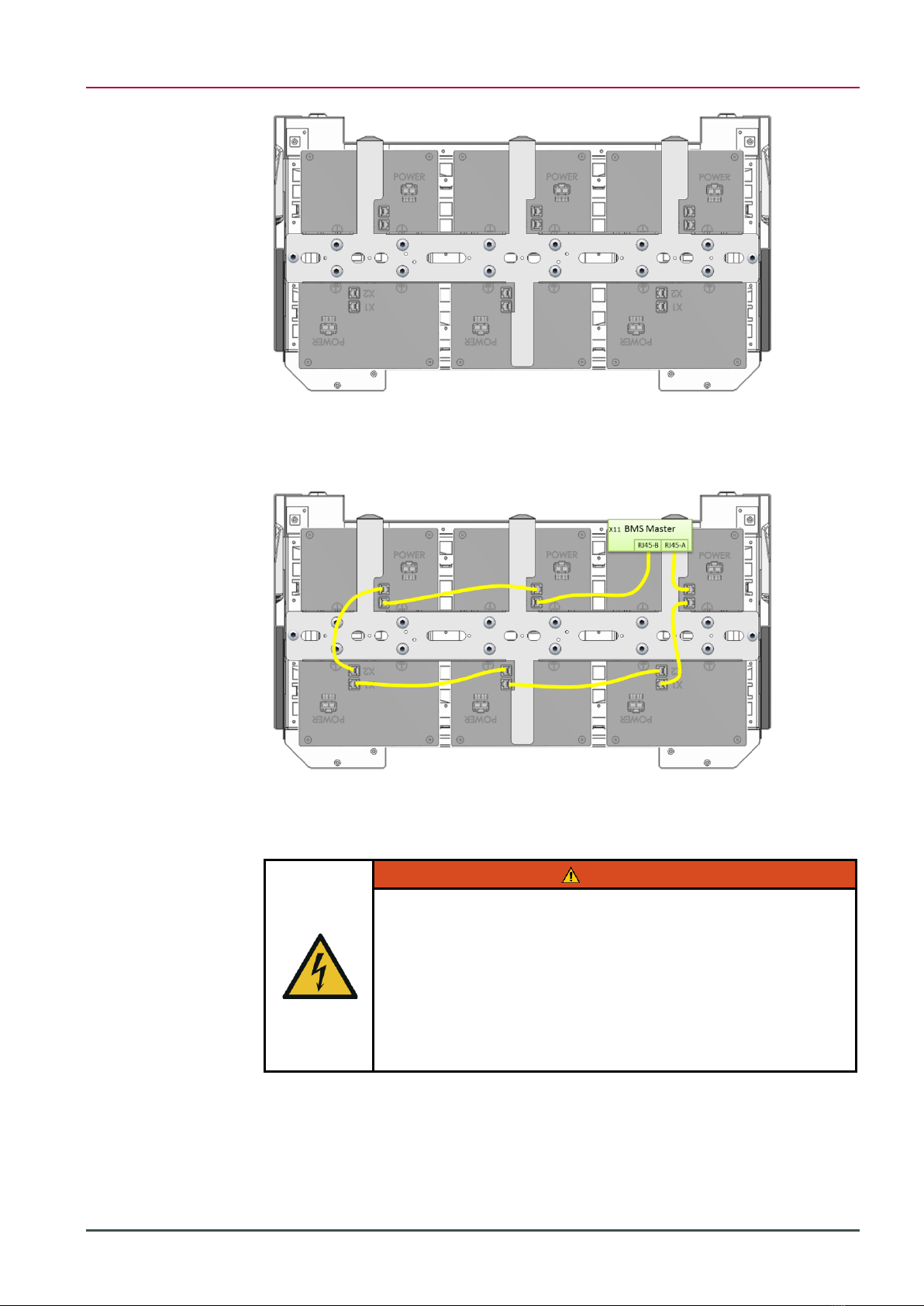
6. Use the patch cables to connect the BMS master (left of the two RJ45
sockets) with the installed modular batteries.
For example, refer to Figure 5.
7. Connect the last module with the master’s left RJ45 socket (RJ45-B).
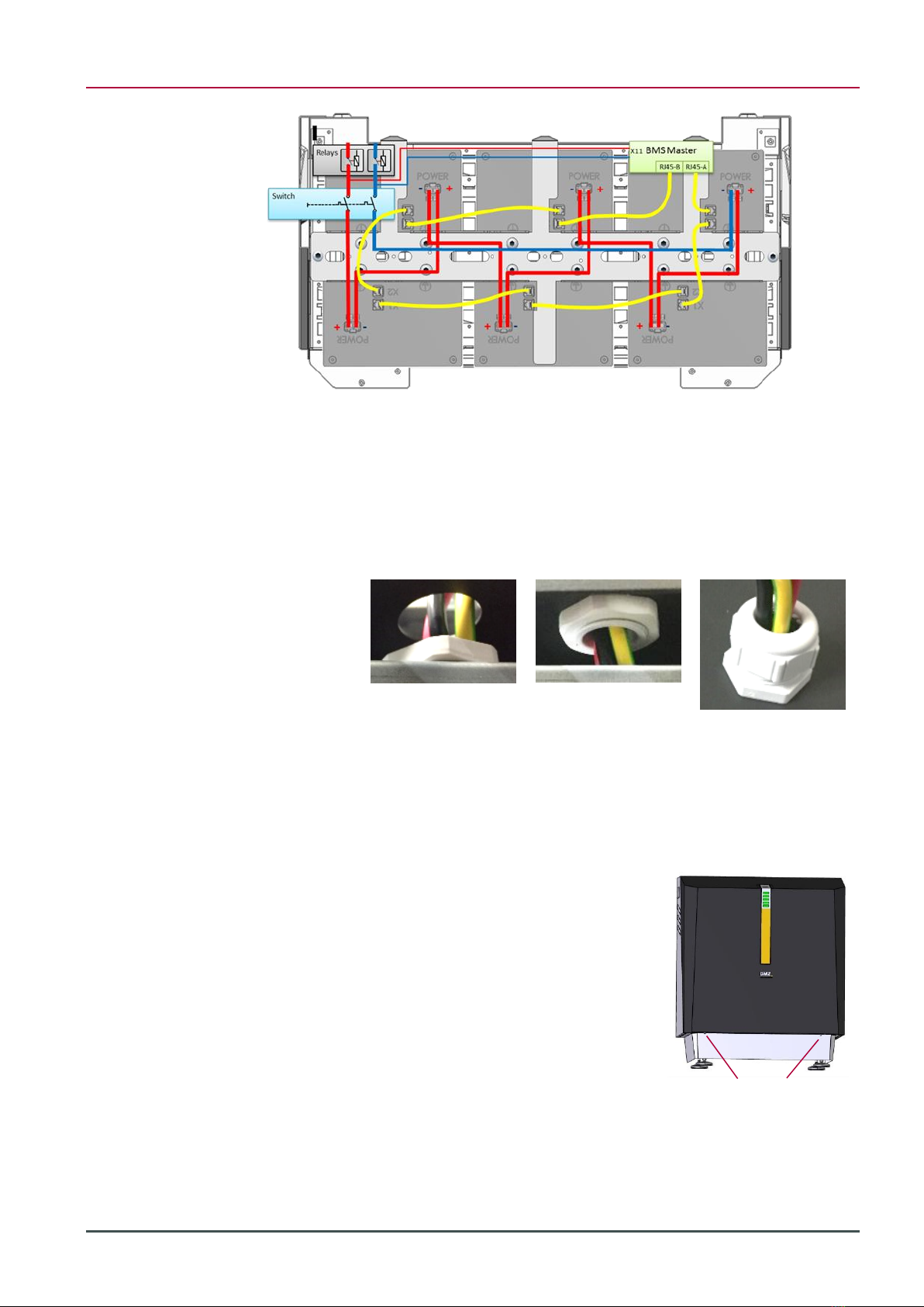
3.3.2 Connect Helios modular batteries next to each other in series
WARNING
Electric shock from live parts.
Touching live components may cause electrical shock, which may
create intense heat or paralyse muscles. The latter can lead to
ventricular fibrillation, cardiac arrest or respiratory paralysis, or
death.
Never touch the contacts.
1. Remove the safety cover of the "Power" sockets.
2. Insert the power plug for the respective modular battery until it clicks
into place. For example, refer to Figure 6.
Figure 4: Modular
batteries fixed to the
grounding support
Figure 5: Connecting the
modules to the BMS
master with patch cables
X1
X2
X1
X2
X1
X2
X2
X1
X2
X1
X2
X1
3 Commissioning
Page 18 of 28 Original installation instructions Hyperion Lithium Ion Energy Storage
3. Check by pulling the power plugs to make sure that the latching is
engaged.
4. If there are less than 6 modular batteries: fit the power plugs not
required with the dummy sockets Csupplied.
5. Feed the power cables (red and black) as well as PE (yellow-green)
through the left hole in the basic housing and fix them with the
supplied PG screw connection.
NOTE First lead the cables through the union nut of the PG gland and
then through the outer housing.
6. Lead the communication cable through the right hole and fix it with the
supplied cable gland.
3.3.3 Closing the housing of the battery system
1. Position the housing hood (with display) in
front of the housing base and plug the
cable for the display on the board into the
hood.
2. Insert the hood into the guide at the top
and close it at the bottom with the two
M5x10 screws (4 mm Allen key) which
were unscrewed in 3.2.3.
Figure 6: Power path
with switching devices
and BMS
Screws M5
3 Commissioning
V1.2 | 06/08/2020 Page 19 of 28
3.3.4 Adding battery modules
3. Check the voltage of the new modules. The
voltage should be between 46 V and 56 V.
4. Adjust the voltage of the battery system to ±1 V
to the voltage of the new modules (see Appendix
8.3). An exactly adjusted module voltage avoids
adjustment in the system and allows immediate
access to the full capacity.
5. Disconnect the inverter from voltage and switch off Hyperion.
6. Install the new modules. See chapter 3.3 Assembly.
7. Put the system into operation. See chapter 3.4.
3.3.5 Disposal
Dispose of transport packaging for recycling in accordance with the statutory
provisions.
It is recommended to keep not required parts (patch cables, dummy plugs, screws)
together with the installation instructions near the battery system.
Before removing defective modular batteries, the power socket must be taped with
insulating tape after removing the power plug.
3.4 Connecting the inverter
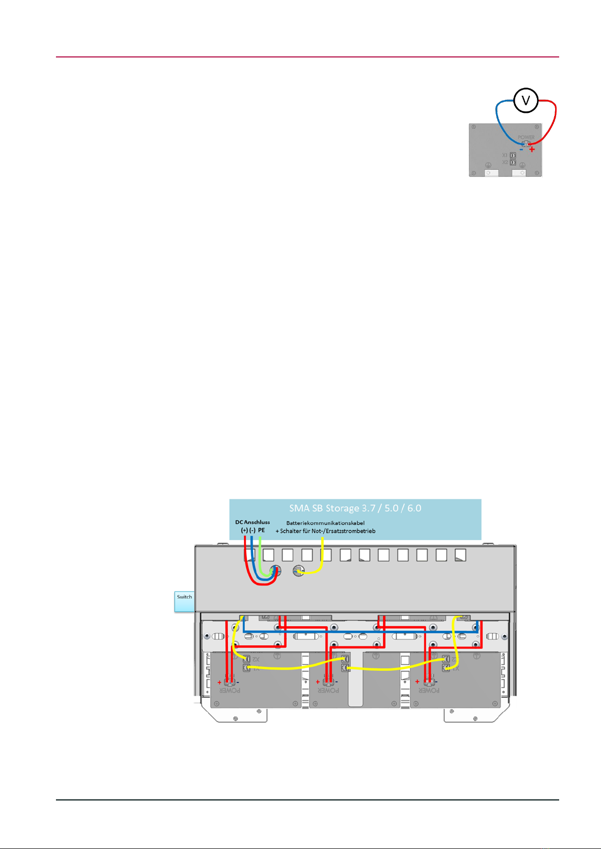
3.4.1 SMA Sunny Boy Storage 3.7 / 5.0 / 6.0
1. Feed the DC power cable, PE as well as the communication cable(s)
through the respective PG screw glands into the connection
compartment of the inverter.
2. Connect the cables in the inverter according to the Sunny Boy Storage
3.7 / 5.0 / 6.0 operating instructions.
Instructions
Figure 7: Connecting the
SMA SB Storage to the
BMZ Hyperion
3 Commissioning
Page 20 of 28 Original installation instructions Hyperion Lithium Ion Energy Storage
Chapter 6.5: Connecting battery communication cable:
▪yellow: CAN H (E)
▪white: CAN L (D)
▪red: Enable (B)
▪black: GND (C)
Chapter 6.1.2: Interior View
▪Yellow-green grounding point for grounding the battery (L)
Chap. 6.8 DC connection
▪Red (+) (A+)
▪Black (-) (A-)
It is recommended to use all bridges (30 A)
3. Check all electrical connections
4. Close the housing of the inverter.
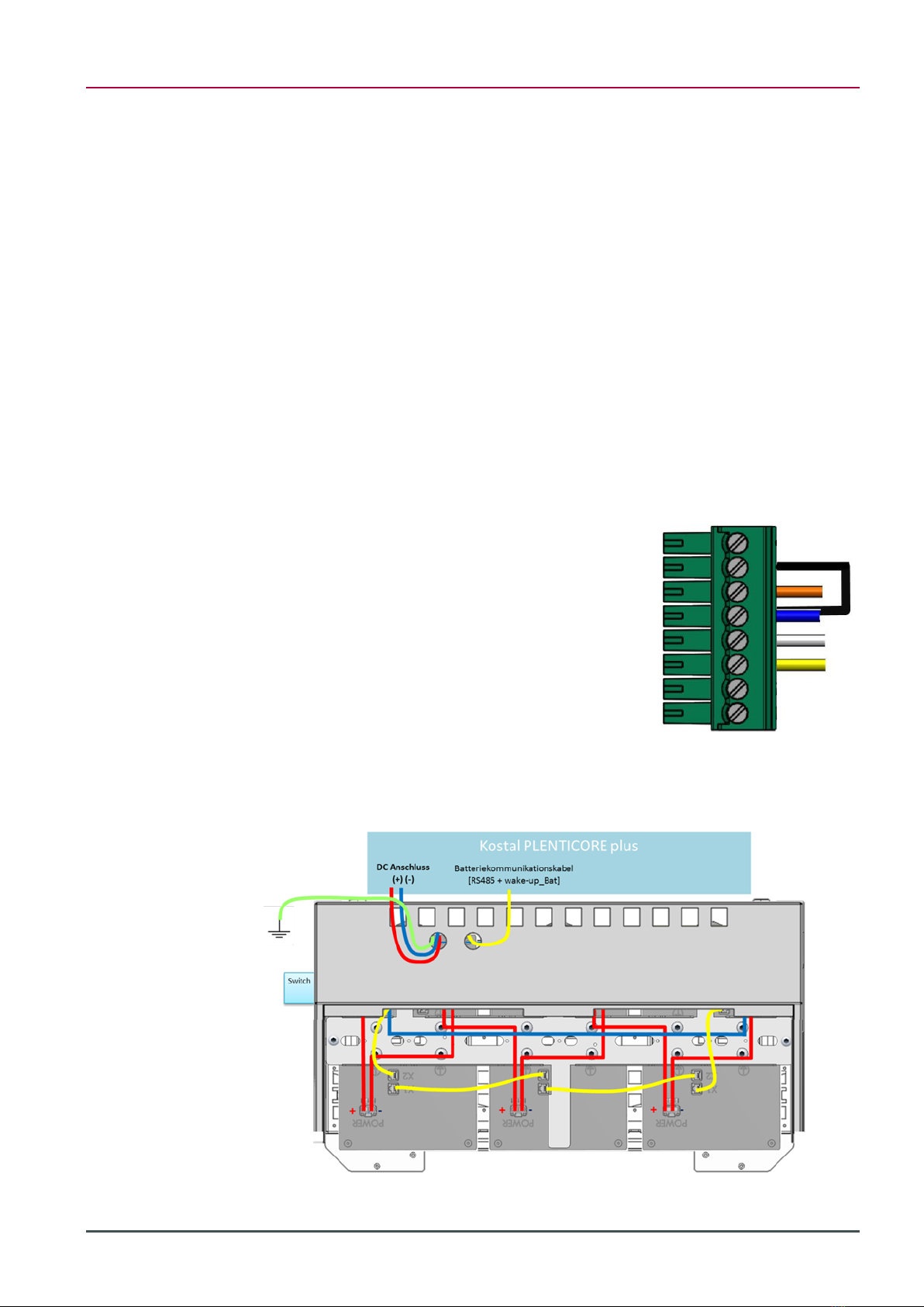
3.4.2 Kostal PLENTICORE plus
1. In order to operate the Hyperion storage system communicatively with
the Kostal PLENTICORE plus, the communication must be switched to
RS485.
Disconnect the X2 plug from the
BMS master (green plug at top left).
Pin the yellow wire from PIN1 to
PIN3 (RS485+).
Pin the white wire from PIN2 to
PIN4 (RS485-).
Bridge PIN7 and PIN8 to activate
the RS485 communication.
Plug X2 back into BMS master.
2. Preparation: Ground the Hyperion housing:
PE
▪Yellow-green Connect to grounding rail
Figure 8: Connecting the
PLENTICORE plus to the
BMZ Hyperion
Table of contents
Other BMZ Camera Accessories manuals


