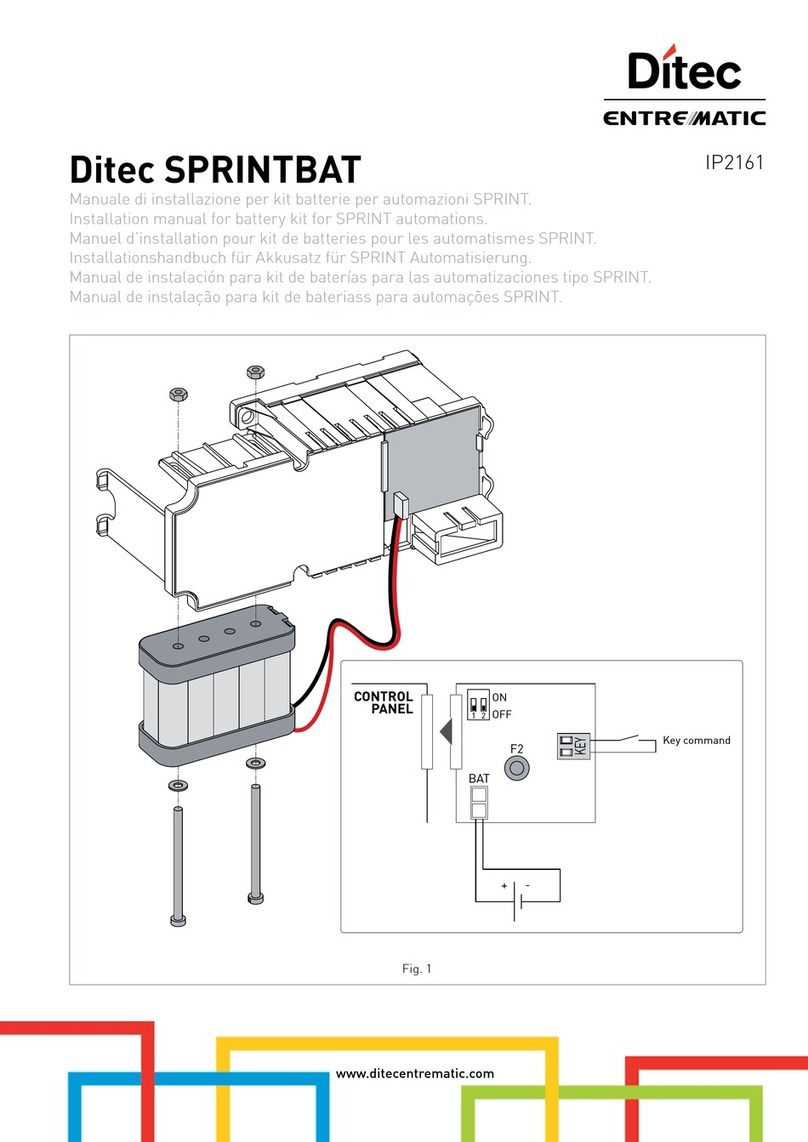
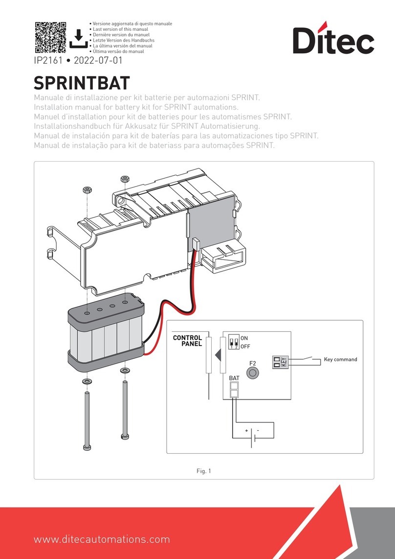
DITEC DAB905BAT User manual

DAB905ESE
FUSE 5AT/250V (4x)
Funzione sull’unità di estensione DAB905ESE;
Modalità interruzione di corrente con batterie di backup installate.
- Sono disponibili due contatti per il collegamento di batterie da 12 V (NiMH).
- Le batterie sono ricaricabili e sono caricate dall’unità di controllo nell’apriporta.
- Un dip-switch è disponibile per il monitoraggio delle batterie (DIP5). Il LED sul quadro di comando indica la batteria guasta.
Se selezionato, il relè sull’unità DAB905ESA può fornire informazioni di batteria guasta.
La capacità della batteria viene testata dopo l’accensione e una volta alla settimana. La tensione della batteria viene continuamente controllata.
L’apriporta può funzionare in due diverse modalità: modalità RISPARMIO ENERGETICO e modalità CONTINUITÀ
- In modalità RISPARMIO ENERGETICO, in assenza di tensione di rete, l’apriporta completa il ciclo operativo in corso e quindi interrompe l’alimen-
tazione dalla batteria.
L’apriporta alimentato a batteria può essere riattivato per eseguire un nuovo ciclo operativo con un impulso a chiave (KEY). In questa modalità,
l’apriporta può restare in stand-by fino a 1 settimana, in attesa dell’impulso a chiave.
- In questa modalità, per porte doppie, solo l’operatore master necessita di una batteria e di una scheda DAB905ESE
- In modalità CONTINUITÀ, in assenza di tensione di rete, l’apriporta funziona normalmente finché le batterie non si scaricano.
- Batterie nuove e completamente cariche possono, di norma, aprire e chiudere una porta per un massimo di 300 volte in modalità CONTINUITÀ.
- In questa modalità, per porte doppie, entrambe gli operatori necessitano di una batteria e di una scheda DAB905ESE.
I sensori seguenti non sono attivi durante il funzionamento a batteria in modalità RISPARMIO ENERGETICO;
- Tappetino
- Rilevatore presenza (OPD).
- Sensore di sicurezza di inversione lato interno (installato sulla porta)
- Sensore di sicurezza in apertura lato esterno (installato sulla porta)
NOTA: Tutti i sensori funzionano normalmente in modalità CONTINUITÀ.
In modalita RISPARMIO ENERGETICO, su automazioni collegate in parallelo, collegare le batterie alla sola automazione MASTER equipaggiata con
DAB905ESE.
Impostazioni per porte a due ante:
Funzione Impostazione su
MASTER SLAVE
Selezione della modalità di utilizzo delle batterie durante il funzionamento con alimentazione a batterie X
Indicazione errore sul quadro di comando.
Frequenza di lampeggiamento LED Causa Rimedio
Due lampeggi da 0,3 secondi, pausa, ecc. Batteria difettosa Sostituire la batteria (funzionamento normale con alimentazione di rete)
DAB905ESE
FUSE 5AT/250V (2x)
DAB905BAT
DAB905BAT2
DAB905BAT / DAB905BAT2
Manuale di installazione kit batterie
Installation manual battery backup unit
www.ditecautomations.com
• Versione aggiornata di questo manuale
• Last version of this manual
ITALIANO
IP2182 • 2022-09-01

2
IP2182
Selezione modalità batteria cambiando il gruppo parametri configurato:
1. Scollegare l’alimentazione di rete e le batterie.
2. Premere e mantenere premuto il pulsante di apprendimento (LRN).
3. Dare alimentazione di rete, il LED si accende ( ).
4. Rilasciare il pulsante LRN dopo 2 lampeggi (il LED si spegne).
5. Il LED lampeggia tante volte quante quelle corrispondenti al numero di gruppo di parametri (vedi tabella).
6. Premere il tasto LRN per passare al gruppo di parametri successivo a quello impostato. Raggiunto il limite massimo di parametri, si ricomincia
dal numero 1.
7. Premere il tasto LRN finché si imposta il gruppo di parametri desiderato.
8. Scollegare l’alimentazione di rete.
9. Al successivo collegamento di rete, l’automazione userà il nuovo gruppo di parametri.
Gruppo
Parametro
1
(default)
2345678910
Tempo porta
aperta contatto 3-5
scheda ESE (a)
15 min infinito 15 min 15 min 15 min 15 min 15 min 15 min 15 min 15 min
Uso batteria Risparmio
energetico
Risparmio
energetico Continuità Risparmio
energetico
Risparmio
energetico
Risparmio
energetico
Risparmio
energetico
Risparmio
energetico
Risparmio
energetico Continuità
Modalità blocco con
comando KILL attivo Bloccato Bloccato Bloccato
Blocco
gestito dal
selettore
Bloccato Bloccato Bloccato Bloccato
Blocco
gestito dal
selettore
Bloccato
Ostacolo in
chiusura (b) Chiusura Chiusura Chisura Chiusura Inversione Chiusura Chiusura Chiusura Chiusura Inversione
Modalità sensore di
presenza installato
su porte sincroniz-
zate. (c)
Rilevamento
separato
Rilevamento
separato
Rilevamento
separato
Rilevamento
separato
Rilevamento
separato
Rilevamento
comune
Rilevamento
separato
Rilevamento
separato
Rilevamento
separato
Rilevamento
separato
Tentativo blocco in
chiusura (d) Abilitato Abilitato Abilitato Abilitato Abilitato Abilitato Disabilitato Abilitato Abilitato Abilitato
Comando O/C
apertura/chiusura
(e) modalità
BIDIREZIO-
NALE
modalità
BIDIREZIO-
NALE
modalità
BIDIREZIO-
NALE
modalità
BIDIREZIO-
NALE
modalità
BIDIREZIO-
NALE
modalità
BIDIREZIO-
NALE
modalità
BIDIREZIO-
NALE
modalità BI-
DIREZIONA-
LE / PORTA
CHIUSA /
MONODIRE-
ZIONALE
modalità
BIDIREZIO-
NALE
modalità
BIDIREZIO-
NALE
Configurazione
contatto chiusura di
emergenza (KILL)
N.O. N.O. N.O. N.O. N.O. N.O. N.O. N.O. N.C. N.O.
NOTE:
(a) Se la porta rimane aperta, a seguito di un comando apre O/C, dopo 15 min di inattività, il quadro elettronico avvia un comando di chiusura.
(b) Se impostato in modalità “CHIUSURA” in presenza di un ostacolo l’automazione si ferma.
Se impostato in modalità “INVERSIONE”, l’automazione riapre. Ritenta la chiusura finché l’ostacolo viene rimosso.
Con parametri impostati su 1 (impostazione di fabbrica), durante la fase di chiusura, se interviene un problema con l’aggancio del blocco, la porta
ritenta l’aggancio ulteriormente due volte in modo automatico, e una volta in più in modo manuale. Questa funzione può essere disabilitata (vedi
Parametro 7).
(c) Nel caso di porte sincronizzate il sensore di rilevamento può intervenire indipendentemente su ogni porta o contemporaneamente.
(d) Durante la fase di chiusura, se interviene un problema con l’aggancio del blocco, la porta richiude e ritenta l’aggancio.
(e) Con interruttore ON/OFF/HOLD il comando O/C è sempre attivo. Tranne nella posizione HOLD - Porta aperta.
Con selettore di programmi il comando O/C funziona normalmente in modalità BIDIREZIONALE.
Con parametro 8 selezionato, il comando O/C funziona in modalità BIDIREZIONALE / MONODIREZIONALE / PORTA CHIUSA.
DAB105
Contatore tempo installazione batteria, disponibile solo su DAB205
Un contatore invia un avviso al dispositivo di monitoraggio delle batterie
quando le batterie raggiungono i due anni di vita. Per azzerare il contatore
in modalità CONTINUITÀ, interrompere l’alimentazione di rete e premere
il pulsante LEARN. In modalità alimentazione a batteria tutte le altre funzioni
del pulsante LEARN sono disattivate.
In modalità POWER SAVE, inviare un impulso a chiave, quindi premere il
pulsante LEARN quando il sistema è avviato. Il dip-switch di monitoraggio
della batteria deve essere in posizione ON.
LRN
PAG
1
ON
POAS HOTCLTQ KHOT
1
ON
2345
Battery monitoring (ON)
12 3
1
ON
2345
ITALIANO

3
IP2182
DAB205
Gruppo
Parametro
1
(impostazione
di fabbrica)
2345678910111213141516
Tempo porta
aperta contatto
3-5 scheda ESE (a)
15 min infinito 15 min 15 min 15 min 15 min 15 min 15 min 15 min 15 min 15 min 15 min 15 min 15 min infinito infinito
Uso batteria Risparmio
energetico
Risparmio
energetico Continuità Risparmio
energetico
Risparmio
energetico
Risparmio
energetico
Risparmio
energetico
Risparmio
energetico
Risparmio
energetico Continuità Risparmio
energetico
Risparmio
energetico
Risparmio
energetico
Risparmio
energetico Continuità Continuità
Modalità blocco con
comando KILL attivo Bloccato Bloccato Bloccato
Blocco
gestito dal
selettore
Bloccato Bloccato Bloccato Bloccato
Blocco
gestito dal
selettore (*)
Bloccato Sbloccato Sbloccato Bloccato Sbloccato Bloccato Bloccato
Ostacolo in
chiusura (b) Chiusura Chiusura Chisura Chiusura Inversione Chiusura Chiusura Chiusura Chiusura Inversione Chiusura Chiusura Chiusura Chiusura Inversione Inversione
Modalità sensore di
presenza installato
su porte sincroniz-
zate. (c)
Rilevamento
separato
Rilevamento
separato
Rilevamento
separato
Rilevamento
separato
Rilevamento
separato
Rilevamento
comune (**)
Rilevamento
separato
Rilevamento
separato
Rilevamento
separato
Rilevamento
separato
Rilevamento
separato
Rilevamento
separato
Rilevamento
separato
Rilevamento
separato
Rilevamento
separato
Rilevamento
separato
Tentativo blocco in
chiusura (d) Abilitato Abilitato Abilitato Abilitato Abilitato Abilitato Disabilitato Abilitato Abilitato Abilitato Abilitato Abilitato Abilitato Abilitato Abilitato Abilitato
Comando O/C
apertura/chiusura
(e) modalità
BIDIREZIO-
NALE
modalità
BIDIREZIO-
NALE
modalità
BIDIREZIO-
NALE
modalità
BIDIREZIO-
NALE
modalità
BIDIREZIO-
NALE
modalità
BIDIREZIO-
NALE
modalità
BIDIREZIO-
NALE
modalità BI-
DIREZIONA-
LE / PORTA
CHIUSA /
MONODI-
REZIONALE
modalità
BIDIREZIO-
NALE
modalità
BIDIREZIO-
NALE
modalità
BIDIREZIO-
NALE
modalità
BIDIREZIO-
NALE
modalità
BIDIREZIO-
NALE
modalità
BIDIREZIO-
NALE
modalità BI-
DIREZIONA-
LE / PORTA
CHIUSA /
MONODI-
REZIONALE
modalità BI-
DIREZIONA-
LE / PORTA
CHIUSA /
MONODI-
REZIONALE
Configurazione
contatto chiusura di
emergenza (KILL)
N.O. N.O. N.O. N.O. N.O. N.O. N.O. N.O. N.C.
Monitorato N.O. N.O. N.C.
Monitorato
N.C.
Monitorato
N.C.
Monitorato N.O. N.C.
Monitorato
Contatto relè COM-
NO-NC (scheda
ESA) (d) Indicazione
errore
Indicazione
errore
Indicazione
errore
Indicazione
errore
Indicazione
errore
Indicazione
errore
Indicazione
errore
Indicazione
errore
Indicazione
errore
Indicazione
errore
Uscita KILL
in parallelo
ad altre
porte
Uscita KILL
in parallelo
ad altre
porte
Uscita KILL
in parallelo
ad altre
porte
Collega-
mento
blocco con
alimentazio-
ne diversa
da12/24 V
Collega-
mento
blocco con
alimentazio-
ne diversa
da12/24 V
Collega-
mento
blocco con
alimentazio-
ne diversa
da12/24 V
NOTE:
(*) Il blocco si sgancia durante un comando KILL in modalità apertura monodirezionale.
(a) Se la porta rimane aperta, a seguito di un comando apre O/C, dopo 15 min di inattività, il quadro elettronico avvia un comando di chiusura.
(b) Se impostato in modalità “CHIUSURA” in presenza di un ostacolo l’automazione si ferma.
Se impostato in modalità “INVERSIONE”, l’automazione riapre. Ritenta la chiusura finché l’ostacolo viene rimosso.
(c) Nel caso di porte sincronizzate il sensore di rilevamento può intervenire indipendentemente su ogni porta o contemporaneamente.
(**) Tenere presente che l’uso del Push and Go unitamente a questo parametro potrebbe causare interruzioni nel traffico pedonale.
(d) Nelle automazioni in parallelo, nell’automazione SLAVE questo parametro funzionerà come impostato dal gruppo parametri per la porta SLAVE, senza tenere in considerazione la configurazione impostata sulla
porta MASTER.
Con parametri impostati su 1 (impostazione di fabbrica, durante la fase di chiusura, se interviene un problema con l’aggancio del blocco, la porta ritenta l’aggancio ulteriormente due volte in modo automatico, e una
volta in più in modo manuale. Questa funzione può essere disabilitata (vedi Parametro 7) e nelle automazioni in parallelo, la porta SLAVE deve essere configurata separatamente)
(e) Con interruttore ON/OFF/HOLD il comando O/C è sempre attivo. Tranne nella posizione HOLD - Porta aperta.
Con selettore di programmi il comando O/C funziona normalmente in modalità BIDIREZIONALE.
Con parametro 8 selezionato, il comando O/C funziona in modalità BIDIREZIONALE / MONODIREZIONALE / PORTA CHIUSA.
ITALIANO

4
IP2182
ENGLISH
Function on the extension unit DAB905ESE;
Power failure mode with backup batteries installed.
- Two contacts are available for connection of 12 V batteries (NiMH).
- The batteries are rechargeable and will be charged by the control unit in the operator.
- DIP-switch for monitoring of batteries is also available (DIP5). Faulty battery will be indicated by the LED on the control panel.
If selected the relay on DAB905ESA can give a contact information. The capacity of the battery is tested after power on and once a week. The battery
voltage is continuously checked.
There are two different modes where the operator works; ENERGY SAVING mode and CONTINUITY mode.
- During ENERGY SAVING mode, with the mains power supply off, the operator will finish the actual operating cycle and then switch OFF the battery supply.
The battery powered operator can be reactivated to achieve a new operating cycle by an impulse on the KEY input. In power save mode the operator can
stand-by for up to 1 week, waiting for KEY impulse. In this mode, for double doors, only the master operator needs a battery and an DAB905ESE board.
- During CONTINUITY mode, with the mains power supply off, the operator will work as normal until the batteries are discharged. In this mode, for
double doors, both operators need to have batteries and DAB90ESE board.
- New, fully charged batteries can typically open and close a door max. 300 times in CONTINUITY mode.
The following sensors are not active in ENERGY SAVING mode during battery operation;
- Mat
- OPD presence detector.
- Presence impulse approach, door mounted.
- Presence detection swingpath, door mounted.
NOTE! All sensors works normally in CONTINUITY mode.
Settings for double doors.
Function Setting on the
MASTER SLAVE
Selection of the battery operating mode during operation on battery power X
Error indication
LED flash frequency on the control panel Reason Remedy
Two 0,3 s flashes, pause etc. Battery defective Replace battery (normal operation with mains power
Battery life counter, available only on DAB205
A battery counter sends a warning to the battery monitor when the batteries
are two years old. To reset the counter in CONTINUITY mode, cut the
main power and press the LEARN-button. All other LEARN-button functionality
is disabled in battery mode.
In ENERGY SAVING, make a key impulse and press the LEARN-button when
the system has started. The battery monitoring DIP switch needs to be in
position ON.
Select battery mode by changing group of parameter
1. Disconnect the battery and mains.
2. Press the Learn Button (LRN) and keep it depressed.
3. Connect the electrical power supply, the LED will light up ( ).
4. Release the LRN button after 2 flashes (the LED will switch off)
5. The LED flashes a number of short flashes that corresponds to the parameter group number (see table).
6. Press the LRN button to pass to the next group of parameters after the set one. When you have reached the maximum limit of the parameters,
you will restart from number 1.
7. Press the LRN button until you reach the required group of parameters.
8. Disconnect the mains power supply.
9. When the mains power supply is reconnected, the automation will use the new group of parameters.
LRN
PAG
1
ON
POAS HOTCLTQ KHOT
1
ON
2345
Battery monitoring (ON)
12 3
1
ON
2345
Parameter
group
1
(default) 23 4 567 8 9 10
Time of door open con-
tact 3-5 ESE card (a)
15 min infinito 15 min 15 min 15 min 15 min 15 min 15 min 15 min 15 min
Battery use Energy
savings Energy
savings Continuity Energy
savings Energy
savings Energy
savings Energy
savings Energy
savings Energy
savings Continuity
Block mode with KILL
command active Blocked Blocked Blocked
Block managed
by selector
Blocked Blocked Blocked Blocked Block anaged
by selector Blocked
Obstacle during clo-
sure (b) Closure Closure Closure Closure Reversal Closure Closure Closure Closure Reversal
Motion sensor installed
on synchronised doors. (c)
Separate
detection Separate
detection Separate
detection Separate
detection Separate
detection Common
Limit Separate
detection Separate
detection Separate
detection Separate
detection
Block attempt on
closure (d) Enabled Enabled Enabled Enabled Enabled Enabled Disabled Enabled Enabled Enabled
O/C command ope-
ning/closing (e) TWO-WAY
mode TWO-WAY
mode TWO-WAY
mode TWO-WAY
mode TWO-WAY
mode TWO-WAY
mode TWO-WAY
mode
TWO-WAY /
DOOR CLOSED /
ONE-WAY mode
TWO-WAY
mode TWO-WAY
mode
Configuration of
emergency closure
contact (KILL)
N.O. N.O. N.O. N.O. N.O. N.O. N.O. N.O. N.C. N.O.
NOTES:
a. If the door stays open following an O/C open command, the control panel will launch a closure command after 15 minutes of inactivity.
b. If set in “CLOSURE” mode, the automation will stop if an obstacle is detected. If set in “REVERSAL” mode, the automation will re-open. It continues to attempt the closure operation until the obstacle is removed. With parameters set on 1
(factory setting), if there is a problem with block coupling during the closure phase, the door will attempt to enable the coupling twice in automatic mode, then once more in manual mode. This function can be disabled (see Parameter 7).
c. In the case of synchronised doors, the motion sensor can intervene independently on each door, or simultaneously.
d. If there is a problem with block coupling during the closure phase, the door will again close and attempt to enable the coupling.
e. With the ON/OFF/HOLD switch, the O/C command is always active except in the “HOLD - Door open” position. With the program selector, the O/C command usually functions in TWO-WAY
mode. With Parameter 8 selected, the O/C command functions in TWO-WAY / ONE-WAY / DOOR CLOSED mode.
DAB105

5
IP2182
DAB205
NOTES:
(*) The block is released during a KILL command in one-way opening mode.
(a) If the door stays open following an O/C open command, after 15 min of inactivity the control panel will launch a closure command.
(b) If set in “CLOSURE” mode, the automation will stop if an obstacle is detected.
If set in “REVERSAL” mode, the automation will re-open. It continues to attempt the closure operation until the obstacle is removed.
(c) In the case of synchronised doors, the motion sensor can intervene independently on each door, or simultaneously.
(**) Bear in mind that the use of Push and Go together with this parameter could cause interruptions to pedestrian access.
(d) In parallel automations, this parameter will act on the SLAVE automation as set by the parameter group for the SLAVE door, without taking into consideration the configuration set on the MASTER door.
With parameters set on 1 (factory setting), if there is a problem with block coupling during the closure phase, the door will attempt to enable the coupling twice in automatic mode, then once more in manual mode.
This function can be disabled (see Parameter 7) and, in the parallel automations, the SLAVE door must be configured separately).
(e) With the ON/OFF/HOLD switch, the O/C command is always active, except in the "HOLD - Door open" position.
With the program selector, the O/C command usually functions in TWO-WAY mode.
With Parameter 8 selected, the O/C command functions in TWO-WAY / ONE-WAY / DOOR CLOSED mode.
Parameter
group
1
(factory
setting)
2345678910111213141516
Time of door
open contact
3-5 ESE card (a)
15 min endless 15 min 15 min 15 min 15 min 15 min 15 min 15 min 15 min 15 min 15 min 15 min 15 min endless endless
Battery use Energy
savings
Energy
savings Continuity Energy
savings
Energy
savings
Energy
savings
Energy
savings
Energy
savings
Energy
savings Continuity Energy
savings
Energy
savings
Energy
savings
Energy
savings Continuity Continuity
Block mode with
KILL command
active
Blocked Blocked Blocked
Block ma-
naged by
selector
Blocked Blocked Blocked Blocked
Block ma-
naged by
selector (*)
Blocked Released Released Blocked Released Blocked Blocked
Obstacle during
closure (b) Closure Closure Closure Closure Reversal Closure Closure Closure Closure Reversal Closure Closure Closure Closure Reversal Reversal
Motion sensor in-
stalled on synchro-
nised doors. (c)
Separate
detection
Separate
detection
Separate
detection
Separate
detection
Separate
detection
Common
detection
(**)
Separate
detection
Separate
detection
Separate
detection
Separate
detection
Separate
detection
Separate
detection
Separate
detection
Separate
detection
Separate
detection
Separate
detection
Block attempt on
closure (d) Enabled Enabled Enabled Enabled Enabled Enabled Disabled Enabled Enabled Enabled Enabled Enabled Enabled Enabled Enabled Enabled
O/C command
opening/closing
(e)
TWO-WAY
mode
TWO-WAY
mode
TWO-WAY
mode
TWO-WAY
mode
TWO-WAY
mode
TWO-WAY
mode
TWO-WAY
mode
TWO-WAY
/ DOOR
CLOSED /
ONE-WAY
mode
TWO-WAY
mode
TWO-WAY
mode
TWO-WAY
mode
TWO-WAY
mode
TWO-WAY
mode
TWO-WAY
mode
TWO-WAY
/ DOOR
CLOSED /
ONE-WAY
mode
TWO-WAY
/ DOOR
CLOSED /
ONE-WAY
mode
Configuration of
emergency closure
contact (KILL)
NO NO NO NO NO NO NO NO NC
Monitored NO NO NC
Monitored
NC
Monitored
NC
Monitored NO NC
Monitored
COM-NO-NC relay
contact (ESA card)
(d) Error indi-
cation
Error indi-
cation
Error indi-
cation
Error indi-
cation
Error indi-
cation
Error indi-
cation
Error indi-
cation
Error indi-
cation
Error indi-
cation
Error indi-
cation
KILL output
in parallel
with other
doors
KILL output
in parallel
with other
doors
KILL output
in parallel
with other
doors
Block
connection
with power
supply
other than
12/24 V
Block
connection
with power
supply
other than
12/24 V
Block
connection
with power
supply
other than
12/24 V

ASSA ABLOY Entrance Systems AB
Lodjursgatan 10
SE-261 44, Landskrona
Sweden
© ASSA ABLOY
IP2182
AVVERTENZE GENERALI PER LA SICUREZZA
• Conservate le presenti istruzioni per futuri riferimenti.
• L’installazione, i collegamenti elettrici e le regolazioni devono essere effettuati da personale tecnico qualificato nell’osservanza della Buona Tec-
nica e in ottemperanza alle norme vigenti.
• Questo prodotto dovrà essere destinato solo all’uso per il quale è stato espressamente concepito. Ogni altro uso è da considerarsi improprio e quindi
pericoloso. Il costruttore non può essere considerato responsabile per eventuali danni causati da usi impropri, erronei ed irragionevoli.
• Leggere attentamente le istruzioni prima di iniziare l’installazione del prodotto. Una errata installazione può essere fonte di pericolo.
• Prima di iniziare l’installazione verificare l’integrità del prodotto.
• Non installare il prodotto in ambiente e atmosfera esplosivi: presenza di gas o fumi infiammabili costituiscono un grave pericolo per la sicurezza.
• Pericolo di esplosione se la batteria viene sostituita con una di tipo non corretto.
I materiali dell’imballaggio (plastica, polistirolo, ecc.) non vanno dispersi nell’ambiente e non devono essere lasciati alla portata dei bambini
in quanto potenziali fonti di pericolo.
GENERAL SAFETY PRECAUTIONS
• Keep these instructions for future reference.
• Installation, electrical connections and adjustments must be performed by qualified personnel in accordance with Good Working Methods and in
compliance with the current standards.
• This product must only be used for the specific purpose for which it was designed. Any other use is to be considered improper and therefore dan-
gerous. The manufacturer cannot be held responsible for any damage caused by improper, incorrect or unreasonable use.
• Read the instructions carefully before installing the product. Incorrect installation may cause danger.
• Before installing the product, make sure it is in perfect condition.
• Do not install the product in explosive areas and atmospheres: the presence of inflammable gas or fumes represents a serious safety hazard.
• Danger of explosion if a battery is replaced with an incorrect type.
The packaging materials (plastic, polystyrene, etc.) should not be discarded in the environment or left within reach of children, as they are a
potential source of danger.
Il simbolo del cassonetto barrato indica che il prodotto non può essere eliminato con i comuni rifiuti domestici. Il prodotto deve essere riciclato
nel rispetto delle norme ambientali locali per lo smaltimento dei rifiuti. Separando un prodotto contrassegnato da questo simbolo dai rifiuti
domestici, si aiuterà a ridurre il volume dei rifiuti destinati agli inceneritori o alle discariche, minimizzando così qualsiasi possibile impatto
negativo sulla salute umana e sull’ambiente.
Tutti i diritti relativi a questo materiale sono di proprietà esclusiva di ASSA ABLOY Entrance Systems AB.Sebbene i contenuti di questa pubblicazione
siano stati redatti con la massima cura, ASSA ABLOY Entrance Systems AB non può assumersi alcuna responsabilità per danni causati da eventuali
errori o omissioni in questa pubblicazione. Ci riserviamo il diritto di apportare eventuali modifiche senza preavviso. Copie, scansioni,ritocchi o mo-
difiche sono espressamente vietate senza un preventivo consenso scritto di ASSA ABLOY Entrance Systems AB.
The crossed-out wheeled bin symbol indicates that the product should be disposed of separately from household waste. The product should be
handed in for recycling in accordance with local environmental regulations for waste disposal. By separating a marked item from household
waste, you will help reduce the volume of waste sent to incinerators or landfill and minimize any potential negative impact on human health
and the environment.
All the rights concerning this material are the exclusive property of ASSA ABLOY Entrance Systems AB.Although the contents of this publication have
been drawn up with the greatest care, ASSA ABLOY Entrance Systems AB cannot be held responsible in any way for any damage caused by mistakes
or omissions. We reserve the right to make changes without prior notice. Copying, scanning or changing in any way is expressly forbidden unless
authorised in writing by ASSA ABLOY Entrance Systems AB.
ITALIANOENGLISH
This manual suits for next models
1
Table of contents
Languages:
Other DITEC Camera Accessories manuals