Promate Precise-160 User manual
Premium Professional Anodized Aluminium
Travel Tripod
Compact & Lightweight Design • Twist Leg Lock System • 360 Degree Panning Head
Precise-160

The Precise-160 anodized aluminium tripod is a sturdy yet lightweight tripod with 5-section legs
that fold upward 180° to create an extremely compact package for transport – with the included
head attached, folded length is only 41cm. With a maximum load capacity of 5kg, the tripod and
head ensure a stable base for many DSLR body/lens combinations.
Introduction
• Precise-160
• Carry Case
• User Guide
Packaging Contents
•MaximumHeight:160cm
•MinimumHeight:50cm
•FoldedHeight:41cm
•Sections:5
•LoadCapacity:5kg
•Weight:1.4kg
Specifications
Features
•360DegreePanandTiltHead:Thepanandtiltheadallowsforfluidcamera
positioningandaccuratealignment.
•SecureTwistLegLocks:Theflip-locksallowforquickandsecureadjustmentofthe
telescopingtripodlegs,whilethecenterbraceaddsstabilitybyconnectingthelegsto
makethemmorerigid.
•AnodizedAluminiumFinish:Theanodizedaluminiumbodyensuresthatthetripod
lastsmuchlongertowearandtear
•RapidAdjustmentCenterColumn:Therapidcentercolumnallowsquickandeasy
cameraheightadjustment.
1
English

• Bubble Level: The bubble level ensures that your shot is aligned to the best angle always.
• Sure-Grip Rubber Feet: Get maximum traction on any surface for that impeccable shot in any
environment
• Lightweight & Portable: Specialized Twist Leg Lock System lets you fold the tripod to just
41cm and fit it in a medium sized bag.
• Carrying Case with Shoulder Strap: Carry this tripod anywhere easily using the provided
carry case
English
Please read all safety instructions and warnings thoroughly before using this product. Improper
use of this product may result in damage to this or attached products.
1. Do not disassemble the product or attempt to fix it.
2. Do not attempt to replace any part of this product.
3. Do not store or use the product in a high temperature environment, including intense sunlight
or heat.
Precautions:
2
English
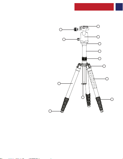
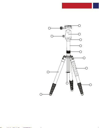
Appearance & Interface Description
1. Mounting Plate
2. Mounting Screw
3. Vertical Tilt Lock Knob
4. Pivot Head
5. Pivot Head Adjustment Column
6. Rapid Adjustment Center Column
7. Center Column Locking
8. Flip Leg Locks
9. Telescopic Legs
10. Monopod Convertible Leg
11. Gravity Hook
12. Secure Leg Locks
13. Rubber Feet
3
2
3
8
7
6
5
4
1
9
10
13
12
11
English
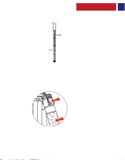
1. Adjusting the Height Of The Center Column:
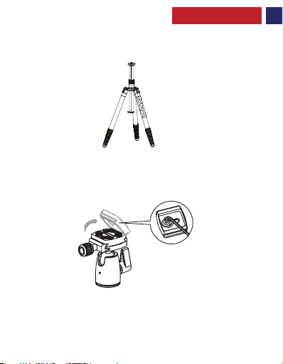
2. Installation and Removal Of Mounting Plate
Usage Instructions
• Loosen the Center Column Locking.
• Elevate the center column to the desired height.
• Tighten the Center Column Locking Knob.
• Loosen the Locking Knob for Mounting Plate
• Flip up the Mounting Plate to release it.
4

English
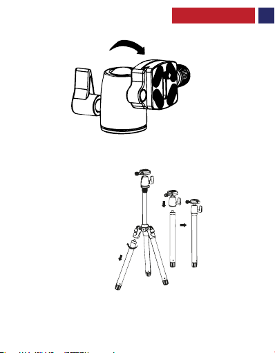
• The mounting plate can be tilted for portrait shots.
• Detach one of the tripod legs as shown.
• Detach the pivot head from the tripod.
• Screw the pivot head onto the detached tripod leg.
3. Adjusting the Tilt of the Mounting Plate
4. Monopod Functionality
5
English
• Press the Flip Leg Lock to release the leg lock mechanism.
• Tilt to desired angle
• Press again to lock the legs in place.
5. Extending the Tripod Legs:
6. Tripod Leg Angle Adjustment
• Grasp the monopod’s rubber foot and twist it counter clockwise to loosen.
• Extend the monopod leg sections to the desired height.
• Twist the foot clockwise to lock the legs.
6
Descripción del Aspecto y la Interfaz
1. Placa de montaje
2. Tornillo de montaje
3. Perilla de bloqueo de la inclinación vertical
4. Cabeza giratoria
5. Columna de ajuste de la cabeza giratoria
6. Columna central de ajuste rápido
7. Bloqueo de la columna central
8. Bloqueos de pata de volteo
9.Patas telescópicas
10.Pata convertible del monopie
11.Gancho por gravedad
12.Bloqueos de pata segura
13.Pies de goma
2
3
8
7
6
5
4
1
9
10
13
12
11
7
Spanish

8
Spanish
1. Cómo ajustar la altura de la columna central:
2. Instalación y Retirada de la Placa de Montaje
Instrucciones de Uso
• Afloje el bloqueo de la columna central.
• Eleve la columna central a la altura deseada.
• Apriete la perilla de bloqueo de la columna central.
• Afloje la perilla de bloqueo de la placa de montaje
• Gire la placa de montaje hacia arriba para liberarla.
Spanish
• Separe una de las patas del trípode como se muestra.
• Separe la cabeza giratoria del trípode.
• Atornille la cabeza giratoria en la pata separada del trípode.
• La placa de soporte se puede inclinar para fotos de retrato.
3. Como ajustar la inclinación de la placa de montaje
4. Funcionalidad del monopie
9
Table of contents
Languages:
Other Promate Camera Accessories manuals


Popular Camera Accessories manuals by other brands

Viltrox
Viltrox EF-NEX Mount instructions

Calumet
Calumet 7100 Series CK7114 operating instructions

Ropox
Ropox 4Single Series User manual and installation instructions

Cambo
Cambo Wide DS Digital Series Main operating instructions

Samsung
Samsung SHG-120 Specification sheet

Ryobi
Ryobi BPL-1820 Owner's operating manual


