4
1. Safety
1.1 Safety Instructions
For safety reasons, installers are responsible for familiarizing themselves
with the contents of this document and all warnings before performing any
installation and service.
1.1.1 Battery Handling Guide
• Do not expose the battery to an open ame.
• Do not place the product near to highly ammable materials.
• Do not expose or place near water sources such as downspouts or sprinklers.
• Do not store or install the product in direct sunlight.
• Do not install the product in an airtight enclosure or in an area without
ventilation.
• Do not install the product in living area of dwelling units or in sleeping
units Other than within storage and utility spaces.
• Store in a cool and dry place. (Do not store in greenhouses or storage areas
for hay, straw, cha, animal feed, fertilizer, vegetables, or fruit products.)
• Store the product on a at, level surface.
• Store the product out of reach of children and animals.
• Store the product in clean environment, free of dust, dirt and debris.
• Do not allow unqualied personnel to disconnect, disassemble or repair the
product. Product handing, service and installation must be carried out by
qualied and competent personnel.
• Do not damage the Product by dropping, deforming, impacting, cutting or
penetrating with a sharp object. Doing so may cause a re or leakage of
electrolytes.
• Do not touch the product if liquid spills on it. There is a risk of electric
shock. Handle the battery wearing insulated gloves.
• Do not step on the product or the product՚s packaging since the product may
be damaged.
• Do not place any foreign objects on top of the Battery Pack and on the
cooling n.
• Do not put the battery pack upside down on the ground.
• Do not connect the power cables at terminal the block in the opposite
direction.
• Do not charge or discharge a damaged battery.
• If the Product is installed in a garage or carport, ensure there is adequate
clearance from vehicles.
• The battery pack has been certied IP55 and can be installed indoors as well
as outdoors. However, if installed outdoors, do not allow the battery pack to
be exposed to direct sunlight or water sources, as they may cause:
- Power limitation phenomena in the battery (with a resulting decrease in energy
production by the system).
-
Premature wear of the electrical/electromechanical and mechanical components.
- Reduction in performance, performance warranty and possible damage of the
battery
• Only use the product with a LGES-authorized inverter.
For a list of compatible inverters, go to :
https://www.lgessbattery.com/us (in case of North America)
https://www.lgessbattery.com/au (in case of Australia)
https://www.lgessbattery.com/eu (in case of all EU-countries in general)
https://www.lgessbattery.com/de (in case of Germany)
https://www.lgessbattery.com/it (in case of Italy)
https://www.lgessbattery.com/es (in case of Spain)
• Do not connect any AC conductors or photovoltaic conductors directly to
the battery pack. These are only to be connected to the inverter.
2. Installation
RESU FLEX can be installed in a Standing or Wall-mounting form.
2.1 Installation location
Make sure that the installation location meets the following conditions:
• The building is designed to withstand earthquakes.
• The location is far away from the sea, to avoid salt water and humidity.
• The oor is at and level.
• There are no ammable or explosive materials nearby.
• The optimal ambient temperature is between 20 and 30°C.
• The temperature and humidity stays at a constant level.
• There is minimal dust and dirt in the area.
• There are no corrosive gases present, including ammonia and acid vapor.
The Resu Battery pack is rated at IP55 and thus can be installed outdoors as well
as indoors. However. if installed outdoors, do not allow the battery pack to be
exposed to direct sunligh and moisture.
NOTE
If the ambient temperature is outside the operating temperature range (-10℃ ~
50℃), the battery pack will stop operation to protect itself. The optimal ambient
temperature range for the battery pack is between 20℃ and 30℃.
Frequent exposure to harsh temperatures may deteriorate the performance and
life of the battery pack.
NOTE
2.2 Standing Installation
2.2.1 Clearance
At least
300mm
At least
500mm
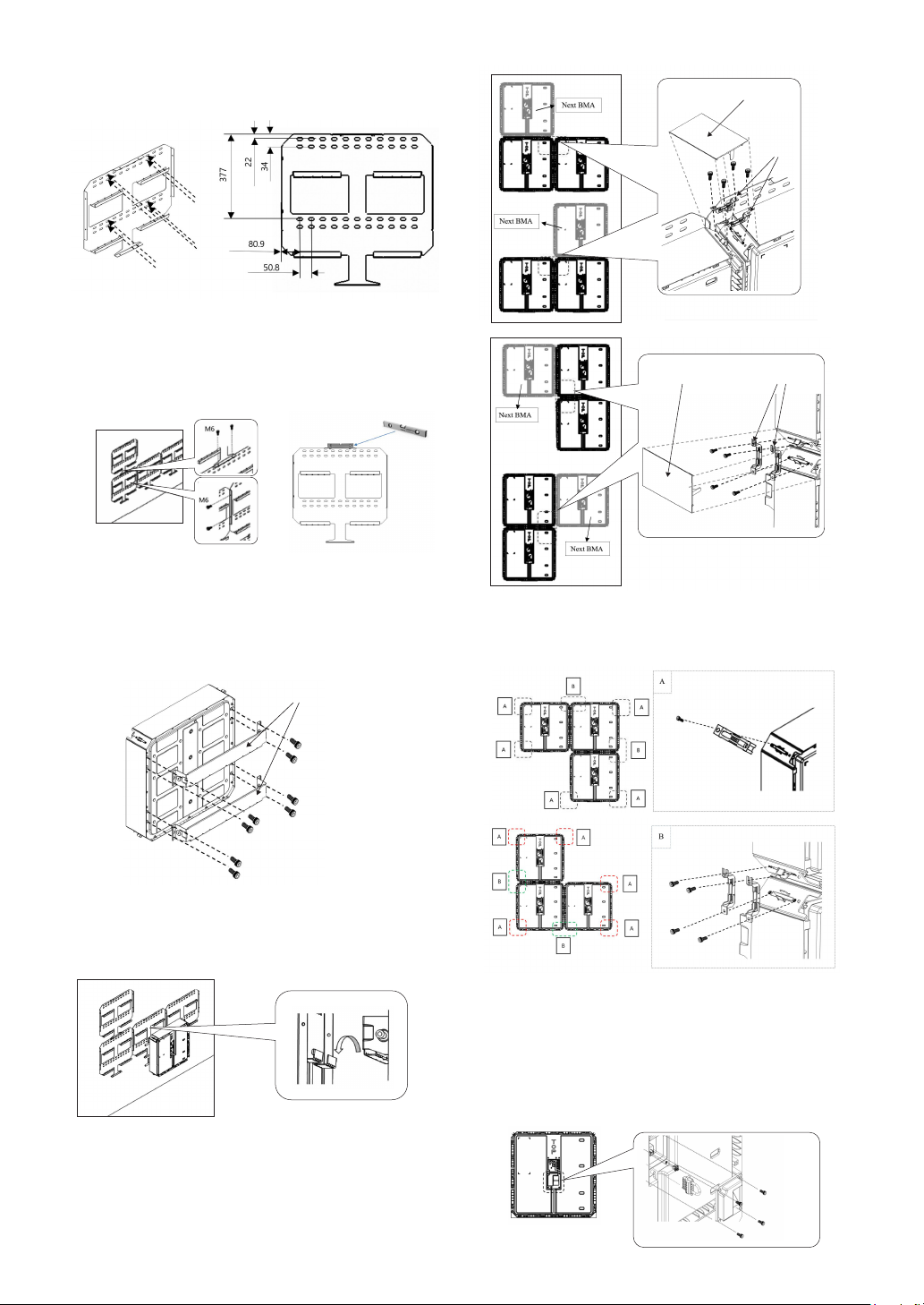
2.2.2 Installation and Cable Connection of BMA and
BPU for stand type
1. Assemble the Basic Standing Bracket to the BMA.
M6 Bolt
M6 bolt (a torque of 5N·m)
Basic standing bracket
Basic