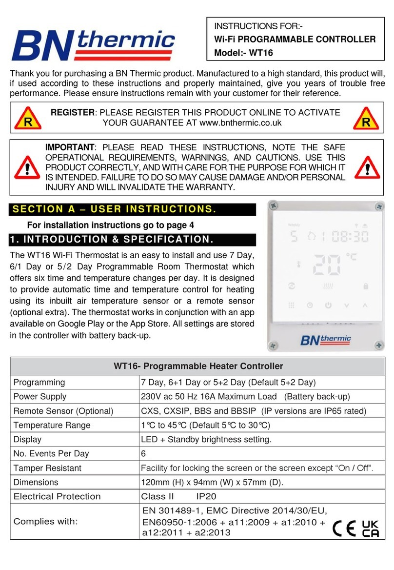
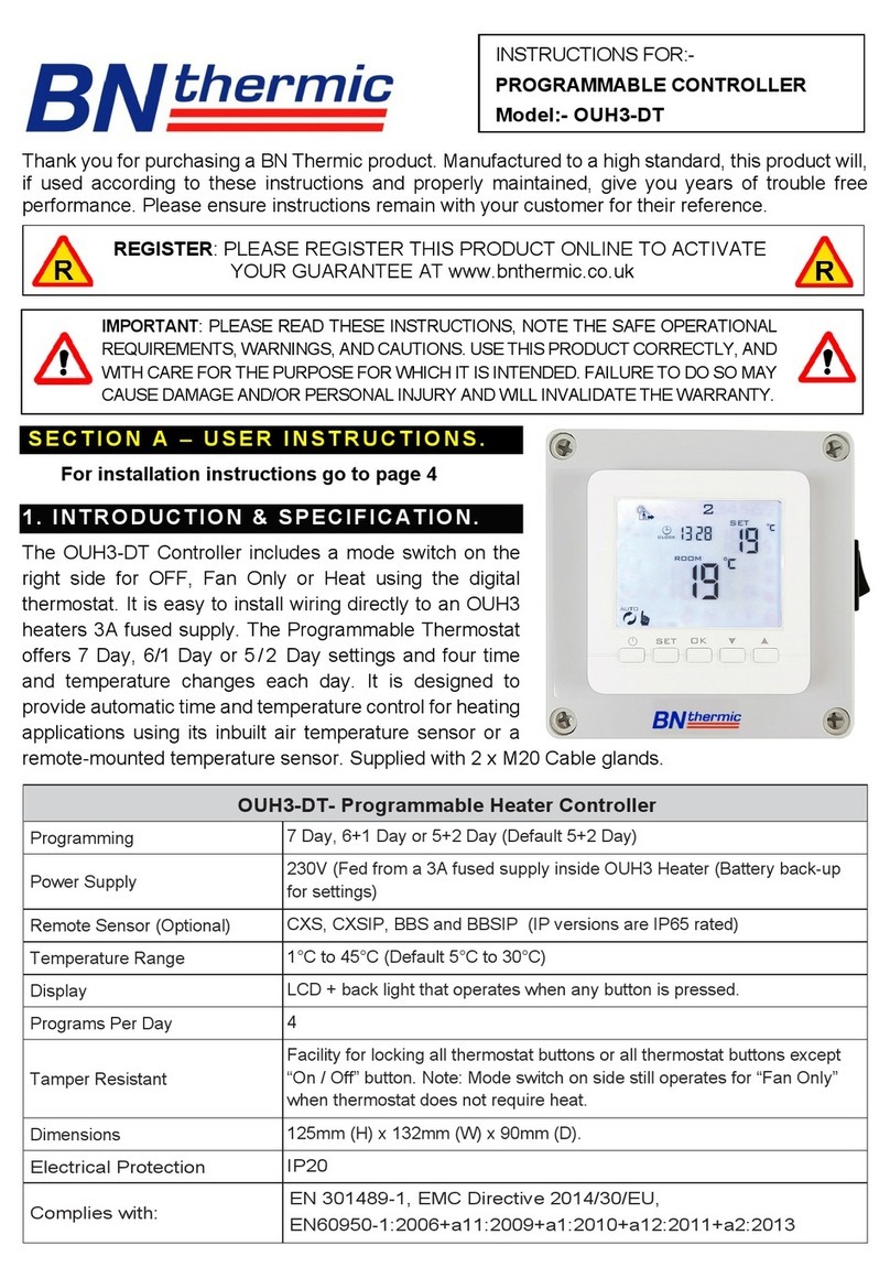
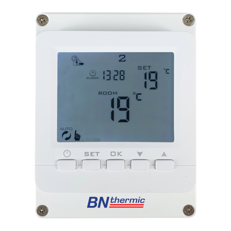
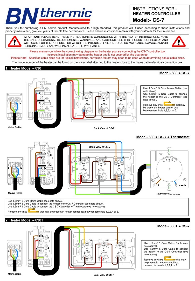
BN Thermic SystemX CX6 User manual

Thank you for purchasing a BN Thermic product. Manufactured to a high standard, this product will, if used
according to these instructions and properly maintained, give you years of trouble free performance. Please
ensure instructions remain with your customer for their reference.
SECTION A –USER INSTRUCTIONS.
For installation instructions go to page 7
1. INTRODUCTION & SPECIFICATION.
The CX6 Thermostat is an easy to
install and use 7 Day, or 5/2 Day
Programmable Room Thermostat
which offers two, four or six time and
temperature changes each day, with
different programmes available for
weekdays and for weekends. It is
designed to provide automatic time
and temperature control of SystemX
heating systems. A backlit LCD screen
and easy to use function buttons
ensures simplified programming and
operation for all users.
The Thermostat includes special
features designed to save you
energy. All settings are stored in the
controller with battery back-up. If you
wish to place the thermostat in a
different location from the heaters an
optional remote sensor can be added
to the controller.
IMPORTANT: PLEASE READ THESE INSTRUCTIONS, NOTE THE SAFE OPERATIONAL
REQUIREMENTS, WARNINGS, AND CAUTIONS. USE THIS PRODUCT CORRECTLY,
AND WITH CARE FOR THE PURPOSE FOR WHICH IT IS INTENDED. FAILURE TO DOSO
MAY CAUSE DAMAGE AND/OR PERSONAL INJURY AND WILL INVALIDATE THE
WARRANTY.
PROGRAMMABLE HEATER CONTROLLER
REGISTER: PLEASE REGISTER THIS PRODUCT ONLINE TO ACTIVATE
YOUR GUARANTEE AT www.bnthermic.co.uk
CXS –RemoteSensor
(OptionalExtra)

Specification
CX6- Programmable Heater Controller
Programming
7 Day or 5/2 Day
Power Supply
Powered from any SystemX heater through network cable
(battery back-up)
Temperature Sensor Type
±1°C at 20°C
Temperature Adjustment Range
5°C to 30°C
Plastic
Thermoplastic, flame retardant
Number of Programs Per Day
2, 4 or 6 (Default: 2)
Factory Pre-Set Programs per Day
2, 4 or 6 (Default: 2)
BST/GMT Time Change
Automatic
Tamper Resistant
Various screen / button locks if required to stop misuse
Remote Temperature Sensor
Available as optional extra (Part No CXS)
Dimensions
120mm (L) x 80mm (W) x 35mm (D)
Protection Rating
IP30
Complies with:
EN60730-1 EN 60730-2.7, EMC Directive 2014/30/EU,
LVD Directive 2014/35/EU
Special Features
1) Adaptive Start
The Adaptive Start function adjusts the starting time for the heating according to the temperature measured
within the room / building. Instead of setting an arbitrary time for the heating to come on, you programme the
time that the room / building should be at the desired temperature. Up to 10% of energy costs can be saved,
as the warm up time is automatically reduced according to the ambient temperature. Many users set their
heating to start a couple of hours before use to warm up the room / building. With the Adaptive Start function
you don’t need to do this. The actual start time is automatically delayed or advanced to ensure your room /
building reaches the set temperature by the programmed time. The Adaptive Start function is designed to work
with well insulated rooms / buildings that do not have a throughput of people and doors or windows being
opened regularly before the heating period.
2) Logical Heat Controller
Only works when Full Power in Settings is set to “YES”. Reduces the overrun of temperature by turning down
the power on each heater as it gets close to the temperature set point. You should not notice the effect on the
temperature but you should see a slight reduction in your energy bill.
3) Various screen locks
To stop the problem with passers by pressing buttons and adjusting the thermostat there are various ways of
locking the screen and disabling the buttons from working.
2

2 . QUICK OPERATING GUIDE.
❶Main Display :–Back lit when you touch any button displays actual temperature, set temperature, time, day of
week,program numberand mode of operation.
❷Modebutton :–Used toselect mode of operation (Auto /Fan only / Off / Program).
❸─ button :–Used to decrease a settable value e.g. when in “Auto” mode decreases the set point temperature until
next program.
❹+ button :–Used to increase a settable value e.g. when in “Auto” mode increases the set point temperature until
next program.
❺Enter button:–Generally usedtostoreinformation inprogrammingmode.
❻Actualtemperature.
❼Time of day 12 hour format (a = am p = pm ).
❽Set pointtemperature.
❾Modeof operation ( Auto , FanOnly, Off or Program).
❿Dayoftheweek.
⓫Shows “Heat” when set point below actual temperatureandheatersare ON.
⓬Shows which program number you are on for the today (P1, P2, P3 etc) or the program number from yesterday if the
controller has not reached the change over time for today’s first program (YP2, YP4 or YP6 equal yesterday’s P2,
P4orP6)
3
❶
❷
❸
❹
❺
❿
❾
⓬
⓫
❽
❼
❻

3. FACTORY PRE-SET PROGRAMMES.
This Programmable Controller has been designed to be a simple to use thermostat, requiring minimal user
intervention with a pre-programmed heating profile. By default, the controller is set to 2 programs per day if
you wish to change this to 4 or 6 programs (see section 19 / 21 Page 10).
Pre-Set Time / Temperatures
2Programs per Day
4Programsper Day
6Programs per Day
P1
8am
20˚C
8am
20˚C
7am
20˚C
P2
6pm
5˚C
12pm
15˚C
9am
15˚C
P3
-
-
2pm
20˚C
12pm
20˚C
P4
-
-
6pm
5˚C
2pm
15˚C
P5
-
-
-
-
4pm
20˚C
P6
-
-
-
-
10pm
5˚C
NOTE:- The same times and temperatures are set for each day of the week if you don’t require heating for one day
for example a Sunday this needs to be changed by entering the programming mode and either setting the time and /
or temperature to stop the controller from turning the heaters on. e.g. if you are on 2 programs a day and you don’t
require any heat on a Sunday just go into Sunday’s setting and change the temperature for P1 from 20˚C down to
5˚C (see section 5 page 5 for more information).
4. SELECTING THE DIFFERENT MODES.
If none of the thermostat button locks are in operation by pressing the MODE button you can toggle through
the following different operating modes.
1.AUTO –This is the normal mode where the thermostat will turn the heaters on and off according to the
programs that have been set. If you need to adjust these programs see section 5.
2.FAN –Generally used in the summer to move air around by turning all the fans on in all the heaters. The
fans will stay on 24/7 if not turned off before leaving the building. Turning off is done by pressing the
MODE button until OFF is displayed.
3. OFF –All heaters are turned off and will remain off until mode is changed.
4.PROG –Used to enter the time and temperature programming.
4

5. CHANGING THE PROGRAM SETTINGS.
If you wish to change the number of programs per day go to “Master Settings” section 19 page 10 and adjust
the number of programs per day before continuing.
Using the MODE button toggle the display to PROG and then follow the instructions below to set.
If you don’t press any button for 2 mins the display will exit the settings mode.
5

6. TEMPORARY ADJUSTING TEMPERATURE SET POINT IN AUTO MODE.
The set point can be temporarily adjusted in auto mode by pressing the +or –buttons. This is only allowed if
the screen is not locked. NOTE:-This will only adjust the set point until the next programme.
7. PERMANENT LOCKING TEMPERATURE SET POINT IN AUTO MODE.
The Set Point can be changed and locked in Auto mode if required.
1. First adjust the Set Point to desired temperature by pressing the +or –buttons.
2. Then to Lock the "Set Point" press the -button and the ENTER button simultaneously and hold for 3
seconds until the "Auto" on the display changes to "Lock".
3. Unlocking is the reversal of the above.
NOTE:- The display will still operate BUT all 4 buttons will be disabled (except the unlock combination!) and
the temperature set point will not change. When you unlock the controller will resume in Auto Mode. This
feature is useful if you wish to set the thermostat to a frost stat mode to protect a building when not in general
use.
8. LOCKING THE CONTROLLER OFF.
The Controller can be locked in the OFF position disabling it from working.
1. To lock the controller "OFF" press the -button and the MODE button simultaneously and hold for 3
seconds until the display changes to "Lock" and "OFF" appears where set temperature is normally
displayed.
2. Unlocking is the reversal of the above.
NOTE:- When you unlock the controller it will revert back to AUTO Mode and either turn the heaters on if
below temperature set point or they will remain off if above.
9. LOCKING THE CONTROLLER.
The controller can only be locked in its standard modes (AUTO, FAN or OFF).
1. First select the mode you wish to lock the controller in.
2. Now lock the display pressing the +button and the ENTER button simultaneously and hold for 3
seconds until the three ӿappear on the display.
3. Unlocking is the reversal of the above.
NOTE:- The display and programs will still operate BUT all 4 buttons will be disabled (except the unlock
combination!).
10. FROST PROTECTION.
The thermostat can be used to protect areas from dropping below certain temperatures (normally 5°C for frost
protection)
If required simply follow section 7 above but set the temperature to 5°C before locking the thermostat.
6

7
SECTION B –INSTALLATION AND MASTER SETTINGS.
11. INSTALLATION SAFETY INSTRUCTIONS.
11.1 ELECTRICAL SAFETY
WARNING! Under No circumstances may you take a 230V supply to this controller. The controller works on
low voltage (less than 30V) and to ensure the system is safe 230V supplies MUST be kept away from this
controller.
WARNING! It is the responsibility of the owner and the operator to read, understand and comply with the
following:
You must also read and understand the following instructions concerning electrical safety.
The Health & Safety at Work Act 1974 makes owners of electrical appliances responsible for the safe
condition of those appliances and the safety of the appliance operators. If in any doubt about electrical safety,
contact a qualified electrician.
Installation should always be carried out by a qualified electrician or a competent person in accordance with
current electrical regulation.
11.2 GENERAL SAFETY INSTRUCTIONS
Remove all packaging and store it away from children, check the package for visible damage or tampering.
Only use recommended attachments and parts. To use unauthorised parts may be dangerous and will
invalidate your warranty.
DO NOT use in areas where hazardous gases or dusts may be present.
DO NOT disassemble the controller for any reason. The circuit board has no user serviceable parts.
DO NOT use this controller to perform a task for which it has not been designed.
Please leave the user instructions with the end user where they should be kept in a safe
place for further reference.
12. INSTALLATION.
CHOOSING A LOCATION FOR YOUR CX6
The CX6 controller should be mounted on an internal wall approximately 1.5 meters from floor level and
should be in a position away from draughts, direct heat and sunlight.
Ensure that there will be enough space on the left hand side of the controller to allow free air movement
though the controller so it can detect the room temperature. If you wish to place the controller in a separate
area such as an adjacent room or cupboard, a remote sensor will be required to detect the temperature.
Remote sensor part number- CXS.

13. MOUNTING THE CONTROLLER.
To remove the back plate from the front of the controller
gently push the bottom of the back plate whilst gently
prising the front panel away. The bottom of the controller
must be released from the back plate first before gently
unclipping the top.
Screw to the wall ensuring the “UP arrows” are pointing
the correct way and the green terminal block is at the top.
The CX6 can also be mounted on a single gang flush
wiring box using the 2 x semi-circular slotted holes in the
back. DO NOT overtighten the fixing screws as you will
deform the box and the connection block in the back will
not engage with the circuit board correctly.
14. ELECTRICAL CONNECTIONS.
A network cable is used to connect the controller to any
of the SystemX heaters (read notes below regarding
cables)
•We recommend you use our network cables as they
have been thoroughly tested with all heaters and
controllers and are 100% totally compatible.
•Problems arising from using non-standard or inferior
network cables are not covered by the guarantee.
•Network cables with “wings” on the boot connections
will not fit into the controller socket.
Bring sufficient length of network cable through one of
the knock outs in the back plate to allow a lazy loop to be formed before plugging into the back of the circuit
board. If you are not fitting additional sensors or linking the controller to a building management system (BMS)
leave the links in the back plate in position.
To refit the front panel to the back
Locate the 2 holes on the top of the front cover onto the two lugs on the top of the back box. Now gently click
the bottom of the front cover onto the back box. No force should be applied if the front cover does not fit easily
the network cable is possibly caught please check before trying again.
If you are not fitting an additional sensor or switches go to section 18.
15. USING A REMOTE SENSOR (CXS) WITH THE CONTROLLER.
1) Remove the existing link betweenP1and P2.
2) DO NOTremovethelink betweenT1andT2.
3) Usinganyinsulatedcopper wireconnecttheremotesensortoterminals P2 andP3.
8
Network Cable
Socket
8

16. USING WITH AN EXTERNAL SWITCH OR KEY SWITCH.
You can disable or enable the
controllerfrom working by removingthe
link between T1 andT2and connecting
the two terminals to a zero volt switch.
AT NO TIME MUST A VOLTAGE BE
SENTDOWNTHESEWIRES.
With the link removed or broken the
controller turns OFF all the heaters and
locks the buttons on the front from
working. When re-made controllergoes
into AUTOMode and turns heaters ON
if required.
17. USING WITH A BMS SYSTEM.
You can alsoconnect the controller to a
building management system (BMS).
This is done by removing the link
between T1 and T2 and connecting the
two terminals to a zero volt relay of
whichthecoiliscontrolledbytheBMS.
AT NO TIME MUST A VOLTAGE BE
SENT DOWN THESE WIRES FROM
THEBMS.
18.CONNECTING THE CONTROL CIRCUIT OF SYSTEM X HEATERS TOGETHER
Network socketsonthe heatersare bi-directional. This means that eithersocketmay beused forin or out.
1) Connectthe CX6 controllerintoanyheatersnetworksocket.
2) Daisychain allheaterstogether usingnetwork cables.
9

19. CHANGING THE MASTER / DEFAULT SETTINGS.
There are various master / default settings that can be changed by entering the default settings.
To enter these settings, press the MODE button and the ENTER button simultaneously and hold for 3
seconds. You are now in settings mode shown in diagram to the right if you don’t press any button for 2
minutes display reverts back to AUTO mode. If you wish to exit the settings screen press MODE button and
the ENTER button simultaneously.
20. SETTING THE TIME AND DATE.
The time and date are factory set so it will not normally be necessary to do this on site.
If you need to change the time after entering the settings screen (shown above) press the MODE button until
the display shows Settings - Time and the Hour is flashing.
Now using +and –buttons adjust to correct hour (24h format) and then press ENTER button and minutes will
start to flash. Now using +and –buttons adjust to correct minutes and then press ENTER button.
If you need to change the date after entering the settings screen (shown above) press the MODE button until
the display shows Settings - Date and the Month is flashing.
Now using +and –buttons adjust to correct month and then press ENTER button and day will start to flash.
Now using +and –buttons adjust to correct day and then press ENTER button and year will start to flash. Now
using +and –buttons adjust to correct year and then press ENTER button.
Note:- If you forget to press the ENTER button new setting will not be stored
21. OTHER SETTINGS.
S.Time –(Auto) Automatic adjustment of British Summer Time can be turned on or off here.
Temp Offset –(0⁰C) Used if you wish to fine turn or calibrate the thermostat, can adjust the temperature up or
down by 1,2,3,4 or 5⁰C.
Full Power –(Yes) Setting NO reduces all the heaters maximum output by between 1/3 and 1/2 their output.
Setting YES returns the heaters to their maximum output. INSTALLER PLEASE NOTE - Adequate size cables
MUST still be used to take maximum load. Do not use this as a way of reducing cable sizes.
Progs / Day –(2) Set the number of programs per day you require either 2, 4 or 6.
Fan Mode –(Off) Setting OFF means that the fan turns on and off when the heat turns on and off. Setting ON
means that the Fan remains on continuously in AUTO mode regardless of the heat turning on and off This is
general only used on air curtain heaters.
Adapt Start –(Off) Turns on or off adaptive start see page 2 for full description on how it works.
Reset to New –(NO) Rests the controller to its “NEW” factory settings. Select YES and press Enter to reset.
Warning: resetting to new changes all user inputs and master settings back to factory settings which are
shown in green above. Only the current time and date settings are not affected.
10

11

22. FAULT FINDING.
Thermostat screen is blank.
The controller receives its power through the network cable linking the thermostat to the heater. Check that
this cable is connected and that there is power to at least one of the heaters in the system. Most of the
problems that occur are due to installers manufacturing their own network cables and either getting two
wires crossed or not quite crimping all 8 pins of the network plug correctly. For this reason, we strongly
recommend you use our or another manufactures network cables that are pre-made and already tested.
First two heaters work then last three heaters don’t.
Check there is power going to all the heaters that don’t work and if so, change the network cable that goes
between the last working heater and the first heater that does not work. This usually only happens if
network cables are self manufactured.
Can I use straight or cross over network cables?
Either or both can be used on the system and they will not affect the working of the heaters.
All the heaters were working now one has stopped.
Check the mains wiring to the heater affected the controller is not capable of turning off just one heater.
Buttons don’t work on the controller.
The controller is designed with various button locks to stop miss use of the controller. Please look at the
screen of the controller and follow the corresponding instructions below to unlock.
To Unlock the controller, press the -button
and the MODE button simultaneously and
hold for 3 seconds until the display changes.
To Unlock the controller, press the -button
and the ENTER button simultaneously and
hold for 3 seconds until the display changes.
To Unlock the controller, press the +button
and the ENTER button simultaneously and
hold for 3 seconds until the display
changes.
This lock is applied by an external switch
and cannot be undone by pressing any
combination of buttons. (see section 16 & 17
for more information).
NOTE: It is our policy to continually improve products and as such we reserve the right to alter data, specifications and
component parts without prior notice.
REGISTER:
Activate your warranty by registering online at www.bnthermic.co.uk
and retain this installation data for future reference.
IMPORTANT: No liability is accepted for incorrect use of this product.
WARRANTY: Your BN Thermic product is guaranteed for one year from date of
purchase. We will repair or replace at our discretion any part found to be defective.
We cannot assume any consequential liability. This guarantee in no way prejudices
your rights under common law and is offered as an addition to consumer liability
rights. CX6INS-v01-1
Thisproduct conformstoEUDirective2002/96/EC.
This appliance bears the symbol of the crossed waste bin. This indicates that, at the end of its useful life, it must not be
disposed of as domestic waste, butmust be taken to a collection centre forwaste electricaland electronic equipment. It is the
user's responsibility to dispose of this appliance through the appropriate channels. Failure to do so may incur penalties
establishedbylawsgoverningwaste disposal.
BNThermic Ltd,
34StephensonWay,
Crawley,RH101TN
Tel:+44 (0)1293547361
Email:sales@bnthermic.co.uk
Web:www.bnthermic.co.uk
Table of contents
Other BN Thermic Controllers manuals

BN Thermic
BN Thermic RT26 User manual

BN Thermic
BN Thermic OUH3-WiFi User manual

BN Thermic
BN Thermic WD16 User manual

BN Thermic
BN Thermic W16C User manual

BN Thermic
BN Thermic WT26 User manual

BN Thermic
BN Thermic RD16 User manual

BN Thermic
BN Thermic WT16 User manual

BN Thermic
BN Thermic CS-7 User manual

BN Thermic
BN Thermic RT16 User manual

BN Thermic
BN Thermic B16C User manual