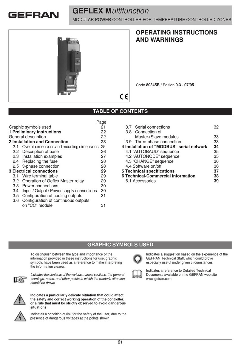
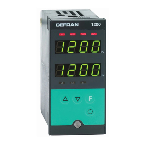
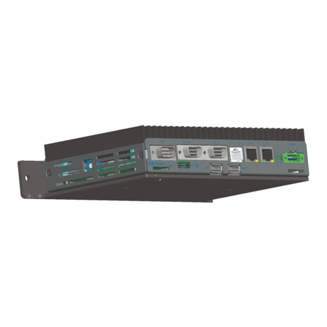
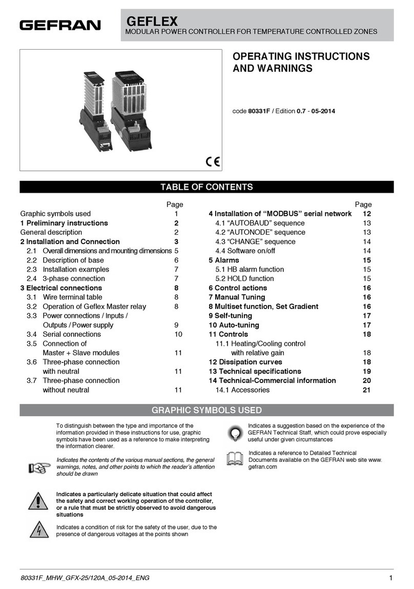
manuals.online logo
Brands
  1. Home
  2. •
  3. Brands
  4. •
  5. gefran
  6. •
  7. Controllers
  8. •
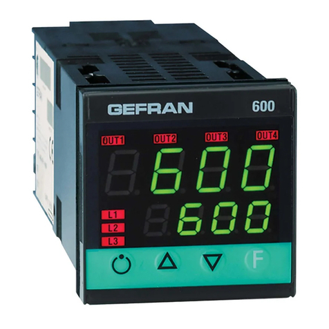
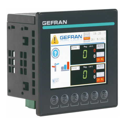
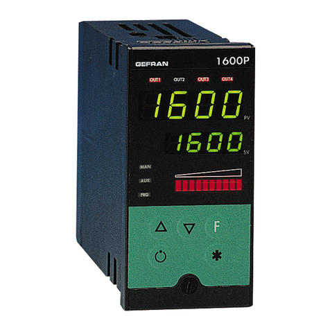
  9. gefran 600 User manual

gefran 600 User manual

Cencal Out 4Modbus
• Serial line / output 4
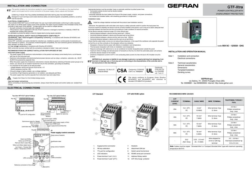
Advice for Correct Installation for EMC
Instrument power supply
• The power supply to the electronic equipment on the
switchboards must always come directly from an isolation
devicewithafusefortheinstrumentpart.
• The electronic instruments and electromechanical power
devicessuchasrelays,contactors,solenoidvalves,etc.,must
alwaysbepoweredbyseparatelines.
• When the electronic instrument power supply is strongly
disturbed by the commutation of transistor or power units
or motors, an isolation transformer should be used for the
controllersonly,earthingthescreen.
• Itisessentialthattheplanthasagoodearthconnection:
 -thevoltagebetweenneutralandearthmustnotbe>1V
 -theOhmicresistancemustbe<6W;
• Ifthemainsvoltagefluctuatesstrongly,useavoltagestabilizer.
• In the proximity of high frequency generators or arc welders,
useadequatemainsfilters.
• The power supply lines must be separate from the instrument
inputandoutputones.
Inputs and outputs connection
• Theexternallyconnectedcircuitsmustbedoublyisolated.
• To connect the analogue inputs (TC, RTD) the following is
necessary:
 -physicallyseparatetheinputcablesfromthoseofthepower
 supply,theoutputsandthepowerconnections.
 -usewovenandscreenedcables,withthescreenearthedin
 onepointonly
• To connect the regulating and alarm outputs (contactors,
solenoid valves, motors, fans, etc.), fit RC groups (resistance
andcondensersinseries)inparalleltotheinductiveloadsthat
operateinAlternatingCurrent.
 (Note: all the condensers must conform to VDE (class X2)
standards and withstand a voltage of at least 220V AC. The
resistancesmustbeatleast2W).
• Fit a 1N4007 diode in parallel with the coil of this can be
removedinductiveloadsthatoperateinDirectCurrent.
GEFRAN S.p.A. declines all responsibility for any
damage to persons or property caused by tampering,
neglect, improper use or any use which does not
conform to the characteristics of the controller and to
the indica tions given in these Instructions for Use.
Warnings and instructions for mounting to the panel
Instructions for installation category II, pollution
level 2, double isolation.
• onlyfor lowpower supply:supply fromClass 2or lowvoltage
limitedenergysource.
• the power supply lines must be separate from the controller
inputandoutputones
• grouptheinstrumentstogetherkeepingthemseparatefromthe
poweredpartoftherelay
• do not install high-power remote switches, contactors, relays,
thyristor power units (especially the “phase angle” type),
motors,etc.inthesameswitchboard
• avoiddust,humidity,corrosivegassesandheatsources
• do not block the ventilation holes: the working temperature
mustbebetween0...50°C
• surroundingair:50°C
• use60/75°Ccopper(Cu)conductoronly,wiresizerange2xNo
22-14AWG,Solid/Stranded
• useterminaltighteningtorque0.5Nm
Nominal ambient conditions
Before supplying the Controller with power, make
sure that the mains voltage is the same as that
shown in the last number of the order code.
600
ouT1 ouT2 ouT3
SV
ouT4
L1
L2
L3
F
8888
8888
This section contains the instructions necessary for correct
installation of the 600 controllers into the machine control
panel or the host system and for correct connection of the
controller power supply, inputs, outputs and interfaces.
Before proceeding with installation read the following
warnings carefully!
Remember that lack of observation of these warnings
could lead to problems of electrical safety and
electromagnetic compatibility, as well as invalidating
the warranty.
Electrical power supply
• the controller is NOT equipped with an On/Off switch: the user
mustprovideatwo-phasedisconnecting switch thatconformsto
the required safety standard (CE marking), to cut off the power
supplyupstreamofthecontroller.
 The switch must be located in the immediate vicinity of the
controller and must be within easy reach of the operator. One
switchmaycontrolmorethanonecontroller.
• ifthecontrollerisconnectedtoNOTisolatedelectricalequipment
(e.g.thermocouples),theearthconnectionmustbemadewitha
specific conductor to prevent the connection itself from coming
directlythroughthemachinestructure.
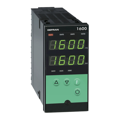
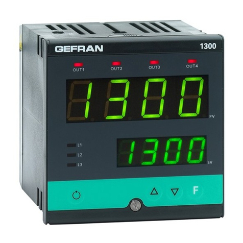
600
CONTROLLER
INSTALLATION AND OPERATION MANUAL
Side1 1Dimensionsandcut-out;panelmounting
 2Installationandconnection
 3Descriptionoffaceplate
 4Connections
Side2 5Technicalspecifications
 6“Easy”programmingandconfiguration
 7Quickstartguide
The complete manual is available for download from the
website www.gefran.com
GEFRANspareservestherighttomakeanyaestheticor
functionalchangeatanytimeandwithoutnotice.
cod.80311 - 11/2012 - ENG
1 • DIMENSIONS AND CUT-OUT;
PANEL MOUNTING
99
10
45
45
48
70
70
63
48
Forcorrectandsafeinstallation,
followtheinstructionsand
observethewarningscontained
inthismanual.
Panel mounting:
Tofixtheunit,insertthebracketsprovidedintotheseatsoneither
sideofthecase.
Tomounttwoormoreunitssidebyside,respectthecut-out
dimensionsshowninthedrawing.
2 • INSTALLATION AND CONNECTION
3 • DESCRIPTION OF FACEPLATE
Automatic/ManualadjustmentselectionActiveonlywhenPV
displayvisualisestheprocessvariable
Function indicators
Indicatesmodesofoperation
MAN/AUTO= OFF(automaticcontrol)
 ON(manualcontrol)
SETPONT1/2= OFF(IN1=OFF-localSetpoint1)
 ON(IN1=ON-localSetpoint2)
SELFTUNING=ON(enabledSelf)
 OFF(disabledSelf)
“Inc” and “Dec” key
Presstoincrement(decrement)anynumericalparameter••Increment(decrement)speedisproportionaltotimekeystays
pressed••Theoperationisnotcyclic:oncethemaximum(minimum)valueofafieldisreached,thevaluewillnotchangeevenif
thekeyremainspressed.
PV Display:Indicationofprocessvariable
ErrorIndication:LO,HI,Sbr,Err
LO=thevalueofprocessvariableis<diLO_S
HI=thevalueofprocessvariableis>diHI_S
Sbr=faultysensororinputvalueshigherthanmax.limits
Err=PT100thirdwireopenedforPT100,PTCorinput
valueslowerthanmin.limits(i.e.:TCwrongconnection)
Function key
Givesaccesstothevariousconfigurationphases••
Confirmschangeofsetparametersandbrowsesnextor
previousparameter(ifAuto/Mankeyispressed)
SV display:Indicationofsetpoint
Indication of output states
OUT1(AL1);OUT2(Main);OUT3(HB);OUT4(HB)
5Aat
250Vac/30Vdc
relay
Standard:
100...240Vac±10%
Optional:
11...27Vac/dc±10%
Max.power10VA;50/60Hz
4 • CONNECTIONS
• Ammeter outputs/input
6
5
4
3
2
1
7
8
9
10
11
12
18
17
16
15
14
13
19
20
21
22
23
24
19
21
20
22
-
+
Out2
Out1
• Power Supply
23
24
~
~
TOP
6
5
-
+
Out3(Al2)
Ing.T.A.
PWR
Standard
configuration
4...20mA
Connectat20mAinput
Usewiresof
adequatediameter
(min.1mm2)
PT100,JPT100,
PTC,NTC
• Pt100 / PTC / NTC
• Device structure • Identification of boards
3
1
2
Pt1003wires
PTC/NTC
/Pt1002wires
Availablethermocouples:
J,K,R,S,T
(B,E,N,L,U,G,D,Ccustomlinearization
isavailable)
-Observepolarities
-Forextensions,usethecorrect
 compensatingcableforthetypeofTCused +
-
• TC Input
2
1
4
2
3
1
+ 24Vo15V
VT
-
+
+
S
-
Ri=50Ω
4
2
3
1
+24Vo15V
VT
-
+
+

-
Ri=50Ω
T
T
• Linear input with 3-wire transmitter
• Inputs
• Input 1 linear with transmitter 2 wires
9
10
11
+
-
TX
A
(Data+)
RX
-
+
12
9
10
11
12
DISPLAY
POWER
SERIALINTERFACE/OUT4
Selectsignalat
contact3
CPUboard-Componentside
CPU
PT100
+VT
Linearinput
indccurrent
20mA,
Ri=50Ω
Linearinputin
dcvoltage
60mV,1VRi>1MΩ
5V,10VRi>10KΩ
2
1+
-
• Linear input (I)
4
1
2
-
+
• Linear input (V)
RS485isolatedserialline
SeeserialcarddatasheetforCencalconfiguration
-5Aat250Vac/30Vdcrelay
-24V,10Vat20mAlogic
-triac20...240Vac,1A±10%
-Digitalinsulated24Vac/dc
-5A/250Vacrelayonly
-5Aat250Vac/30vdcrelay
-24V,10Vat20mAlogic
-continuous0…10V,0/4…20mA
-analog0…10V,0/4…20mAfor
 transmission,resolution12bit
-inputfromcurrenttransformer
 50mAac,10Ω50/60Hz
-logicinput24V,5mAorfrom
 no-voltagecontact
-Digitalinsulated24Vac/dc
Userconfigurablegenericoutput
11
B
(Data-)
24V
15V
10V
5V
1,23V
R20
S2
NB.:youcankeeptheOUT1relayenergizedatpower-upby
insertingjumperS2andremovingresistanceR20.
IN/OUTboards
(seeappendix)
Powerboard-Solderside
Selecttransmitter
voltage
Altitude Upto2000m
Working/storage
temperature 0..50°C/-20...70°C
Noncondensing
relativehumidity 20...85%
GEFRAN spaviaSebina,74-25050Provagliod’Iseo(BS)
Tel.03098881-fax0309839063Internet:http://www.gefran.com
PV
• if the controller is used in applications with risk of damage to
persons,machineryormaterials,itisessentialtoconnectitup
toauxiliary alarmequipment. Itis advisableto makesure that
alarmsignalsarealsotriggeredduringnormaloperation.
 ThecontrollermustNOTbeinstalledinflammableorexplosive
environments; it may be connected to equipment operating
in such atmospheres only by means of appropriate and
adequatetypesofinterface,conformingtotheapplicablesafety
standards.
Notes Concerning Electrical Safety and
Electromagnetic Compatibility:
CE MARKING:
The instrument conforms to the European Directives 2004/108/
CEand2006/95/CEwithreferencetothegenericstandards:
EN 61000-6-2(immunityinindustrialenvironment)EN 61000-6-3
(emissioninresidentialenvironment)EN 61010-1(safety).
Series 600 temperature controllers are mainly designed to
operateinindustrial environments, installedonthe switchboards
orcontrolpanelsofproductiveprocessmachinesorplants.
ThissectioncontainsalistoftheTechnicalSpecificationsforthe600Controller.
5 • TECHNICAL SPECIFICATIONS
7• QUICK START GUIDE
6 • “EASY” PROGRAMMING and CONFIGURATION
al.1
P.V. / S.V.
P.V./S.V.
Processvariable(PVdisplay)
WorkSetpoint(SVdisplay)or
controloutputvaluewithcontroller
inmanual
Alarmpoint1(scalepoints)
LEVEL 1 MENU
• CFG
• InP
h.pb
h.it
h.dt
h.p.x
Xy.i
Proportionalband
forheatingor
hysteresis
inregulationON/OFF
Integraltime
forheating
Derivativetime
forheating
Maximumpowerlimit
forheating
0...999.9%
fullscale
0.00...99.99
min
0.00...99.99
min
0.0...100.0%
Alarm1hysteresis ±999
scalepoints
typ. Probetype,signal,enablecustomlinearization,andmain
inputscale(See type table, page 6)
dp.s
lo.s
Decimalpointposition
formaininputscale
Minimumlimitofmain
inputscale
Maximumlimitofmain
inputscale
dP_S Format
 0 xxxx
 1 xxx.x
 2 xx.xx
 3 x.xxx
min...maxinputrange
selectedintyP
min...maxinputrange
selectedintyP
xi.s
xi.l
lo.l Lowerlimitforlocal
setpointandabsolute
alarms
Lo.S...Hi.S
Upperlimitforlocal
setpointandabsolute
alarms
Lo.S...Hi.S
Alarm
type1
AL.x.t Direct(highlimit) Absolute Normale
  Inverse(lowlimit) orrelative Symmetrical
   toactivesetpoint (window)
 0 direct absolute normal
 1 inverse absolute normal
 2 direct relative normal
 3 inverse relative normal
 4 direct absolute symmetrical
 5 inverse absolute symmetrical
 6 direct relative symmetrical
 7 inverse relative symmetrical
AL.1.t, AL.2.t, AL.3.t
a1.t
(t.2 Cycletimefor
Out2
(HeatorCool)
1...200sec.
Pro Protectioncode
Prot Display Modification
 0 SP,alarms SP,alarms
 1 SP,alarms SP
 2 SP
+4 todisableInP,Out
+8 todisableCFG
+128enablesfullconfiguration
THEEASYCONFIGURATIONISSUITABLEFORVERSIONS
WITHTWOOUTPUTS(OUT1,OUT2).TOACCESSTHEOTHER
PARAMETERS,ADD128TOTHEProVALUE.
+8todisableatpower-onuntilfirstalarm
+16toenablealarmmemory
+32Hysbecomesdelaytimewhenalarmtrips(0...999sec.)
 (excludingsymmetricalabsolute)
+64Hysbecomesdelaytimewhenalarmtrips(0...999min.)
 (excludingsymmetricalabsolute)
InP
Out
PAS=99
Pro
Inputsettings
Outputsettings
PAS
Custommenu
Password
Protectioncode
CFG
S4Jumper
(CPU)
ON
0...999sec.
If+32inA1.t
0...999min.
If+64inA1.t
Withthetimescales
0-999sec/0-999minthedecimal
pointhasnomeaning
(fordP.Sdifferentfrom0”)
• Out • Prot
123
FIRST STEPS DESCRIPTION 1.INPUT CONNECTION
·Openthepackage
·Powerupthedeviceaccording
 tothe“Supply”informationon
 thelabel.
Output
states
Changeparametervalue
Scanmenu/
parameters
Sbr- Err
forsensornot
connectedor
inshort
~
600
ouT1 ouT2 ouT3
PV
SV
ouT4
L1
L2
L3
F
8888
8888
400
TC
+
-
2
1
Pt100
3
1
2
Pt1003
wires
PTC/NTC/
Pt1002wires
T
T
Ifthecorrectvalueoftheinput
(forexample,temperature)
isnotdisplayed,checkthe
connections.
600
ouT1 ouT2 ouT3
PV
SV
ouT4
L1
L2
L3
F
8888
8888
400
600
ouT1 ouT2 ouT3
PV
SV
ouT4
L1
L2
L3
F
8888
8888
Input programming
-tyP parameter
-OnInpmenu
Input sensor
Sensor
type
Sensor
type
0 TCJ°C 30 PT100°C
1 TCJ°F 31 PT100°F
2 TCK°C 32 JPT100°C
3 TCK°F 33 JPT100°F
4 TCR°C 34 PTC°C
5 TCR°F 35 PTC°F
6 TCS°C 36 NTC°C
7 TCS°F 37 NTC°F
8TCT°C 44 4...20mA
9TCT°F 46 0...10V
23
~
24
Electrical
energy
CONNECTING OUTPUTS ACCORDING TO ORDER CODE
4
600-R-D-X-X-X
19
-
+20
19
-
+20
21
22
19
20
Alarm
21
22
Alarm
21
22
Alarm
21
22
600-R-R-X-X-X
Alarm
600-R-D-R-X-X 600-R-R-R-X-X
19
20
HeatingHeatingHeatingHeating Solidstate
powerunit
Solidstate
powerunit
5 6 1.CHECKING OUTPUT OPERATION
H: LEDOUT2 ON
AL1:LEDOUT1 OFF
C: LEDOUT3 OFF
H: LEDOUT2 OFF
AL1: LEDOUT1 ON
C: LEDOUT3 ON
PROGRAMMING SP
Usethe and buttonstosetthe
controlreferencevalue(SV)onthemain
page.(seepoint2DESCRIPTION)
PROGRAMMING AL1
Press Fonceonthemainpage:you
willseeAL.1,whichletsyouchangethe
referencevalueofAlarm1.
600
ouT1 ouT2 ouT3
PV
SV
ouT4
L1
L2
L3
F
8888
8888
400
600
ouT1 ouT2 ouT3
PV
SV
ouT4
L1
L2
L3
F
8888
8888
400
600
ouT1 ouT2 ouT3
PV
SV
ouT4
L1
L2
L3
F
8888
8888
600
ouT1 ouT2 ouT3
PV
SV
ouT4
L1
L2
L3
F
8888
8888
35 15
25 25
SetSP=AL1= PV+10,
wait20seconds,andcheckthe
stateoftheLEDs.
SetSP=AL1= PV-10,
wait20seconds,andcheckthe
stateoftheLEDs.
Cooling
5
6ToenabletheCoolingoutputit
isnecessarytosetthefollowing
parameters
[tr= 8 (krd menu)
rl.3 =1 (0vt menu) Cooling
5
6ToenabletheCoolingoutputit
isnecessarytosetthefollowing
parameters
[tr= 8 (krd menu)
rl.3 =1 (0vt menu)
Display 2x4digits,green,height10and7mm
Keys 4mechanicalkeys(Man/Auto,INC,DEC,F)
Accuracy 0.2%f.s.±1at25°Croomtemperature
Thermaldrift 0.005%f.s./°C
Maininput(configurabledigitalfilter) TC,RTD,PTC,NTC60mV,1VRi≥1MW;5V,10VRi≥10KW;20mARi=50W
Samplingtime120msec.
TypeTC(Thermocouples)(ITS90) J,K,R,S,T(IEC584-1,CEIEN60584-1,60584-2)
acustomlinearizationcanbeinserted
Coldjunctionerror 0.1°/°C
RTDType(temperatureresistance)(ITS90) Pt100(DIN43760),JPT100
Max.lineresistanceforRTD 20W
PTCType/NTCType 990W,25°C/1KW,25°C
Safety detectionofshortcircuitoropeningofprobes,LBAalarm,HBalarm
°C/°Fselection configurablefromfaceplate
Linearscaleranges -1999...9999,withconfigurabledecimalpointposition
Controls Pid,Autotune,on-off
pb-dt-it 0.0...999.9%-0.00...99.99min-0.00...99.99min
Action heat/cool
Controloutputs on/off,continuous
Max.powerlimitheat/cool 0.0...100.0%
Cycletime 0...200sec
Mainoutputtype relay,logic,continuous(0...10V/4...20mA)
Softstart 0.0...500.0min
Faultpowersetting -100.0...100.0%
Automaticblanking maintainsPVvaluedisplay,optionalexclusion
Configurablealarms upto3alarmfunctionsassignabletoanoutputandconfigurableof
type:maximum,minimum,symmetrical,absolute/relative,LBA,HB
Alarmmasking exclusionduringwarmup,memory,resetfromfaceplateand/orcontact
Typeofrelaycontact NO(NC),5A,250V/30Vdccosj=1
Logicoutputforstaticrelays 24V±10%(10Vminat20mA)
Triacoutput 20...240Vac±10%,1Amax,inductiveandresistiveloadI2t=128A
Isolateddigitaloutput OpticallyisolatedMOSoutput,1500Vrms,equivalenttoanNOcontrol,max
40VAC/DCImax100mA,ResistanceONmax0.8W
Transmitterpowersupply 24Vdc,max30mAshort-circuitprotection
Analogueretransmission 10V/20mARloadmax500W12bitresolution
Digitalinputs Ri=4,7KW(24V,5mA)orfromterminalnotsuppliedwithpower
Serialinterface(optional) RS485,isolated
Baudrate 1200,2400,4800,9600,19200
Protocol GefranCENCAL/MODBUS
Amperometricinputoption C.T.50mAac,50/60Hz,Ri=10W
Powersupply(switchingtype) (standard)100...240Vac/dc±10%Vac50/60Hz
(optional)11...27Vac/dc±10%10VAmax
Faceplateprotection IP65
Working/Storagetemperaturerange 0...50°C/-20...70°C
Relativehumidity 20...85%Urnon-condensing
Environmentalworkingconditions forindooruse,altitudesupto2000m
Installation panel,removablefaceplate
Installationspecifications installationcategoryII,pollutionlevel2,doubleisolation
Weight 160g(completeversion)

Other manuals for 600

3

Other gefran Controllers manuals

gefran GPC Owner's manual

gefran

gefran GPC Owner's manual

gefran 600 User manual

gefran

gefran 600 User manual

gefran 650 Series Quick guide

gefran

gefran 650 Series Quick guide

gefran GF LOOPER User manual

gefran

gefran GF LOOPER User manual

gefran ADV20 series Operator's manual

gefran

gefran ADV20 series Operator's manual

gefran GSLM User manual

gefran

gefran GSLM User manual

gefran SIEIDrive ADV200 User manual

gefran

gefran SIEIDrive ADV200 User manual

gefran GFW Series User manual

gefran

gefran GFW Series User manual

gefran GFW 40-300A User manual

gefran

gefran GFW 40-300A User manual

gefran 400 User manual

gefran

gefran 400 User manual

gefran GEFLEX-ETHERNET User manual

gefran

gefran GEFLEX-ETHERNET User manual

gefran AGy -L User manual

gefran

gefran AGy -L User manual

gefran 1600 User manual

gefran

gefran 1600 User manual

gefran SIEIDrive ADV50 Series Operator's manual

gefran

gefran SIEIDrive ADV50 Series Operator's manual

gefran 40T 72 PID User manual

gefran

gefran 40T 72 PID User manual

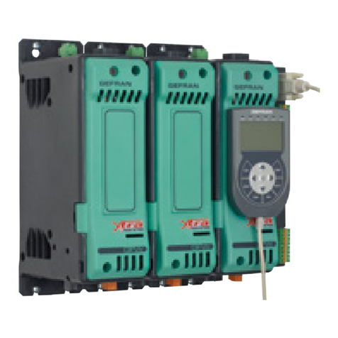
gefran GTF-Xtra Guide

gefran

gefran GTF-Xtra Guide

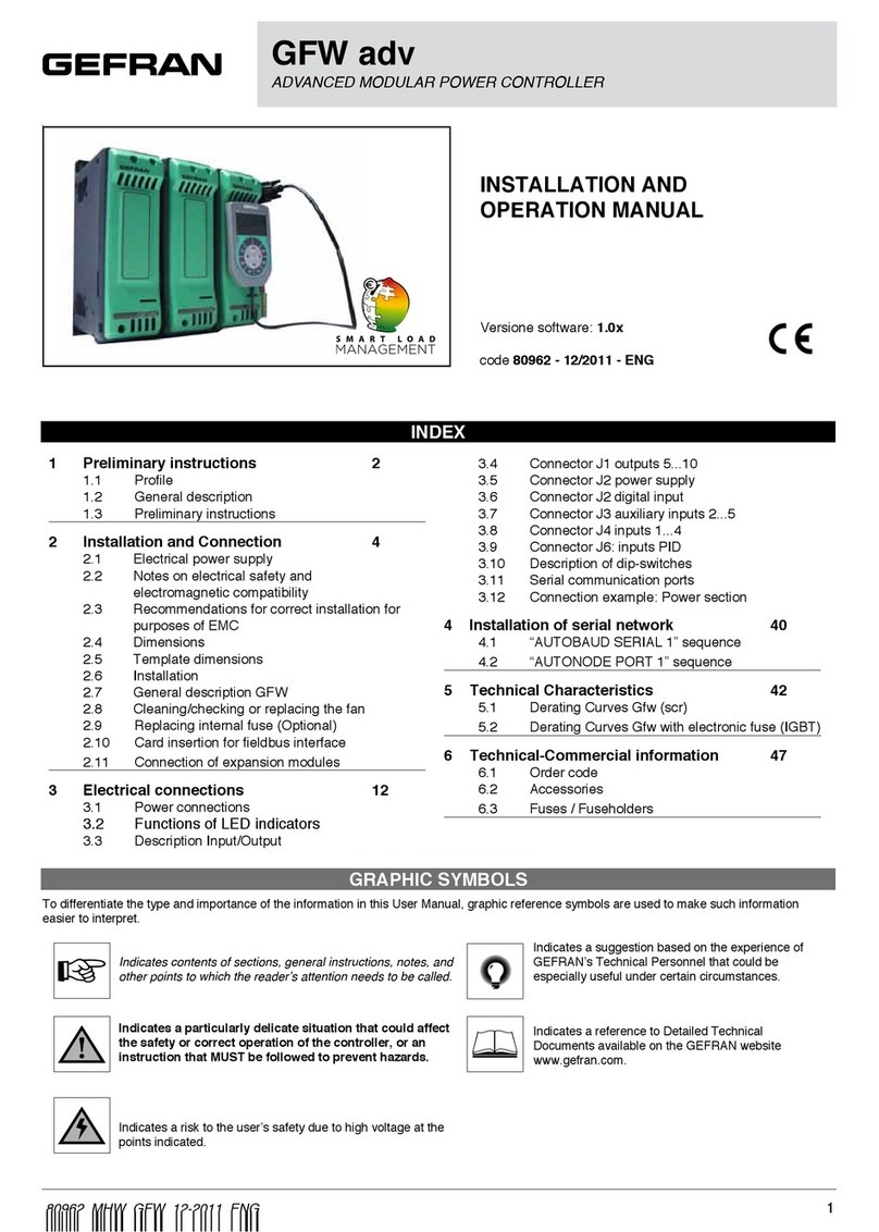
gefran GFW ADV Owner's manual

gefran

gefran GFW ADV Owner's manual

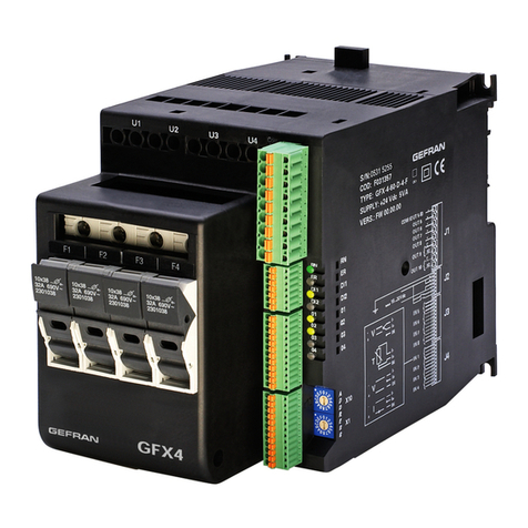
gefran GFX4 User manual

gefran

gefran GFX4 User manual

gefran AGL50-EV Series User manual

gefran

gefran AGL50-EV Series User manual

gefran GPC 40-600A Technical specifications

gefran

gefran GPC 40-600A Technical specifications

gefran WATTCOR W312 User manual

gefran

gefran WATTCOR W312 User manual

gefran IR-12 Owner's manual

gefran

gefran IR-12 Owner's manual

gefran 450-R-R-1 User manual

gefran

gefran 450-R-R-1 User manual

gefran ADV200 Series User manual

gefran

gefran ADV200 Series User manual

Popular Controllers manuals by other brands

SODECA EC CONTROL user manual

SODECA

SODECA EC CONTROL user manual

EOS EmoStyle Di Installation and operation manual

EOS

EOS EmoStyle Di Installation and operation manual

TAC Forta M800 manual

TAC

TAC Forta M800 manual

Theben HMG 8 operating instructions

Theben

Theben HMG 8 operating instructions

TRIATEK FMS-1655L installation manual

TRIATEK

TRIATEK FMS-1655L installation manual

LOVATO ELECTRIC RGK600 instruction manual

LOVATO ELECTRIC

LOVATO ELECTRIC RGK600 instruction manual

Rockwell Automation Allen-Bradley GuardLogix 5570 installation instructions

Rockwell Automation

Rockwell Automation Allen-Bradley GuardLogix 5570 installation instructions

Light Rider LR512 Technical data sheet

Light Rider

Light Rider LR512 Technical data sheet

VADA Rain2Main quick start guide

VADA

VADA Rain2Main quick start guide

elco PISCES MINIFILL E1/1 INSTRUCTIONS FOR INSTALLATION, SERVICING & MAINTENANCE

elco

elco PISCES MINIFILL E1/1 INSTRUCTIONS FOR INSTALLATION, SERVICING & MAINTENANCE

iNels IART2-1 instruction manual

iNels

iNels IART2-1 instruction manual

Keba KeDrive D3-DA BG3 Operation manual

Keba

Keba KeDrive D3-DA BG3 Operation manual

Mitsubishi Electric MELSEC iQ-F FX5 user manual

Mitsubishi Electric

Mitsubishi Electric MELSEC iQ-F FX5 user manual

Mec MEGR-6120 Series instruction manual

Mec

Mec MEGR-6120 Series instruction manual

Oakton TEMP 9000 user manual

Oakton

Oakton TEMP 9000 user manual

GeoVision GV-AS210 user manual

GeoVision

GeoVision GV-AS210 user manual

Novanta ScanMaster user manual

Novanta

Novanta ScanMaster user manual

Stamford AS440 Specification, Installation and Adjustments

Stamford

Stamford AS440 Specification, Installation and Adjustments

manuals.online logo
manuals.online logoBrands
  • About & Mission
  • Contact us
  • Privacy Policy
  • Terms and Conditions

Copyright 2025 Manuals.Online. All Rights Reserved.