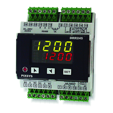
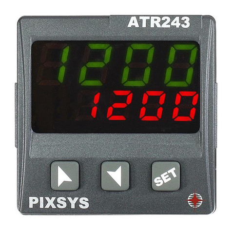
Pixsys ATR224 User manual

ATR224-DRR224
Controller / Regolatore / Régulateur
User manual / Manuale d’uso / Manuel utilisateur


Table of contents
1 Safety guidelines.......................................................................................................................................................... 6
1.1 Organization of safety notices.................................................................................................................. 6
1.2 Safety Precautions ....................................................................................................................................... 6
1.3 Precautions for safe use.............................................................................................................................. 7
1.4 Environmental policy / WEEE .................................................................................................................... 7
2 Model Identification.................................................................................................................................................... 8
3 Technical Data.............................................................................................................................................................. 8
3.1 General Features .......................................................................................................................................... 8
3.2 Hardware Features ...................................................................................................................................... 8
3.3 Software Features ........................................................................................................................................ 8
3.4 Programming mode.................................................................................................................................... 8
4 Dimensions and Installation..................................................................................................................................... 9
5 Electrical wirings .......................................................................................................................................................... 9
5.1 Wiring diagram........................................................................................................................................... 10
5.1.a Power Supply.................................................................................................................................... 10
5.1.b Analogue Input AI1......................................................................................................................... 10
5.1.c Digital input ..................................................................................................................................... 12
5.1.d Digital output................................................................................................................................... 12
5.1.e Relay output Q1 - Q2 (for ATR224-12ABC) ................................................................................. 12
5.1.f Relay output Q1 - Q2 (for DRR224-12ABC) ................................................................................ 12
6 Display and Key Functions....................................................................................................................................... 13
6.1 Meaning of Status Lights (Led)................................................................................................................ 13
6.2 Keys................................................................................................................................................................ 13
7 Controller Functions.................................................................................................................................................. 13
7.1 Modification of main and alarm setpoint value ................................................................................ 13
7.2 Automatic Tune .......................................................................................................................................... 14
7.3 Manual Tune................................................................................................................................................ 14
7.4 Tuning once ................................................................................................................................................. 14
7.5 Digital input functions.............................................................................................................................. 14
7.6 Automatic / Manual regulation for % output control....................................................................... 15
7.7 LATCH ON Function ................................................................................................................................... 15
7.8 Soft-Start Function..................................................................................................................................... 16
8 Reading and configuration through NFC ............................................................................................................ 16
8.1 Configuration through memory card ................................................................................................... 17
8.2 Memory card creation/update................................................................................................................ 17
8.3 Configuration loading from memory card.......................................................................................... 17
9 Loading default values............................................................................................................................................. 17
10 Access configuration ................................................................................................................................................. 18
10.1 Parameters list functioning ..................................................................................................................... 18
11 Table of configuration parameters........................................................................................................................ 19
12 Alarm Intervention Modes.......................................................................................................................................30
12.a Absolute or threshold alarm active over (par. 123
A L .1 . F .
=
A b . u P. A .
)...........................................................30
12.b Absolute or threshold alarm active below (par. 123
A L .1 . F .
=
A b . u P. A .
)........................................................30
12.c Absolute or threshold alarm referred to command setpoint active over (par. 123
A L .1 . F .
=
Ab . c. u.A.
) 30
12.d Absolute or threshold alarm referred to command setpoint active below (par. 123
A L .1 . F .
=
Ab . c.L.A.
)30
12.e Band alarm (par. 123
A L .1 . F .
=
band
).................................................................................................................. 31
12.f Asymmetric band alarm (par. 123
A L .1 . F .
=
A.band
)........................................................................................ 31
12.g Upper deviation alarm (par. 123
A L .1 . F .
=
up.dev.
).......................................................................................... 31
12.h Lower deviation alarm (par. 123
A L .1 . F .
=
Lo.dev.
)..........................................................................................32
12.1 Alarms label................................................................................................................................................. 32
13 Table of Anomaly Signals.........................................................................................................................................32
Indice degli argomenti
1 Norme di sicurezza ....................................................................................................................................................36

1.1 Organizzazione delle note di sicurezza ................................................................................................36
1.2 Note di sicurezza.........................................................................................................................................36
1.3 Precauzioni per l’uso sicuro ..................................................................................................................... 37
1.4 Tutela ambientale e smaltimento dei rifiuti / Direttiva WEEE ......................................................... 37
2 Identificazione di modello .......................................................................................................................................38
3 Dati tecnici...................................................................................................................................................................38
3.1 Caratteristiche generali ............................................................................................................................38
3.2 Caratteristiche Hardware.........................................................................................................................38
3.3 Caratteristiche software ...........................................................................................................................38
3.4 Modalità di programmazione ................................................................................................................39
4 Dimensioni e installazione ......................................................................................................................................39
5 Collegamenti elettrici................................................................................................................................................40
5.1 Schema di collegamento..........................................................................................................................40
5.1.a Alimentazione..................................................................................................................................40
5.1.b Ingresso analogico AI1................................................................................................................... 41
5.1.c Ingressi digitali................................................................................................................................. 42
5.1.d Uscita digitale ..................................................................................................................................42
5.1.e Uscita relè Q1 - Q2 (per ATR224-12ABC).....................................................................................42
5.1.f Uscita relè Q1 - Q2 (per DRR224-12ABC).................................................................................... 42
6 Funzione dei visualizzatori e tasti.......................................................................................................................... 43
6.1 Significato delle spie di stato (Led)......................................................................................................... 43
6.2 Tasti................................................................................................................................................................43
7 Funzioni del regolatore.............................................................................................................................................43
7.1 Modifica valore setpoint principale e di allarme................................................................................ 43
7.2 Tuning automatico ....................................................................................................................................44
7.3 Tuning manuale .........................................................................................................................................44
7.4 Tuning once .................................................................................................................................................44
7.5 Funzioni da Ingresso digitale ..................................................................................................................44
7.6 Regolazione automatico / manuale del controllo % uscita ............................................................45
7.7 Funzione LATCH ON...................................................................................................................................45
7.8 Funzione Soft-Start....................................................................................................................................46
8 Lettura e configurazione via NFC...........................................................................................................................46
8.1 Configurazione tramite memory card .................................................................................................. 47
8.2 Creazione / aggiornamento della memory card................................................................................ 47
8.3 Caricamento configurazione da memory card .................................................................................. 47
9 Caricamento valori di default................................................................................................................................. 47
10 Accesso alla configurazione....................................................................................................................................48
10.1 Funzionamento della lista parametri....................................................................................................48
11 Tabella parametri di configurazione.....................................................................................................................49
12 Modi d’intervento allarme.......................................................................................................................................60
12.a Allarme assoluto o allarme di soglia attivo sopra (par. 123
A L .1 . F .
=
A b . u P. A .
)..........................................60
12.b Allarme assoluto o allarme di soglia attivo sotto (par. 123
A L .1 . F .
=
A b . u P. A .
)...........................................60
12.c Allarme assoluto o allarme di soglia riferito al setpoint di comando attivo sopra (par. 123
A L .1 . F .
=
Ab . c. u.A.
)..................................................................................................................................................................60
12.d Allarme assoluto o allarme di soglia riferito al setpoint di comando attivo sotto (par. 123
A L .1 . F .
=
Ab . c.L.A.
)....................................................................................................................................................................60
12.e Allarme di Banda (par. 123
A L .1 . F .
=
band
)........................................................................................................ 61
12.f Allarme di banda asimmetrica (par. 123
A L .1 . F .
=
A.band
)............................................................................ 61
12.g Allarme di deviazione superiore (par. 123
A L .1 . F .
=
up.dev.
)......................................................................... 61
12.h Allarme di deviazione inferiore (par. 123
A L .1 . F .
=
Lo.dev.
)...........................................................................62
12.1 Label allarmi................................................................................................................................................62
13 Tabella segnalazioni anomalie..............................................................................................................................62
Index des sujets
1 Consignes de sécurité................................................................................................................................................66
1.1 Organisation des avis de sécurité...........................................................................................................66

1.2 Avis de sécurité............................................................................................................................................66
1.3 Précautions pour l’usage en toute sécurité ..........................................................................................67
1.4 Politique environnementale / DEEE .......................................................................................................67
2 Identification du modèle..........................................................................................................................................68
3 Données techniques..................................................................................................................................................68
3.1 Caractéristiques générales.......................................................................................................................68
3.2 Caractéristiques Hardware ......................................................................................................................68
3.3 Caractéristiques Software........................................................................................................................68
3.4 Mode de programmation ........................................................................................................................ 69
4 Dimensions et Installation.......................................................................................................................................69
5 Raccordements électriques ..................................................................................................................................... 69
5.1 Plan des connexions ..................................................................................................................................70
5.1.a Alimentation .................................................................................................................................... 70
5.1.b Entrée analogique AI1.................................................................................................................... 70
5.1.c Entrées digitale ................................................................................................................................ 71
5.1.d Sorties digitales ...............................................................................................................................72
5.1.e Sortie relai Q1 - Q2 (pour ATR224-12ABC) .................................................................................72
5.1.f Sortie relai Q1 - Q2 (pour DRR224-12ABC) ................................................................................72

6 - ATR224 - DRR224 - User manual
Introduction
The controllers ATR224 and DRR224 stands out for the bright display which ensures optimal visibility
and increased level of information for the operator beside a scrolling Help function.
These controllers relies on Pixsys flagship programming mode by NFC/RFID technology with dedicated
App MyPixsys for Android devices (same already used for Pixsys signal converters and STR indicators)
not requiring wirings and power supply, allowing quick set-up/updates on site.
The outputs can be selected as command/multiple alarm modes. Serial communication standard is
RS485 with Modbus RTU/Slave protocol. Useful power supply with extended range 24 to 230VAC /
VDC with galvanic insulation of the net.
1 Safety guidelines
Read carefully the safety guidelines and programming instructions contained in this manual before
connecting/using the device.
Disconnect power supply before proceeding to hardware settings or electrical wirings to avoid risk of
electric shock, fire, malfunction.
Do not install/operate the device in environments with flammable/explosive gases.
This device has been designed and conceived for industrial environments and applications that rely
on proper safety conditions in accordance with national and international regulations on labour
and personal safety. Any application that might lead to serious physical dama ge/ life risk or involve
medical life support devices should be avoided.
Device is not conceived for applications related to nuclear power plants, weapon systems, flight
control, mass transportation systems.
Only qualified personnel should be allowed to use device and/or service it and only in accordance to
technical data listed in this manual.
Do not dismantle/modify/repair any internal component.
Device must be installed and can operate only within the allowed environmental conditions.
Overheating may lead to risk of fire and can shorten the lifecycle of electronic components.
1.1 Organization of safety notices
Safety notices in this manual are organized as follows:
Safety notice Description
Danger! Disregarding these safety guidelines and notices can be life-threatening.
Warning! Disregarding these safety guidelines and notices can result in severe injury or
substantial damage to property.
Information! This information is important for preventing errors.
1.2 Safety Precautions
This product is UL listed as open type process control equipment. Danger!
If the output relays are used past their life expectancy, contact fusing or burning may
occasionally occur.
Always consider the application conditions and use the output relays within their
rated load and electrical life expectancy. The life expectancy of output relays varies
considerably with the output load and switching conditions.
Danger!
Loose screws may occasionally result in fire.
For screw terminals of relays and of power supply, tighten screws to tightening torque
of 0,51 Nm. For other terminals, tightening torque is 0,19 Nm
Warning!
A malfunction in the Digital Controller may occasionally make control operations
impossible or prevent alarm outputs, resulting in property damage. To maintain safety
in the event of malfunction of the Digital Controller, take appropriate safety measures,
such as installing a monitoring device on a separate line.
Warning!
Table of contents

User manual - ATR224 - DRR224 - 7
1.3 Precautions for safe use
Be sure to observe the following precautions to prevent operation failure, malfunction, or adverse
affects on the performance and functions of the product. №t doing so may occasionally result in
unexpected events. Do not handle the Digital Controller in ways that exceed the ratings.
• The product is designed for indoor use only. Do not use or store the product outdoors or in any of
the following places.
- Places directly subject to heat radiated from heating equipment.
- Places subject to splashing liquid or oil atmosphere.
- Places subject to direct sunlight.
- Places subject to dust or corrosive gas (in particular, sulfide gas and ammonia gas).
- Places subject to intense temperature change.
- Places subject to icing and condensation.
- Places subject to vibration and large shocks.
• Installing two or more controllers in close proximity might lead to increased internal temperature
and this might shorten the life cycle of electronic components. It is strongly recommended to
install cooling fans or other air-conditioning devices inside the control cabinet.
• Always check the terminal names and polarity and be sure to wire properly. Do not wire the
terminals that are not used.
• To avoid inductive noise, keep the controller wiring away from power cables that carry high voltages
or large currents. Also, do not wire power lines together with or parallel to Digital Controller
wiring. Using shielded cables and using separate conduits or ducts is recommended. Attach a
surge suppressor or noise filter to peripheral devices that generate noise (in particular motors,
transformers, solenoids, magnetic coils or other equipment that have an inductance component).
When a noise filter is used at the power supply, first check the voltage or current, and attach the
noise filter as close as possible to the Digital Controller. Allow as much space as possible between
the Digital Controller and devices that generate powerful high frequencies (high-frequency
welders, high-frequency sewing machines, etc.) or surge.
• A switch or circuit breaker must be provided close to device. The switch or circuit breaker must be
within easy reach of the operator, and must be marked as a disconnecting means for the controller.
• The device must be protected by a fuse 1A (cl. 9.6.2).
• Wipe off any dirt from the Digital Controller with a soft dry cloth. Never use thinners, benzine,
alcohol, or any cleaners that contain these or other organic solvents. Deformation or discoloration
may occur.
• The number of non-volatile memory write operations is limited. Therefore, use EEprom write mode
when frequently overwriting data, e.g.: through communications.
• Chemicals/solvents, cleaning agents and other liquids must not be used.
• Non-respect of these instructions may reduce performances and safety of the devices and cause
danger for people and property.
1.4 Environmental policy / WEEE
Do not dispose electric tools together with household waste material.
According to European Directive 2012/19/EU on waste electrical and electronic equipment and its
implementation in accordance with national law, electric tools that have reached the end of their life
must be collected separately and returned to an environmentally compatible recycling facility.

8 - ATR224 - DRR224 - User manual
2 Model Identification
Panel-mount model with power supply 24..230 VAC/VDC 50/60 Hz – 6 Watt/VA
ATR224-12ABC 1 A.I. + 2 relays 2 A + 1 SSR + 1 D.I.
DIN-rail mounting model with power supply 24..230 VAC/VDC 50/60 Hz – 6 Watt/VA
DRR224-12ABC 1 A.I. + 2 relays 2 A + 1 SSR + 1 D.I.
3 Technical Data
3.1 General Features
Displays 4 digits 0,52’’, 5 digits 0,30’’
Operating
conditions Temperature: 0-45° C -Humidity 35..95 uR% - Max. altitude: 2000m
Sealing
ATR224: Front panel mounting NEMA type 1 - IP65 front panel (with gasket) - IP20
box and terminals (UL not evaluated)
DRR224: Open type, IP20 (not UL evaluated)
Material ATR224: Box and front panel PC UL94V2
DRR224: Box and front panel PC UL94V0
Weight ATR224: Approx. 185 g / DRR224: pprox. 210 g
3.2 Hardware Features
Analogue input
AI1 Configurable via software.
Input: Thermocouple type K, S, R, J,T,E,N,B.
Automatic compensation of cold junction
from -25...85° C.
Thermoresistances: PT100, PT500, PT1000,
Ni100, PTC 1K, NTC 10K (β 3435K)
Input V/mA: 0-1 V, 0-5 V, 0-10 V, 0-20 o 4-20
mA, 0-60 mV.
Pot. Input: 1...150 KΩ.
Tolerance (@25° C)
± 0.2% ±1 digit (on F.s.) for thermo-
couple, thermoresistance and V/mA.
Cold junction accuracy 0.1° C/°C.
Impedence:
0-10 V: Ri>110 KΩ
0-20 mA: Ri<5 Ω
0-40 mV: Ri>1 MΩ
Relay outputs Config. as command and alarm output
Contacts:
ATR224: 2A - 250 VAC for resistive
load.
DRR224: Q1, Q2: 5A - 250 VAC for
resistive load.
SSR output Config. as command and alarm output 12/24 V, 25 mA.
Power-supply
Extended power-supply
ATR224: 24..230 VAC/VDC ±15% 50/60 Hz
DRR224: 24..230 VAC/VDC ±10% 50/60 Hz
Consumption:
ATR224: 6 Watt/VA
DRR224: 9 Watt/VA
3.3 Software Features
Regulation algorithms ON-OFF with hysteresis. - P, PI, PID, PD with proportional time
Proportional band 0..9999°C o °F
Integral time 0,0..999,9 sec (0 excludes)
Derivative time 0,0..999,9 sec (0 excludes)
Controller functions Manual or automatic Tuning, selectable alarm, protection of command
and alarm setpoints.
3.4 Programming mode
by keyboard ..see paragraph
software LabSoftview ..on
“Download section”
of official pixsys site: www.pixsys.net

User manual - ATR224 - DRR224 - 9
App MyPixsys
..through download the App on Google Play Store®, see paragraph
When activated by a reader/interrogator supporting NFC-V protocol,
the controllers are to be considered a VICC (Vicinity Inductively Coupled
Card) according to ISO/IEC 15693 and it operates at a frequency of 13.56
MHz. The device does not intentionally emit radio waves.
4 Dimensions and Installation
ATR224-12ABC
19
20
21
22
23
24
25
26
27
28
FNC SET
ATR224
C1
C2 MAN
TUN REM
A2A1 A3
48 mm 80 mm
8
48 mm
Memory Card USB
(optional)
Cod. 2100.30.013
Spessore suggerito / Suggested thickness / É
paisseur suggérée
2 ÷6mm
USB
Dima di foratura
46 x 46 mm
Frontal panel
cut-out
T
rou de panneau
DRR224-12ABC
Extractable terminal blocks
Morsettiere Estraibili
72 mm
90 mm
64 mm
Din rail mounting guide EN50022
Attacco a guida DIN EN50022
Memory Card USB
(optional)
Cod. 2100.30.013
24 23 22
24...230V
AC/DC
PT100
TC
NI100 A\V
PTC
NTC
DI1
(PNP) +V
21 20 19
1
NO C
Q1 Q2
NC NO 0V (PNP)
DO1
CNC
2 3 4 5 6 7 8 9 10 11 12
18 17 16 15 14 13
DRR224
FNC
SET
C1
C2 A1 A2 A3 TUN MAN REM
5 Electrical wirings
This controller has been designed and manufactured in conformity to Low Voltage Directive 2006/95/
EC, 2014/35/EU (LVD) and EMC Directive 2004/108/EC, 2014/30/EU (EMC). For installation in industrial
environments please observe following safety guidelines:
• Separate control line from power wires.
• Avoid proximity of remote control switches, electromagnetic contactors, powerful engines.
• Avoid proximity of power groups, especially those with phase control.
• It is strongly recommended to install adequate mains filter on power supply of the machine where
the controller is installed, particularly if supplied 230Vac.

10 - ATR224 - DRR224 - User manual
The controller is designed and conceived to be incorporated into other machines, therefore CE
marking on the controller does not exempt the manufacturer of machines from safety and conformity
requirements applying to the machine itself.
• Wiring of pins 1...8 on ATR224-12ABC: use crimped tube terminals or flexible/rigid copper wire
with diameter 0.2 to 2.5 mm² (min. AWG28, max. AWG12; Minimum temp. rating of the cable to be
connected to the field wiring terminals, 70°C). Cable stripping lenght 7 to 8 mm. Tighten screws to
tightening torque of 0,19 Nm.
• Wiring of pins 9...19 on ATR224-12ABC: use crimped tube terminals or flexible/rigid copper wire
with diameter 0.2 to 1.5 mm² (min. AWG28, max. AWG14; Minimum temp. rating of the cable to be
connected to the field wiring terminals, 70°C). Cable stripping lenght 6 to 7 mm. Tighten screws to
tightening torque of 0,51 Nm.
• Wiring of pins on DRR224-12ABC: use crimped tube terminals or flexible/rigid copper wire with
diameter 0.2 to 2.5 mm² (min. AWG30, max. AWG14, Minimum temperature rating of the cable to
be connected to the field wiring terminals, 70°C). Cable stripping lenght 7 to 8 mm. Tighten screws
to tightening torque of 0,51 Nm.
5.1 Wiring diagram
ATR224-12ABC DRR224-12ABC
10911 12 13 14
15 16 17 18
19
TC
V/mA
PTC
NTC PT100
NI100
+V
DO1
(PNP)
DI1
(PNP)
0V
(Rear view)
Q1
2A 230V
Resistive
1/8HP
Q2
2A 230V
Resistive
1/8HP
SUPPLY
24...230V
AC/DC
50/60 Hz
876542 31
+
+
!
24 23 22
24...230V
AC/DC PT100
TC
NI100 A\V
PTC
NTC
DI1
(PNP) +V
21 20 19
1
NO C
Q1 Q2
NC NO 0V (PNP)
DO1
CNC
2 3 4 5 6 7 8 9 10 11 12
18 17 16 15 14 13
5.1.a Power Supply
ATR224-12ABC
Switching power supply 24..230 VAC/VDC ±15% 50/60 Hz - (ATR224) and 9
Watt/VA (DRR224).
Galvanic insulation.
SUPPLY
24...230
Vac/dc
1
2
DRR224-12ABC
SUPPLY
24...230
Vac/dc
24
23
5.1.b Analogue Input AI1
ATR224-12ABC
For thermocouples K, S, R, J, T, E, N, B.
• Comply with polarity
• For possible extensions, use compensated cable and terminals suitable for
the thermocouples used (compensated).
• When shielded cable is used, it should be grounded at one side only.
AI1 TC
Shield/Schermo
19
18
DRR224-12ABC
AI1 TC
Shield/Schermo
13
14

User manual - ATR224 - DRR224 - 11
ATR224-12ABC
For thermoresistances PT100, Ni100.
• For the three-wire connection use wires with the same section.
• For the two-wire connection short-circuit terminals 17 and 19 for ATR224
and terminals 13 and 15 for DRR224.
• When shielded cable is used, it should be grounded at one side only.
RED/ROSSO
RED/ROSSO
WHITE/BIANCO
AI1
PT/NI100
Shield/Schermo
Rosso
Red
Bianco
White
Rosso
Red
19
18
17
DRR224-12ABC
AI1
PT/NI100
Shield/Schermo
Rosso
Red
Bianco
White
Rosso
Red
13
14
15
ATR224-12ABC
For thermoresistances NTC, PTC, PT500, PT1000 and linear potentiome-
ters.
When shielded cable is used, it should be grounded at one side only to avoid
ground loop currents.
AI1
Shield/Schermo
PTC/NTC
17
18
DRR224-12ABC
AI1
Shield/Schermo
PTC/NTC
15
14
ATR224-12ABC
For linear signals in Volt and mA
• Comply with polarity
• When shielded cable is used, it should be grounded at one side only to
avoid ground loop currents.
• It’s possible to select +V at 12Vdc or 24Vdc, by configuring parameter 282
V.out (GROUP R - di S P. - Display and interface).
AI1 V
mA
+V
Shield/Schermo
18
16
19
DRR224-12ABC
AI1 V
mA
+V
Shield/Schermo
16
14
13

12 - ATR224 - DRR224 - User manual
5.1.c Digital input
ATR224-12ABC Digital input can be enabled by parameters.
Close pin “DI1” on pin
“+V”
to enable digital input.
It is possible to put in parallel the digital inputs of different devices joining
together the pins (0V).
14
DI1
(PNP) 0V
15 16
+V
DRR224-12ABC
DI1
(PNP)
17
+V
16
0V
9
5.1.d Digital output
ATR224-12ABC
Digital output PNP (including SSR) for command or alarm.
Range 12 VDC/25 mA or 24 VDC/15mA selectable by parameter 282 v.out.
Wire the positive control (+) of the solid state relay to the pin DO(x).
Wire the negative control (-) of the solid state relay to the pin 0V.
12
DO1
(PNP)
15
0V
DRR224-12ABC
0V DO1
(PNP)
910
5.1.e Relay output Q1 - Q2 (for ATR224-12ABC)
3
4
5
Q1
2A 230V
Resistive
1/8 HP
Q2
2A 230V
Resistive
1/8 HP
7
8Capacity 2 A / 250 VAC for resistive loads.
See chart below.
Electrical endurance Q1 - Q2:
2 A, 250 VAC, resistive loads, 105operations.
20/2 A, 250 VAC, cosφ = 0.3, 105operations.
5.1.f Relay output Q1 - Q2 (for DRR224-12ABC)
3
2
1
Q1
5A
230V
6
5
4
Q2
5A
230V
Capacity 5 A / 250 VAC for resistive loads.
See chart below.
50
20
10
5
012 3 4
Contact load current (A)
5
Service life (x104operations)
100
AC125 V
AC125V COS ø=0.4
DC30 V t=7ms
Life Curve
AC250V COS ø=0.4
DC30 V t=15ms
200
AC250V
DC30 V
Electrical endurance Q1 - Q2:
5 A, 250 VAC, resistive loads, 105operations.
20/2 A, 250 VAC, cosφ = 0.3, 105operations.

User manual - ATR224 - DRR224 - 13
6 Display and Key Functions
FNC SET
ATR224
C1
C2
MAN
TUN REM
A2A1
A3
3
15
2 1
5
6
11 12 13 14
8
9
10
24 23 22
24...230V
AC/DC
PT100
TC
NI100 A\V
PTC
NTC
DI1
(PNP) +V
21 20 19
1
NO C
Q1 Q2
NC NO 0V (PNP)
DO1
CNC
2 3 4 5 6 7 8 9 10 11 12
18 17 16 15 14 13
DRR224
FNC
SET
C1
C2 A1 A2 A3 TUN MAN REM
3
15 2
1
5 6 8 9 10
11
12
13
14
1123 .4
Normally displays the
process. During the
configuration phase, it
displays the parameter
being inserted.
2PRo b e
Normally displays the
setpoint. During the
configuration phase, it
displays the parameter
value being inserted.
6.1 Meaning of Status Lights (Led)
3C1 ON when the command output 1 is active.
5A1 ON when alarm 1 is active.
6A2 ON when alarm 2 is active.
8TUN ON when the controller is executing an auto-tuning cycle.
9MAN ON when "Manual" function is active.
10 REM ON when the controller communicates through serial. Flashes when the remote setpoint
is enabled.
6.2 Keys
11
• Increases the main setpoint.
• During configuration allows to scroll the parameters or the groups of parameters.
• Increases the setpoints.
12
• Decreases the main setpoint.
• During configuration allows to scroll the parameters or the groups of parameters.
• Decreases the setpoints.
13 SET
• Allows to visualize command and alarm setpoints.
• During configuration allows to enter the parameter to be modified and confirms the
variation.
14 FNC • Allows to enter the Tuning launch function, automatic/manual selection.
• During configuration works as exit key (ESCAPE).
15
c
d
• Both ON during parameter modification, when this is not a default value.
7 Controller Functions
7.1 Modification of main and alarm setpoint value
Setpoint value can be modified from keyboard as follows:
Press Display Do
1
Value on display 2 changes. Increases or decreases the main setpoint
value.
2SET Visualizes the other setpoints on display 1.
Display 2 shows the setpoint type.
3
Value on display 1 changes. Increases or decreases the alarm setpoint
value.

14 - ATR224 - DRR224 - User manual
7. 2 Automatic Tune
Automatic tuning procedure allows a precise regulation without delving into the PID regulation
algorithm. Selecting Auto on par. 73 t u n .1 (for the regulation loop 1), the controller analyzes the proces
oscillations and optimizes the PID parameters.
Led TUN flashes.
If the PID parameters are not yet selected, at the device switch-on, it is automatically launched the
manual Tuning procedure described into the next paragraph.
7. 3 Manual Tune
Manual procedure allows the user greater flexibility to decide when to update
PID algorithm parameters. During the manual tuning, the device generates a step to analyze the
system inertia to be regulated and, according to the collected data, modifies PID parameters.
After selecting Manu. on par. 73 t u n .1 , the procedure can be activated as follows:
• Running Tuning by keyboard:
Press FNC until display 2 shows tunE with display 1 on dis. and then press SET: display 1 shows Enab.
Led TUN switches ON and the procedure starts.
• Running Tuning by digital input:
Select tunE on par. 231 d .i .1 . F. . At first activation of digital input (commutation on front panel) led TUN
led switches on and at second activation switches off.
To avoid an overshoot, the treshold where the controller calculates new PID parameters is determined
by this operation:
Tune threshold = Setpoint -
“Set Deviation Tune”
(par. 74 s.d.t.1)
Ex.: if the sepoint is 100.0∞C and the Par.32 s.d.t.1 is 20.0∞C the threshold to calculate PID parameters
is (100.0 - 20.0) = 80.0∞C.
For a greater precision on PID parameters calculation it is suggested to start the manual tuning
procedure when the process deviates from the setpoint.
7.4 Tuning once
Set once on parameter 73 t u n .1 .
Autotuning procedure is executed only once at next device restart. If the procedure doesn’t work, will
be executed at next restart.
7. 5 Digital input functions
The ATR224 and DRR224 functions related to digital inputs, can be enabled by parameter 231 d . i .1 . F. .
• 2t.Sw .: Two threshold setpoint modification: with digital input active the device regulates on SET2,
otherwise reulates on SET1;
• ru n .: The regulation is enabled only with digital input active,
• tune: Enables/disables the Tuning if par. 73 t u n .1 is selected as manu.;
• au.ma.i.: If par. 48 a.ma.1. is selected as enab. or en.sto., with impulse command on digital input, the
device switches the related regulation loop, from automatic to manual and vice versa.
• au.ma.c.: If par. 48 a.ma.1. is selected as enab. or en.sto. the devices switches to manual the related
regulation loop, with digital input active, otherwise the regulation is automatic.
• Act. ty .: the device execute a cooling type regulation with digital input active, otherwise the
regulation is of heating type;
• M. reS.: Allows the reset of the output if manual reset is active for the alarms and for the command
outputs.

User manual - ATR224 - DRR224 - 15
7.6 Automatic / Manual regulation for % output control
This function allows to switch from automatic functioning to manual command of the output
percentage.
With par. 48 A . m a .1 . (for regulation loop 1) it is possible to select two modes.
1 First selection (enab.) allows to enable with FNC the writing p.--- on display 1, while on display 2 is
showed autom.
Press SET to visualize manu.; it’s now possible, during the process visualization, modify through the
keys
c
and
d
the output percentage. To back to automatic, with the same procedure, select autom.
on display 2: immediately led MAN switches off and functioning backs to automatic.
2 Second selection (en.sto.) enables the same functioning but with two important variants:
• If there is a temporary power failure or after switch-off, the manual functioning as well as the
previous output percentage value will be maintained at restarting.
• If the sensor breaks during automatic functioning, the controller switches to manual mode while
maintaining the output percentage command unchanged as generated by the PID immediately
before breakage.
Ex: on an extruder the command in percentage of the resistance (load) is maintained also in case of
input sensor failure.
7.7 LATCH ON Function
For use with input po t. and with linear input (0..10 V, 0..40 mV, 0/4..20 mA) it is possible to associate start
value of the scale (par. 4 L.L.i .1) to the minimum position of the sensor and value of the scale end (par. 5
u.L.i.1) to the maximum position of the sensor (par. 10 L t c .1 configured as stndr).
It is also possible to fix the point in which the controller will display 0 (however keeping the scale range
between L.L.i .1 and u.L.i. 1) using the
“virtual zero”
option by selectin u.0.sto. on par. 10 L t c .1 . Selecting
u.0.t.on. the virtual zero must be reset at each switching on; selecting u.0.sto.the virtual zero will remain
fixed once calibrated. To use the LATCH ON function, configure the par. L t c .1 1
Then refer to the following table for the calibration procedure:
Press Display Do
1FNC Exit parameters configuration. Display 2
visualizes writing La t c.
Place the sensor on minimum operating
value (corresponding to L.L.i .1)
2
Store value on minimum.
Display shows Lo w .
Place sensor on maximum operating value
(corresponding to u.L.i.1).
3
Store value on max.
Display shows Hi G .
To exit standard proceeding press SET.
For
“virtual zero”
setting, place the sensor to
zero point.
4FNC
Set virtual zero. Display shows ero .
If
“Virtual zero at start”
is selected, point 4
must be repeated at each starting.
To exit procedure press SET.
1 The tuning procedure starts by exiting the configuration after changing the parameter.

16 - ATR224 - DRR224 - User manual
7.8 Soft-Start Function
The devices is provided with two types of softstart selectable on parameter 264 SS. tY. (
“Softstart Type”
).
1 First selection (GrA d .) enables gradient softstart. AAt starting the controller reaches setpoint basing
on the rising gradient set on parameter 266 SS.G r. (
“Softstart Gradient”
) in Unit/hour (ex. °C/h). If
parameter 269 SS . ti . (
“Softstart Time”
) is different to 0, at starting when the time selected on par.
269 is elapsed, the controller stops to follow the gradient and reaches setpoint with the maximum
power.
2 Second selection (PErc.) abilita enables output percentage softstart. On par. 268 SS. tH. it is possible to
set the threshold under which starts the softstart (
“Softstart Threshold”
). On par. 267 SS.PE. (
“Softstart
Percentage”
) an output percentage is selectable (from 0 to 100), which controller keeps until the
process exceeds the threshold set on par. 268 or until the time in minutes set on par. 269 SS . ti .
(
“Softstart Time”
word 2084).
If the Sof-Start function is active the automatic/manual Tuning function cannot be activated.
8 Reading and configuration through NFC
Programmable
via RFID /NFC.
№ wiring required! Scan the Qr-Code
to download the App
on Google Play Store®
The controller ATR224 and DRR224 is supported by the App MyPixsys: using an ANDROID smartphone
with NFC connection it is possible to program the device without using a dedicated equipment. The
App allows to read, set and backup all parameters which are stored into the internal memory of Pixsys
devices.
Procedure:
• Identify the position of the NFC antenna on the smartphone (usually central, behind the back cover)
or to one of the sides in case of metal chassis. The antenna is placed on the frontal panel: between
and FNC keys for the ATR224 and between
keys for the DRR224.
• Make sure that the NFC sensor of the phone is enabled or that there are no metal materials between
the phone and the device (ex. aluminium cover or with magnetic stand)
• It is useful to enable the system sounds on the smartphone, as the notification sound confirms that
the device has correctly been detected.
The App interface is provided with four tabs: SCAN, DATA, WRITE, EXTRA.
Select the first tab
“SCAN”
to read data stored into the internal memory of the device; place the
smartphone in contact with the controller frontal panel, making sure that the phone’s antenna
matched with that of the controller.
Once detected the device, the App emits a notification sounds and proceeds with the model identifi-
cation and the reading of the parameters.
The graphic interface shows the advancement and switches to the second tab
“DATA”
. It is now possible
to move the smartphone away from the controller to make the required modifications more easily.
The device parameters are divided into collapsible groups and are displayed with name, current value
and reference index to the manual. Click on a row to open the setting screen of the related parameter
with the detailed view of available options (in case of multiple choice parameters) or of the minimum/
maximum/decimals limits (for numeric parameters), included the text description (as per section n. 11
of the user manual). Once selected the chosen value, the related row will be updated and underlined
into the tab
“DATA”
(hold down the line to cancel modifications).

User manual - ATR224 - DRR224 - 17
To download the new configuration on your device, select the third tab
“WRITE”
, place again the
smartphone in contact with the controller and wait for the notification.
The devices will show a restart request, necessary to update the configuration with the new written
modifications; if it does not restart, the controller will continue to work with the previous configuration.
In addition to the classic operation of parameters reading->modification->writing, MyPixsys is
provided with additional functions which can be accessed by the tab
“EXTRA”
, as save parameters /
e-mail loaded values/ restore default values.
8.1 Configuration through memory card
The device can be configured through a memory card (2100.30.013). This one is linked to the micro-USB
connector on the bottom of the device.
8.2 Memory card creation/update
A1C2
C1
A2 A3
TUN MAN REM
In order to save a parameter configuration in the memory card, connect it to
micro-USB connector and power the instrument. If the memory has never
been configured, the device starts normally, but if its data are considered
valid, it is possible to view on the display memo
skip
. Press SET in order to start
the product without uploading any data from the memory card. Configure,
set the parameters and exit configuration. №w, the device saves the
configuration just created also in the memory.
8.3 Configuration loading from memory card
A1C2
C1
A2 A3
TUN MAN REM
In order to charge a configuration previously created and saved in the
memory card, connect it to the micro-USB connector and power the
instrument. №w, if the memory is detected and its data are considered valid,
it is possible to view on the display memo
skip
. By pressing
you see Memo
Load
and with SET you confirm the uploading of parameters from the memory
card to the controller. If, on the other hand, you press directly SET, when
viewing Memo
skip
, the product starts without uploading any data from the
memory card.
9 Loading default values
This procedure allows to restore factory settings of the device.
Press Display Do
1FNC
for 3 sec
Display 1 shows PASS,, while display 2
shows 0000 with the 1st digit flashing.
2
c
or
d
Modify the flashing digit
and move to the next one
pressing SET.
Enter password 9999.
3FNC
to confirm
The device loads default
settings and restarts.

18 - ATR224 - DRR224 - User manual
10 Access configuration
Press Display Do
1FNC
for 3 sec.
Display 1 shows PASS,, while display 2
shows 0000 with the 1st digit flashing.
2
Modify flashing digit and move to next
digit with SET.Enter password1234.
3FNC
to confirm
Display 1 shows the first parameters
group, display 2 shows the description.
4
or
Scroll parameters groups.
5SET
to confirm
Display 1 shows the first parameter of
the group and display 2 shows its value. Press FNC to exit configuration.
6
or
Scroll parameters.
7SET
to confirm
Allows parameter modification (display
2 flashes)
8
or
Increases or decreases
visualized value
cd
Introduce new data
9SET
Confirms and stores the new value.
If the value is different from default
values, the arrow keys light on.
10 FNC Backs to parameter groups selection
(see point 3). Press again FNC to exit configuration
10.1 Parameters list functioning
The controller integrates many features that make the configuration parameters list very long. To make
it more functional, the parameters list is dynamics and it changes as the user enables / disables the
functions. Practically, using a specific function that occupies a given input (or output), the parameters
referred to other functions of that resource are hidden to the user making the parameters list more
concise.
To simplify the reading/interpretation of the parameters, pressing SET it is possible to visualize a brief
description of the selected parameter.
Finally, keeping pressed FNC, it is possible to move from the mnemonic visualization of the parameter
to the numeric one, and vice versa. Ex. The first parameter can be displayed as S E n .1 (mnemonic
visualization) or as P. 0 01 (numeric visualization).
Set the product parameters so that they are suitable for the system to be controlled. If they are not
suitable, unexpected operations may occasionally cause materials damage or accidents.

User manual - ATR224 - DRR224 - 19
11 Table of configuration parameters
GROUP A -
A.i n .1
- Analogue input 1
1
SEN.1
Sensor AI1
Analogue input configuration / sensor AI selection
tc. k
Tc-K -260° C..1360° C. (Default)
tc. s
Tc-S -40° C..1760° C
tc. r
Tc-R -40° C..1760° C
tc. J
Tc-J -200° C..1200° C
Tc. T
Tc-T -260° C..400° C
tc. E
Tc-E -260° C..980° C
tc. N
Tc-N -260° C..1280° C
tc. b
Tc-B 100° C..1820° C
Pt10 0
Pt100 -200° C..600° C
ni1 0 0
Ni100 -60° C..180° C
ntc 1
NTC 10K β3435K -40° C..125° C
Ptc
PTC 1K -50° C..150° C
Pt500
Pt500 -200° C..600° C
Pt1k
Pt1000 -200° C..600° C
0-1
0..1 V
0-5
0..5 V
0-10
0..10 V
0-20
0..20 mA
4-20
4..20 mA
0-60
0..60 mV
Po t.
Potentiometer (set the value on parameter 6)
ni12 0
Ni120 -60 °C..240 °C
ntc 2
NTC 10K β3694K -40 °C..150 °C
ntc 3
NTC 2252 β3976K -40 °C..150 °C
2
d .P.1
Decimal Point 1
Select number of displayed decimal points for AI
0
Default
0.0
1 decimal
0.0 0
2 decimals
0.000
3 decimals
3
d eGr.
Degree
°C
Celsius (Default)
°F
Fahrenheit
K
Kelvin
4
L.L.i .1
Lower Linear Input AI1
AI lower limit only for linear signals. Ex.: with input .. mA this parameter takes value associated
to mA. The value may be greater than the one entered on the next parameter.
-..+ [digit
p.
] Default: .
5
u .L.i .1
Upper Linear Input AI1
AI upper limit only for linear signals Ex: with input .. mA this parameter takes value associated
to mA.The value may be lower than the one entered on the previous parameter.
-..+ [digit
p.
] Default:
6
P. v A.1
Potentiometer Value AI1
Selects the value of the potentiometer connected on AI
.. kohm. Default: kohm

20 - ATR224 - DRR224 - User manual
7
i . o .L.1
Linear Input over Limits AI1
If AI is a linear input, allows to the process to overpass the limits (parameters and ).
diS a b.
Disabled (Default)
Ena b.
Enabled
8
o . cA.1
Offset Calibration AI1
AI Offset calibration. Value added/subtracted to the process value (ex: usually correcting the
ambient temperature value).
-..+ [digit
p.
] (degrees.tenths for temperature sensors). Default .
9
G. ca .1
Gain Calibration AI1
Value multiplied to the process value to calibrate the working point. Ex: to correct the range from
..°C showing ..°C, set the parameter to -.
-.%...+.%, Default: ..
10
Ltc.1
Latch-On AI1
Automatic setting of limits for AI linear input
diS a b.
Disabled (Default)
Stnrd
Standard
v. 0 .s t o .
Virtual Zero Stored
v. 0 . t . o n .
Virtual Zero at start
11
c.FL.1
Conversion Filter AI1
ADC Filter: Number of sensor readings to calculate mean that defines process value. NB: When
readings increase, control loop speed slows down. .... (Default: )
12
c.Fr.1
Conversion Frequency AI1
Sampling frequency of digital / analogue converter for AI. Increasing the conversion speed will
slow down reading stability
(example: for fast transients, as the pressure, it is advisable to increase sampling frequency).
4.17. H z
4.17 Hz (Min. conversion speed)
6.25Hz
6.25 Hz
8.33 Hz
8.33 Hz
10.0Hz
10.0 Hz
12.5 Hz
12.5 Hz
1 6 .7 H z
16.7 Hz (Default) Ideal for noises
filtering 50 / 60 Hz
19.6Hz
19.6 Hz
33.2Hz
33.2 Hz
3 9.0 Hz
39.0 Hz
5 0.0 Hz
50.0 Hz
6 2. 0 H z
62.0 Hz
123 Hz
123 Hz
242Hz
242 Hz
470Hz
470 Hz (Max. speed conversion)
13
L. c.E.1
Lower Current Error 1
If AI is a - mA input, it determines the current value below the probe error E- is signaled.
2.0 MA
(Default)
2.2 M A
2.4 M A
2.6 M A
2.8 M A
3.0 M A
3.2 M A
3 .4 M A
3.6 M A
3.8 M A
14÷17 Reserved Parameters - Group A
Reserved parameters - Group A
This manual suits for next models
3
Table of contents
Other Pixsys Controllers manuals

Pixsys
Pixsys DRR244 User manual

Pixsys
Pixsys ATR444 User manual

Pixsys
Pixsys DRR245-21-ABC-T User manual

Pixsys
Pixsys ATR 171 User manual

Pixsys
Pixsys DRR 245 User manual

Pixsys
Pixsys ATR226 User manual

Pixsys
Pixsys ATR 121 User manual

Pixsys
Pixsys ATR244 User manual

Pixsys
Pixsys ATR 902 User manual

Pixsys
Pixsys DRR 245 Guide

Pixsys
Pixsys ATR 121 User manual

Pixsys
Pixsys ATR 142 User manual

Pixsys
Pixsys DRR460 Series User manual

Pixsys
Pixsys ATR 243 User manual

Pixsys
Pixsys DRR460 Series User manual

Pixsys
Pixsys PL500 User manual

Pixsys
Pixsys ATR 621 series User manual

Pixsys
Pixsys ATR620 User manual

Pixsys
Pixsys ATR 421 User manual

Pixsys
Pixsys ATR227 Series User manual