BNF Blade 500 X User manual

Instruction Manual
Bedienungsanleitung
Manuel d’utilisation
Manuale di Istruzioni
500 X
®

2
EN
Age Recommendation: For advanced fliers ages 14 and above. This is not a toy.
WARNING: Read the ENTIRE instruction manual to become familiar with the features of the product before operating. Failure to operate the product correctly can result in
damage to the product, personal property and cause serious injury.
This is a sophisticated hobby product for advanced helicopter pilots with previous experience in the operation of CCPM helicopters (Cyclic Collective Pitch Mixing or Collec-
tive Pitch Helicopter) such as the Blade SR or the Blade mCP X. It must be operated with caution and common sense and requires some basic mechanical ability.
Failure to operate this product in a safe and responsible manner could result in injury or damage to the product or other property. This product is not intended for use by children
without direct adult supervision. Do not attempt disassembly, use with incompatible components or augment product in any way without the approval of Horizon Hobby, Inc. This
manual contains instructions for safety, operation and maintenance. It is essential to read and follow all the instructions and warnings in the manual, prior to assembly, setup or use,
in order to operate correctly and avoid damage or serious injury.
The following terms are used throughout the product literature to indicate various levels of potential harm when operating this product:
The purpose of safety symbols is to atttract your attention to possible dangers. The safety symbols, and their explanations, deserve your careful attention and understanding. The
safety warnings do not by themselves eliminate any danger. The instructions or warnings they give are not substitutes for proper accident prevention measures.
NOTICE: Procedures, which if not properly followed, create a possibility of physical property damage AND a little or no possibility of injury.
CAUTION: Procedures, which if not properly followed, create the probability of physical property damage AND a possibility of serious injury.
WARNING: Procedures, which if not properly followed, create the probability of property damage, collateral damage, serious injury or death OR create a high probability of superfi-
cial injury.
General Safety Precautions and Warnings
• Alwayskeepasafedistanceinalldirectionsaroundyourmodeltoavoidcollisionsorinjury.Thismodeliscontrolledbyaradiosignalsubjecttointerferencefrommanysources
outside your control. Interference can cause momentary loss of control.
• Alwaysensureyoufullyunderstandthecontrolsonyourtransmitterandhowtheyaffectthemovementofthehelicopter.
• Alwaysoperateyourmodelinlarge,openspacesawayfromfull-sizevehicles,trafcandpeople.
• Alwayscarefullyfollowthedirectionsandwarningsforthisandanyoptionalsupportequipment(chargers,rechargeablebatterypacks,etc.).
• Alwayskeepallchemicals,smallpartsandanythingelectricaloutofthereachofchildren.
• Alwaysavoidwaterexposuretoallequipmentnotspecicallydesignedandprotectedforthispurpose.Moisturecausesdamagetoelectronics.
• Alwayskeepchildrenoutofthevicinityofthisproductatalltimes.Alwaysstorethisproductwelloutofthereachofchildren.
• Alwayskeephairsecuredaboveyourshoulderssoitcannotgetcaughtintheblades.
• Alwaysmaintainandoperatethisproductindaylight.
• Alwaysensureallfastenersaresecurebeforeuse.
• Alwaysstoreproductinadry,securelocation.
• Alwaysensurefailsafeisproperlysetbeforeying.
• Donottouchthemotorasitcanbecomeextremelyhotduringuse.
• Donotythishelicopterindoors.
• Donotexclusivelyrelyonthesafetymechanismsbuiltintoyourtransmitterandreceiver.Alwaysensureyouunderstandtheproductandhowtooperateit.
• OnlyuseHorizon-approvedreplacementpartsandaccessoriesforthisproduct.
• Neverplaceanyportionofthemodelinyourmouthasitcouldcauseseriousinjuryorevendeath.
• Neveroperateyourmodelwithlowtransmitterbatteries.
• Neverconnectthebatteryunlessusingortestingtheproduct.
• Neveroperatethisproductifyouaretired,notfeelingwell,takinganymedicationsthatimpairjudgmentorareundertheinuenceofalcoholordrugs.
• Neverwearorhavedanglingandlooseitemsonyourpersonwhenmaintainingoroperatingthisproduct.
• Neversprayglasscleaneroranyotherliquidonthisproduct.
• Neveroperatethisproductinrainorinclementweather.
• Neverperformmaintenancewiththebatteryinstalledinthehelicopter.
NOTICE
All instructions, warranties and other collateral documents are subject to change at the sole discretion of Horizon Hobby, Inc. For up-to-date product literature, visit horizonhobby.
comandclickonthesupporttabforthisproduct.
Meaning of Special Language
WARNING: Failure to follow all instructions can lead to damage to your helicopter, property damage and bodily injury or death.
CAUTION:Donotmakechangesoradjustmentstotheproductnotshownintheinstructionmanual.
WARNING: This is a large model helicopter with Blades that spin at very high RPM. Always use extreme caution and common sense when
maintaining and operating this product. If you are unsure about ANY function or procedure described in this manual, DO NOT operate.
Contact Horizon Product Support for assistance.
WARNING: Always ensure you are operating the helicopter a safe distance, 45 feet (13 meters), away from yourself and others.
Safety Alert: Indicates warning or caution. Attention is required in order to avoid serious personal injury.

3EN
Table of Contents
Blade 500 X Specifications
Length 33.5 in (850mm)
Height 11.8 in (300mm)
Main Rotor Diameter 38.2 in (970mm)
Tail Rotor Diameter 7.8 in (198mm)
Flying Weight 3.88 lb (1760 g)
Components
Motor 520H Brushless outrunner, 1320Kv (installed)
ESC 70-amp brushless (installed)
Battery 6S 22.2V 2900mAh 30C Li-Po (included)
Charger DC Li-Po Balancing Charger (included)
Flybarless
Unit
Spektrum AR7200BX and remote receiver
with BeastX™ technology (installed)
Swash Servos Spektrum S300 (installed)
Tail Servo Spektrum S400G (installed)
To register your product online, visit www.bladehelis.com
Charging the Flight Battery ...........................................................................4
Battery Charging Codes ................................................................................4
Charging Warnings........................................................................................4
Programming Your Transmitter......................................................................5
Binding the Transmitter and Receiver............................................................8
Throttle Hold.................................................................................................8
Installing the Flight Battery ...........................................................................8
Confirming Control Test Directions ................................................................9
Low Voltage Cutoff (LVC) .............................................................................10
Flight Guidelines and Warnings ...................................................................10
Adjusting the Rudder Gyro Gain ..................................................................11
Adjusting the Drive Belt Tension..................................................................11
Post-Flight Inspections and Maintenance....................................................11
AR7200BX Default Blade 500 X Setup.........................................................12
AR7200BX Parameter Menu Tips ................................................................13
AR7200BX Fine-tuning and Adjustment.......................................................13
Blade 500 X Troubleshooting Guide.............................................................13
Blade 500 X Troubleshooting Guide, continued............................................14
Limited Warranty ........................................................................................14
Warranty and Service Contact Information ..................................................15
Customer Service Information.....................................................................15
AMA National Model Aircraft Safety Code....................................................15
AMA National Model Aircraft Safety Code, continued...................................16
Compliance Information for the European Union..........................................16
Parts List ....................................................................................................63
Optional Parts.............................................................................................65
WARNING: This helicopter is equipped with carbon fiber blades that spin at a very
high RPM. Always follow all safety precautions found in this manual.
500 X BLH4080

4
EN
Charging the Flight Battery
The Battery Charging Process
1. Chargeonlybatteriesthatarecooltothetouchandarenotdamaged.Makesurethebatteryisnotswollen,bentorpunctured.
2. Connect the charger to a 12V power source (minimum 10A power supply), noting proper polarity.
3. The CHARGE STATUS LED glows solid red.
4. ConnecttheLi-Pobatterybalanceleadtothecharger.Thebalanceconnectoriskeyedtopreventreversepolarity.
5. The CELL STATUS LEDs glow solid green or yellow and the CHARGE STATUS LED glows solid red when the battery is charging.
6. Battery charging is complete when all LEDs glow solid red.
7. Disconnect the battery from the charger when the charging process is complete.
The Blade® 500 X BNF comes with a Li-Po DC balancing charger and 6S Li-Po
battery.
UseonlyHorizonHobbyapprovedbatterypacksandchargerscompatiblewith
this product.
Never leave the battery and charger unattended during the charge process.
Failure to follow the instructions properly could result in a fire. When charg-
ing,ensurethebatteryisonaheat-resistantsurface.Chargetheightbattery
before binding the helicopter and performing control tests.
DC Li-Po Balancing Charger Features
•Charges6-celllithiumpolymerbatterypacks
•2.5Achargerate
•LEDchargestatusindicator
•LEDcellbalanceindicator
•12Valligatorclipinputcord
Specifications
•Inputpower:10.6–15VDC,minimum10.0amp
•Charges6-cellLi-Popackswithminimumcapacityof2500mAh
6S 22.2V 2900mAh Li-Po Battery Pack
TheBlade500X6SLi-Pobatterypackfeaturesabalancingleadthatallows
youtosafelychargeyourbatterypackwhenusedwiththeincludedBlade500
Li-Po balancing charger. The included battery is safe to charge up to 3C (8.7A).
WARNING: The balance connector must be inserted into the correct
port of your charger prior to charging!
Battery Charging Codes
Cell Status LEDs Charge Status LED Instruction
Off Red Solid Battery charger is powered. Li-Po battery is not connected.
Yellow Red Solid Li-Pobatteryisconnected.Chargerisbalancingthebatterypackcells
Green Red Solid Li-Po battery is connected and charging
Red Red Solid Li-Po battery is connected and charging is complete
Off BlinkingRed No Li-Po battery connected: Voltage is outside the input voltage range
Li-Po battery connected: At least one battery cell voltage is below 2.6V
CAUTION: You must follow all battery instructions and warnings in this
manual. Mishandling of Li-Po batteries can result in a fire, personal
injury, and/or property damage.
• By handling, charging or using the included Li-Po battery, you assume all
risksassociatedwithlithiumbatteries.
• If at any time the battery begins to balloon or swell, discontinue use
immediately. If charging or discharging, discontinue and disconnect. Con-
tinuing to use, charge or discharge a battery that is ballooning or swelling
can result in fire.
• Always store the battery at room temperature in a dry area for best
results.
• Always transport or temporarily store the battery in a temperature range
of40–120ºF(4–49ºC).Donotstorebatteryormodelinacarordirect
sunlight. If stored in a hot car, the battery can be damaged or even catch
fire.
• Alwayschargebatteriesawayfromammablematerials.
• Always inspect the battery before charging and never charge damaged
batteries.
• Only use a charger specifically designed to charge Li-Po batteries. Failure
to charge the battery with a compatible charger may cause fire resulting
in personal injury and/or property damage
• Alwaysconstantlymonitorthetemperatureofthebatterypackwhile
charging.
• Always disconnect the battery after charging and let the charger cool
between charges.
• Never discharge Li-Po cells to below 3V under load.
• Nevercoverwarninglabelswithhookandloopstrips.
• Never leave charging batteries unattended.
• Never charge batteries outside recommended levels.
• Only charge batteries that are cool to the touch.
• Never attempt to dismantle or alter the charger.
• Neverallowminorstochargebatterypacks.
• Never charge batteries in extremely hot or cold places (recommended
between40–120°For4–49°C)orplaceindirectsunlight.
Charging Warnings
CAUTION: Only use a charger specifically designed to charge a Li-Po battery. Failure to do so could result in fire causing injury or property damage.
CAUTION: Never exceed the recommended charge rate.

5EN
Spektrum DX6i Transmitter Setup
SETUP LIST
SYSTEM LIST
ADJUST LIST
ADJUST LIST
POS-0POS-0 POS-1
Spektrum DX7/DX7se Transmitter Setup
Model Type Reverse Swash Type Timer
HELI THRO—N 1 Servo 90 Degree Type—Down
AILE—N Time—4:00
ELEV—R Switch—
Trainer
RUDD—R
GYRO—N
PITC—R
Model Type Swash Type Input Select
HELI 1 Servo Norm AUX2 GEAR
INH GYRO
D/R Expo
AILE 0 100% INH
ELEV 0 100% INH
RUDD 0 100% INH
AILE 1 85% INH
ELEV 1 85% INH
RUDD 1 85% INH
AUTO D/R EXP
NORM INH
ST-1 INH
ST-2 INH
HOLD INH
AILE ELEV RUDD
EXP LIN EXP LIN EXP LIN
D/R 100% D/R 100% D/R 100%
AILE ELEV RUDD
EXP LIN EXP LIN EXP LIN
D/R 85% D/R 85% D/R 85%
TRAVEL ADJUST
THRO 100%
AILE 100%
ELEV 100%
RUDD 100%
GYRO 100%
PITC 100%
TRAVEL ADJUST
THRO AILE
H 100% L 100%
L 100% R 100%
ELEV RUDD
D 100% L 100%
U 100% R 100%
GEAR PIT
+ 100% H 100%
- 100% L 100%
AUX2
+ 100%
- 100%
SUB-TRIM*
THRO 0
AILE 0*
ELEV 0*
RUDD 0*
GYRO 0
PITC 0
SUB-TRIM*
THRO 0
AILE 0*
ELEV 0*
RUDD 0*
GEAR 0
PITC 0
AUX2 0
GYRO
Rate SW-F. Mode
0 68.0% NORM 0
1 67.0% STUNT 1
GYRO SENS
AUTO F. MODE
RATE NORM 0
0 79.0% STNT 1
1 71.0% HOLD 0
THRO HOLD
HOLD POS 0.0%
SW RUDD D/R
TIMER
DOWN-T 4:00
SWASH MIX
INH
REVERSING SW
THRO AILE ELEV RUDD GEAR PIT AUX2
N N R R N N N
THRO CUR
L 2 3 4 H
NORM 0% 30% 60% 60% 60%
STUNT 100% 100% 100% 100% 100%
HOLD 10% 10% 10% 10% 10%
THRO CURVE
L 1 2 3 H
NORM 0% 30% 60% 60% 60%
ST-1 100% 100% 100% 100% 100%
ST-2 100% 100% 100% 100% 100%
PITC CUR
L 2 3 4 H
NORM 30% 40% 50% 75% 100%
STUNT 0% 25% 50% 75% 100%
HOLD 0% 25% 50% 75% 100%
PITCH CURVE
L 1 2 3 H
NORM 30% 40% 50% 75% 100%
ST-1 0% 25% 50% 75% 100%
ST-2 0% 25% 50% 75% 100%
HOLD 0% 25% 50% 75% 100%
SWASH MIX
INHIBIT
* Never use sub-trims or trims on AILE, ELEV or RUDD channels with the AR7200BX.
* Never use sub-trims or trims on AILE, ELEV or RUDD channels with the AR7200BX.
Programming Your Transmitter
Program your transmitter before attempting to bind or fly the helicopter. TransmitterprogrammingvaluesareshownbelowfortheSpektrumDX6i,
DX7/DX7se,DX7sandDX8.TheSpektrummodellesforAirWare™transmittersarealsoavailablefordownloadontheSpektrumCommunitywebsite.
CAUTION:WhenusingaFutabatransmitterwithaSpektrumDSMmodule,youmustreversethethrottlechannelandrebind.RefertoyourSpektrum
module manual for binding and failsafe instructions. Refer to your Futaba transmitter manual for instructions on reversing the throttle channel.

6
EN
Programming Your Transmitter
SYSTEM LIST
FUNCTION LIST
Spektrum DX7s Transmitter Setup
SERVO SETUP
TRAVEL SUB TRIM* REVERSE
THROTTLE 100 100 THROTTLE 0 THROTTLE N
AILERON 100 100 AILERON 0* AILERON N
ELEVATOR 100 100 ELEVATOR 0* ELEVATOR R
RUDDER 100 100 RUDDER 0* RUDDER R
GYRO 100 100 GYRO 0 GYRO N
PITCH 100 100 PITCH 0 PITCH N
AUX2 100 100 AUX2 0 AUX2 N
D/R AND EXPO
POS D/R D/R EXPO SW
AILERON 0 100 100 0 AILE D/R
AILERON 1 85 85 0 AILE D/R
ELEVATOR 0 100 100 0 ELEV D/R
ELEVATOR 1 85 85 0 ELEV D/R
RUDDER 0 100 100 0 RUDD D/R
RUDDER 1 85 85 0 RUDD D/R
GYRO
SW F Mode
CH Gear
NORMAL/POS 0 34.5
STUNT 1/POS 1 32.5
HOLD 34.5
TIMER
MODE Countdown
TIME 4:00 Tone/Vibe
START Throttle Out
POS 10
THROTTLE CURVE
LOW 25% 50% 75% HIGH EXPO
N 0 30 60 60 60 INH
1 100 100 100 100 100 INH
H 0 0 0 0 0 INH
TAIL CURVE
LOW 25% 50% 75% HIGH EXPO
N 0 0 0 0 0 INH
1 0 0 0 0 0 INH
H 0 0 0 0 0 INH
PITCH CURVE
LOW 25% 50% 75% HIGH EXPO
N 30 40 50 75 100 INH
1 0 25 50 75 100 INH
H 0 25 50 75 100 INH
Model Type Swash Type Switch Select F Mode Setup Warnings Frame Rate
Helicopter 1 Servo
Normal All Switches
INH Flight Mode — F
Mode Throttle —Over
10 11ms
Hold — Hold Stunt 1—Active DSMX
Hold—Active
Alarm—Tone/Vibe
THROTTLE CUT
INHIBIT
GOVERNOR
SW-INHIBIT
* Never use sub-trims or trims on AILE, ELEV or RUDD channels with the AR7200BX.

7EN
SYSTEM LIST
FUNCTION LIST
Spektrum DX8 Transmitter Setup
SERVO SETUP
TRAVEL SUB TRIM* REVERSE SPEED
THROTTLE 100 100 THROTTLE 0 THROTTLE N THROTTLE NORM
AILERON 100 100 AILERON 0* AILERON N AILERON NORM
ELEVATOR 100 100 ELEVATOR 0* ELEVATOR R ELEVATOR NORM
RUDDER 100 100 RUDDER 0* RUDDER R RUDDER NORM
GYRO 100 100 GYRO 0 GYRO N GYRO NORM
PITCH 100 100 PITCH 0 PITCH N PITCH NORM
AUX2 100 100 AUX2 0 AUX2 N AUX2 NORM
AUX3 100 100 AUX3 0 AUX3 N AUX3 NORM
D/R AND EXPO
POS D/R D/R EXPO SW
AILERON 0 100 100 0 AILE D/R
AILERON 1,2 85 85 0 AILE D/R
ELEVATOR 0 100 100 0 ELEV D/R
ELEVATOR 1,2 85 85 0 ELEV D/R
RUDDER 0 100 100 0 RUDD D/R
RUDDER 1,2 85 85 0 RUDD D/R
GYRO
SW F Mode
CH Gear
NORMAL/POS 0 34.5
STUNT 1/POS 1 32.5
STUNT 2/POS 2 32.5
HOLD 34.5
TIMER
MODE Countdown
TIME 4:00 Tone/Vibe
START Throttle Out
POS 25
THROTTLE CURVE
LOW 25% 50% 75% HIGH EXPO
N 0 30 60 60 60 INH
1 100 100 100 100 100 INH
2 100 100 100 100 100 INH
H 0 0 0 0 0 INH
TAIL CURVE
LOW 25% 50% 75% HIGH EXPO
N 0 0 0 0 0 INH
1 0 0 0 0 0 INH
2 0 0 0 0 0 INH
H 0 0 0 0 0 INH
PITCH CURVE
LOW 25% 50% 75% HIGH EXPO
N 30 40 50 75 100 INH
1 0 25 50 75 100 INH
2 0 25 50 75 100 INH
H 0 25 50 75 100 INH
Model Type Swash Type Switch Select F Mode Setup Trim Step Warnings Frame Rate
Helicopter 1 Servo Normal All Switches INH Flight Mode — F Mode THR 5 Throttle —Over 10 11ms
Hold — Hold AIL** 0 Stunt 1—Act DSMX
ELE** 0 Stunt 2—Act
RUD** 0 Hold—Act
R TRIM 0 Alarm—Tone/Vibe
L TRIM 0
TYPE Common
THROTTLE CUT
INHIBIT
SWASHPLATE
INHIBIT
GOVERNOR
INHIBIT
**Changing trim step to zero disables the trim for that channel.
* Never use sub-trims or trims on AILE, ELEV or RUDD channels with the AR7200BX.
Programming Your Transmitter

8
EN
Binding is the process of programming the receiver to recognize the GUID (Globally Unique Identifier) code of a single specific transmitter. You need to ‘bind’ your
Spektrum™DSM®transmittertotheybarlessunitbeforeyingyourhelicopter.Pleasevisitwww.bindny.comtoseealistofcompatibleDSMtransmitters.
Binding the Transmitter and Receiver
Installing the Flight Battery
Throttle Hold
When you move the throttle hold switch to the ON position, the helicopter
motor turns off. You will still have control of the helicopter cyclic and rudder
commands.
The blades spin if throttle hold is OFF. For safety, turn throttle hold ON any time
youneedtotouchthehelicopterorcheckthedirectioncontrols.
You should also turn throttle hold ON to minimize damage if the helicopter is
out of control or in danger of crashing.
See your transmitter manual for more information on programming throttle
hold.
1. Lower the throttle.
2. Power on the transmitter.
3. Center the throttle trim.
4.Turn throttle hold ON.
5. Attachhookmaterialtothehelicopterframeandloopmaterial
to the battery.
6. Installtheightbatteryonthehelicopterframe.Securetheightbattery
withahookandloopstrap.
7. Connect the battery cable to the ESC.
8. Do not move the helicopter until the AR7200BX initializes. The swash-
plate will move up and down, indicating that the unit is ready. The
AR7200BX will also emit a solid BLUE Status LED when it is ready
9. The helicopter motor will emit a series of tones, indicating the ESC is
armed.
Binding Procedure
1. Program your transmitter using the Transmitter Setup values found in this manual.
2. InsertthebindplugintheBND/DATportontheybarlessunit.
3. ConnecttheightbatterytotheESC.TheHmenuLEDashes,indicatingtheAR7200BXisinbindmode.
4. MovethethrottlesticktotheLOW/OFFpositionandmovetheightmodeswitchtoselectNormalightmode.
5. Put your transmitter in bind mode.Thesystemconnectswithinafewseconds.TheHLEDstopsashingandtheAR7200BXstartstheinitialization
process.
6. When the initialization process is complete, menu LED turns OFF and the Status LED light turns ON solid BLUE.
7. DisconnecttheightbatteryandremovethebindplugfromtheAR7200BX.Storethebindpluginaconvenientplace.
WARNING: You must move the throttle to the LOW/OFF position during binding. Failure to do so may cause the rotor blades to spin and the
helicopter to lift during the AR7200BX initialization, which could result in damage to property and injury.
NOTICE: Remove the bind plug to prevent the system from entering bind mode the next time the power is turned on.
If you encounter problems, follow the binding instructions and see the AR7200BX instruction manual for more information. If needed, contact the appropriate
Horizon Product Support office.
CAUTION: Always disconnect the Li-Po battery from the aircraft receiver when not in use to avoid over-discharging the battery. Batteries discharged to a
voltage below the lowest manufacturer’s approved voltage may become damaged, resulting in loss of performance and potential fire when batteries are
charged.

9EN
Rudder Gyro Test
1. Power on the transmitter.
2. TurnthrottleholdONandmovetheightmodeswitchtoselectNormal
ightmode.
3. Connect the Li-Po battery to the ESC.
NOTICE: Do not allow the helicopter to move until the Status LED is solid
blue and all menu LEDs are OFF. The gyro will not operate correctly if the
helicopter moves before the Status LED is solid blue.
4. Movetheruddersticktotheright.Thetailrotorbladesmoveasshown.
If they do not move as shown, reverse the rudder channel in your trans-
mitter.
5. Release the rudder control.
6. Manually turn the helicopter nose
to the left. The tail rotor blades
automatically move as shown. If
they do not move as shown, reverse
the AR7200BX tail sensor direc-
tion (Setup menu point F). See the
AR7200BX instruction manual for
more information.
Cyclic Gyro Test
Whenusingaybarlesssystem,youarecontrollingrotationalrateswhile
the AR7200BX controls the servos. You are not directly controlling the
servos with the transmitter.
It is normal for the swashplate to slowly move back to its original
position after a stick input and for the servos to not move at the same
speed as your control sticks.
1.Tiltthehelicopterforward.Theswashplateshouldtiltbackward.
2.Tiltthehelicopterbackward.Theswashplateshouldtiltforward.
3. Roll the helicopter left. The swashplate should roll right.
4. Roll the helicopter right. The swashplate should roll left.
5. If the swashplate does not move in the correct direction, you will need to
reverse the cyclic sensor direction. Refer to the AR7200BX manual for
more information (Setup menu point M).
6.DisconnecttheightbatteryfromtheESC.
7. Power the transmitter OFF.
8. Connect the motor wires to the ESC.
Confirming Control Test Directions
Cyclic and Collective Control Test
TurnONThrottleHoldandNormalightmodewhenperformingthecontroltests.
Rudder and Cyclic Gyro Test
MODE 2 MODE 1
Elevator
ail
ail
ail
Side View
ail
Side View
Aileron
ail
ail
ail
ail
Rear ViewRear View
ail
ail
Collective Pitch
ail
ail
Rear ViewRear View
CAUTION:YoumustcompletetheRudderandCyclictestspriortoight.Failuretoconrmthesensordirectionsarecorrectcancausethehelicopterto
crash, resulting in property damage and/or injury.
WARNING: Disconnect the motor from the ESC before performing Rudder and Cyclic Control Tests. Failure to disconnect the motor from the ESC may
cause the rotor blades to spin.
10
EN
Motor Control Test
Placethehelicopteroutdoorsonaclean,atandlevelsurface(concreteor
asphalt) free of obstructions. Always stay clear of moving rotor blades.
1Poweronthetransmitter.MakesurethrottleholdisONandtheightmode
switch is in the normal position.
WARNING: The motor will spin when throttle is increased and TH HOLD
is OFF.
2. Lower the throttle completely.
WARNING: Stay at least 45 feet (13 meters) away from the helicopter
whenthemotorisrunning.Donotattempttoythehelicopteratthis
time.
3. Connect the Li-Po battery to the ESC.
4. Turn throttle hold OFF. Slowly increase the throttle until the blades begin to
spin.Themainbladesspinclockwisewhenviewingthehelicopterfrom
thetop.Thetailrotorbladesspincounterclockwisewhenviewingthe
helicopter from the right-hand side.
NOTICE:Ifthemainrotorbladesarespinningcounterclockwise,makesureyou
are in normal mode and reduce the throttle to low immediately. Turn TH HOLD
ON. Disconnect the battery from the helicopter and reverse any two motor wire
connections to the ESC and repeat the motor control test.
Consult local laws and ordinances before choosing a location
to fly your aircraft.
Selectalarge,openareaawayfrompeopleandobjects.Yourrstights
should be outdoors in low-wind conditions. Always stay at least 45 feet
(13meters)awayfromthehelicopterwhenitisying.
DonotattempttoytheBlade500Xindoors.
CAUTION: TheBlade500Xisintendedforpilotswithexperienceying
aerobatic, collective pitch helicopters. The Blade 500 X is more respon-
sive than other Blade helicopters. If you are not an experienced 3D or
collectivepitchhelicopterpilot,donotattempttoythisproduct.
Takeoff
Deliberately increase throttle and establish a hover at least 36” (1 meter) high,
outside of ground effect.
CAUTION: Do not give any aileron, elevator or rudder commands before
takeofforthehelicoptermaycrash.
Flying
The helicopter lifts off the ground when the rotor head reaches a suitable
speed. Establish a low-level hover to verify proper operation of your helicopter.
Youmustnotsetanytrim;theybarlessdesignoftheBlade500Xrenders
trim unnecessary. Setting trim or sub-trim can cause an unwanted drift or rota-
tion of the helicopter.
Firstightsshouldbeperformedinnormalmodewithlowcyclicandrudder
dualratesuntilyouarefamiliarwiththeyingmanneroftheBlade500X.
Discovertheratesthattyouryingstyle.
CAUTION:Alwaysythehelicopterwithyourbacktothesunandwind
topreventlossofightcontrol.
Landing
Establish a low level hover. Deliberately lower the throttle until the helicopter
lands. Do not give any aileron, elevator or rudder commands when the helicop-
ter is landing.
When the helicopter is in stunt mode:
- The rotor head speed is constant.
-Themainrotorwillincreasenegativepitchasthethrottle/collectivestickis
movedfromthemiddlestickpositiontothelowstickposition.Negativepitch
allowsthehelicoptertoyupsidedownandperformaerobatics.
Change between stunt and idle up modes in a hover with the throttle near the
hoveringstickposition.
The helicopter may go up or down when you change between modes due to
the difference in the throttle and pitch curves.
WARNING: Only use Blade 500 X approved carbon fiber main blades. Do
not use wooden main blades with the Blade 500 X. Using wooden main
blades may cause injury or property damage.
If the cyclic control is too slow or too fast, adjust the transmitter dual rates,
expoorthrottlecurvetotyourliking.
Flight Guidelines and Warnings
• Alwayskeepaircraftinsightandundercontrol.
• Alwayskeeppeopleandpetsatleast45feet(13meters)awaywhenthe
battery is connected.
• Keep children out of the vicinity of this product at all times.
• Alwaysturnonthrottleholdatrotorstrike.
• Always use fullly charged batteries.
• Alwayskeeptransmitterpoweredonwhileaircraftispowered.
• Always remove batteries before disassembly.
• Alwayskeepmovingpartsclean.
• Alwayskeeppartsdry.
• Always let parts cool after use before touching.
• Always remove batteries after use.
• Alwayshavearstaidkitwithyou.
• Always have an appropriate fire extinguisher with you.
• Never operate aircraft with damaged wiring.
• Never touch moving parts.
Low Voltage Cuto (LVC)
Lowvoltagecutoff(LVC)protectstheLi-Pobatteryfromoverdischargeinight
and activates when the battery reaches 3V per cell under load.
Set your transmitter timer for 4 minutes and land when the timer expires.
RepeatedlyactivatingLVCdamagestheightbatteryandyouwillneedto
replace the battery.
Crash damage and battery damage are not covered under warranty.

11 EN
Adjusting the Rudder Gyro Gain
•Ifthetailwagsoroscillates,lowerthegainonthegyro.
On your transmitter’s gyro menu, decrease the gyro gain values a small
amount at a time until the helicopter is stable within a particular flight
mode
•Ifthetailisdriftingwhilehovering,increasethegainonthegyro.
On your transmitter, increase the gyro gain values a small amount at a time
until the tail starts to wag/oscillate. Afterwards, reduce the gain until the
tail stops wagging/oscillating within a particular flight mode.
Post-Flight Inspections and Maintenance
Ball Links Makesuretheplasticballlinkholdsthecontrolball,butisnottight(binding)ontheball.Whenalinkistoolooseontheball,itcanseparatefromtheball
duringightandcauseacrash.Replacewornballlinksbeforetheyfail.
Cleaning Makesurethebatteryisnotconnectedbeforecleaning.Removedustanddebriswithasoftbrushoradrylint-freecloth.
Bearings Replacebearingswhentheybecomenotchy(stickyinplaceswhenturning)ordraggy.
Wiring Makesurewiringdoesnotblockmovingparts.Replacedamagedwiringandlooseconnectors.
Fasteners Makesuretherearenoloosescrews,otherfastenersorconnectors.Donotovertightenmetalscrewsinplasticparts.Tightenscrewsopartsaremated
together, then turn screw only 1/8th of a turn more.
Rotors Makesurethereisnodamagetorotorbladesandotherpartswhichmoveathighspeed.Damagetothesepartsincludescracks,burrs,chipsorscratches.
Replacedamagedpartsbeforeying.
Gyro MakesuretheAR7200BXissecurelyattachedtotheframe.Replacethedouble-sidedtapewhennecessary.ThehelicopterwillcrashiftheAR7200BX
separates from the helicopter frame.
Adjusting the Drive Belt Tension
Belt tension that is too tight results in loss of power and causes the belt to
wearmorequickly.Tensionthatistooloosecancausebeltdamageandlossof
tailrotorcontrolinight.
To check for proper belt tension:
1. View the tail rotor drive belt through the opening at the top of the tail case.
2. Use a hex wrench or standard screwdriver to compress the belt through the
opening.
3. Apply light pressure on the belt, compressing the belt toward the bottom of
the tail boom.
4. The belt tension is correct if the compressed side of the belt reaches
approximately halfway to the opposite side of the belt.
a. If the compressed side of the belt reaches farther than halfway to
the other side of the belt, the tension is too loose.
b. If the compressed side of the belt does not reach halfway to the
other side of the belt, the tension is too tight.
To adjust the belt tension:
1. Loosen the two horizontal stabilizer screws.
2. Loosenthesixscrewsatthebackofthemainframe.
3. Slide the boom forward or aft to adjust the belt tension.
4. When the belt tension is properly adjusted, tighten the six screws at the
backoftheframe.
5. Tighten the horizontal stabilizer screws.
Blade Tracking (Blade Helicopters, 450-size and up)
WARNING: Always maintain a safe distance of at least 15 meters
(45feet)whencheckingthemainrotorbladetracking.
To check the blade tracking:
1. Put the helicopter in a hover at an altitude near eye height.
2. Watch the movement at the blade tips. Both blades should travel in the
same plane.
3. If one blade tip appears to be higher than the other, land the helicopter,
disconnecttheightbatteryandadjustthebladelinkages.
4. Repeat Steps 1 through 3 until both blades are moving in the same
plane.
12
EN
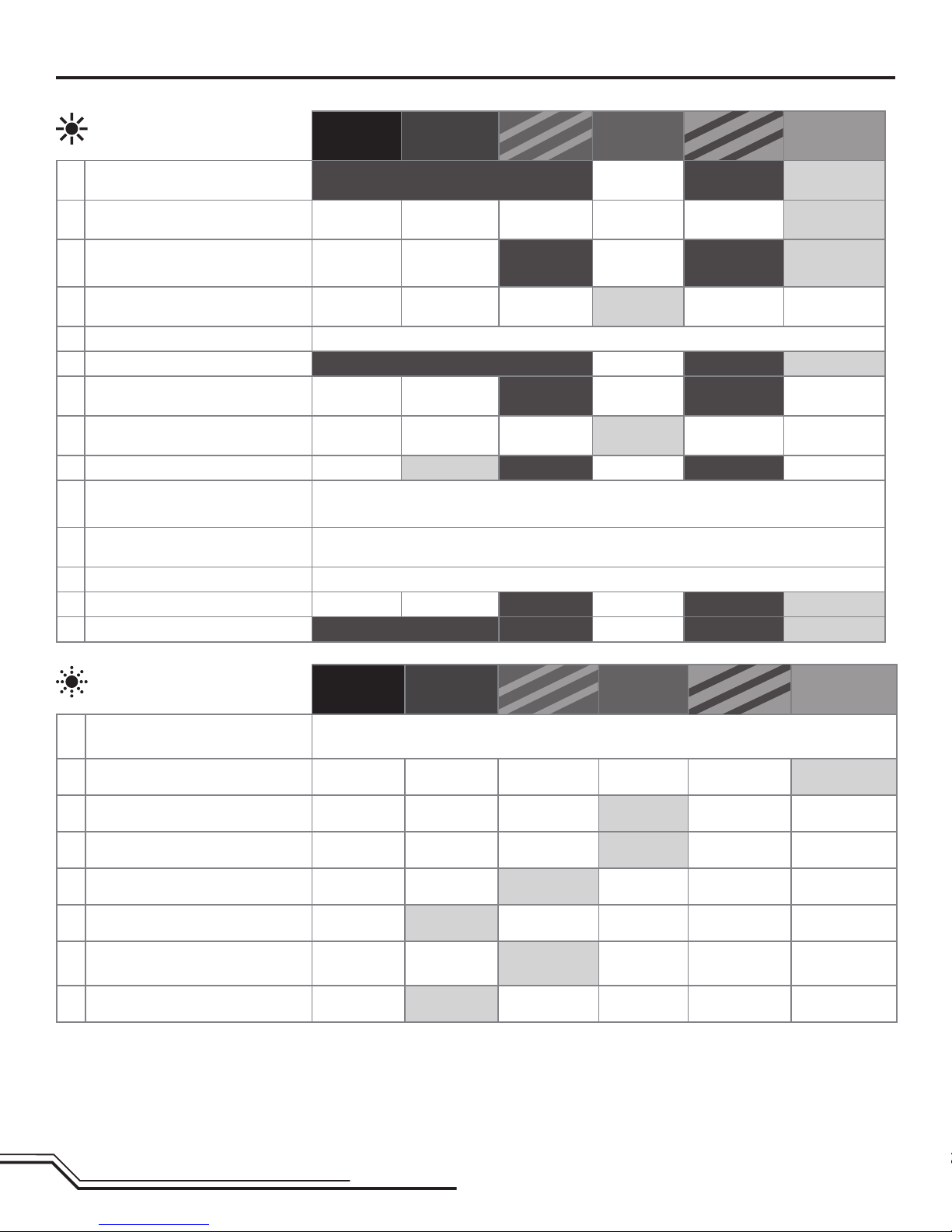
AR7200BX Default Blade 500 X Setup
*The AR7200BX included with your Blade 500 X helicopter is pre-programmed with these default settings. If you perform a factory reset on the included
AR7200BX will default back to these default Blade 500 X helicopter settings.
To perform a Blade 500 X AR7200BX factory reset, enter any Setup menu and press the setup button for 10 seconds. After performing the factory reset, you will
need to re-center the swashplate servos by using setup menu G.
If you update the firmware on the AR7200BX to non-Blade 500 X firmware, all Blade 500 X helicopter default settings will be deleted. You will need to
complete the entire AR7200BX setup process before flying the helicopter again. Please refer to the Spektrum AR7200BX instruction manual.
Status-LED: OFF Purple Red
Flashing Red Solid Blue
Flashing Blue Solid
A Mounting orientation upright
(vertical) at
(horizontal)*
BSwashplate servo - frequency User
defined 50 Hz 65 Hz 120 Hz 165 Hz 200 Hz*
CTail servo - center position pulse
length
User
defined 960 μs 760 μs 1520 μs*
DTail servo - frequency User
defined 50 Hz 165 Hz 270* Hz 333 Hz 560 Hz
ETail servo - rotor endpoints Tailstick-movetorightendpointandwait/leftendpointandwait
FTail - sensor direction normal reversed*
GSwashplate - servo centering Reference
position ELE center
pos. AIL center
pos. PIT center
pos.
HSwashplate - mixer User
defined mechanical 90° 120°* 140° 140°(1=1)
ISwashplate - servo directions nor|rev|rev nor|nor|rev* nor|rev|nor nor|nor|nor
JSwashplate - cyclic pitch
geometry Aileronstick–adjust6°cyclicpitchontherollaxis(bladesalignedwithfuselage)
K Collective pitch range Collectivestickonmaxandminpositionandusetailsticktoadjustdesiredpitch.
Stocksettingsprovide+/-14degreesofcollectivepitch.
LSwashplate - cyclic limit Moveaileron,elevatorandpitchsticks–adjustmaxlimitswithtailstick
MSwashplate - sensor directions rev | rev rev | nor nor | rev nor | nor*
N Pirouette optimization direction normal reversed*
Status-LED: OFF Purple Red
Flashing Red Solid Blue
Flashing Blue Solid
ASwashplate -
cyclic center adjustment
Aileronandelevatorstick–resetwithtailstick
B Control behavior User
defined normal sport pro extreme transmitter*
CSwashplate - pitching up behavior User
defined very low low medium* high very high
DTail - HeadingLock gain User
defined very low low medium* high very high
E Stick deadband User
defined 1 2* 3 4 5
FTail - torque precompensation IX) User
defined off* low - nor high - nor low - rev high - rev
GCyclic response User
defined normal slightly
increased*
increased high very high
HPitch boost User
defined off* low medium high very high
PARAMETER MENU Menu LED is flashing quickly
SETUP MENU Menu LED solid
Firmware version 5003.0.0

13 EN
AR7200BX Fine-tuning and Adjustment
Blade 500 X Troubleshooting Guide
Problem Possible Cause Solution
Helicopter will not bind to the
transmitter (during binding)
Lowightbatteryortransmitterbatteryvoltage Fullychargeorreplacetheightbatteryand/ortransmitterbatteries
AR7200BX is not in bind mode MakesurethebindplugisconnectedtotheAR7200BXBND/DAT
port
Transmitter is not in bind mode Refer to your transmitter's instruction manual for binding instruc-
tions
Transmitter too close to the helicopter during binding
process
Power off the transmitter. Move the transmitter to a larger distance
fromthehelicopter.Disconnectandreconnecttheightbatteryto
the helicopter and follow binding instructions.
Helicopterwillnotlinktothe
transmitter (after binding)
Helicopter is bound to a different model memory
(ModelMatch radios only)
Disconnecttheightbattery.Selectthecorrectmodelmemoryon
thetransmitter.Reconnecttheightbattery
Flight battery/Transmitter battery charge is too low Replace or recharge batteries
AR7200BX will not initialize The helicopter was moved during initialization Lay the helicopter on its side during initialization if windy
The transmitter is powered off Power on the transmitter
Controls are not centered Centerelevator,aileronandruddercontrols.Makesurethethrottle
is at idle
Helicopter will not respond to
the throttle but responds to
other controls
Throttle not at idle and/or throttle trim is too high Lowerthethrottlestickandlowerthethrottletrim
The transmitter is not in normal mode or throttle hold
is on Makesurethetransmitterisinnormalmodeandthrottleholdisoff
The motor is not connected to the ESC or the motor
wires are damaged
ConnectthemotorwirestotheESCandcheckmotorwiresfordam-
age
Flight battery charge is too low Replaceorrechargeightbattery
Throttle channel is reversed Reverse the throttle channel on the transmitter
Helicopterpowerislacking Flight battery has low voltage Fullychargetheightbattery
Flight battery is old or damaged Replacetheightbattery
Flight battery cells are unbalanced Fullychargetheightbattery,allowingthechargertimetobalance
the cells
Excessive current is being drawn through the BEC Checkallservosandthehelicoptermotorfordamage
Tail drive belt tension is not correct. See"CheckingTailDriveBeltTension"inthismanual
AR7200BX Parameter Menu Tips
RefertotheSpektrumAR7200BXmanualtonetunetheBlade500Xtoyour
yingandcontrolstyleviatheAR7200BXparametermenu.
Ifyouwouldliketochangethecontrolbehavioroftheybarlesssystemtoa
pre-defined behavior in the AR7200BX, adjust parameter B (default behavior is
transmitter).
IfyouwouldliketohavethecyclicbehaviortofeelmorelinearORmorelike
aybarredhelicopter,increasethecyclicresponsebyadjustingparameterG
(default is ‘slightly increased’).
RefertotheSpektrumAR7200BXmanualforspecicdetailsoneach
parameter.
Observed Behavior Suggested Adjustment
Cyclic response is too slow or too fast Adjustendpointstotyouryingstyle.Refertoyourtransmitterinstruction
manual for more information
AdjustthecontrolbehaviorparameterintheAR7200BXtotyouryingstyle.
Control inputs feel delayed Increase Dial 2 on the AR7200BX
The helicopter seems to overshoot control input and then return Decrease Dial 2 on the AR7200BX
The helicopter tail stops too abruptly Decrease Dial 3 on the AR7200BX
The helicopter tail does not stop precisely Makesurethetaildrivebelttensionisadjustedcorrectly
Increase the rudder gain in your transmitter
Increase Dial 3 on the AR7200BX
AdjusttherudderheadinglockgainparameterintheAR7200BX

14
EN
What this Warranty Covers
Horizon Hobby, Inc., (Horizon) warrants to the original purchaser that the product purchased
(the “Product”) will be free from defects in materials and workmanship at the date of
purchase.
What is Not Covered
This warranty is not transferable and does not cover (i) cosmetic damage, (ii) damage due
to acts of God, accident, misuse, abuse, negligence, commercial use, or due to improper
use, installation, operation or maintenance, (iii) modification of or to any part of the Product,
(iv) attempted service by anyone other than a Horizon Hobby authorized service center, (v)
Product not purchased from an authorized Horizon dealer, or (vi) Product not compliant with
applicable technical regulations.
OTHER THAN THE EXPRESS WARRANTY ABOVE, HORIZON MAKES NO OTHER WARRANTY
OR REPRESENTATION, AND HEREBY DISCLAIMS ANY AND ALL IMPLIED WARRANTIES,
INCLUDING, WITHOUT LIMITATION, THE IMPLIED WARRANTIES OF NON-INFRINGEMENT,
MERCHANTABILITY AND FITNESS FOR A PARTICULAR PURPOSE. THE PURCHASER
ACKNOWLEDGES THAT THEY ALONE HAVE DETERMINED THAT THE PRODUCT WILL
SUITABLY MEET THE REQUIREMENTS OF THE PURCHASER’S INTENDED USE.
Purchaser’s Remedy
Horizon’s sole obligation and purchaser’s sole and exclusive remedy shall be that Horizon
will, at its option, either (i) service, or (ii) replace, any Product determined by Horizon to be
defective. Horizon reserves the right to inspect any and all Product(s) involved in a warranty
claim. Service or replacement decisions are at the sole discretion of Horizon. Proof of
purchase is required for all warranty claims. SERVICE OR REPLACEMENT AS PROVIDED
UNDER THIS WARRANTY IS THE PURCHASER’S SOLE AND EXCLUSIVE REMEDY.
Limitation of Liability
HORIZON SHALL NOT BE LIABLE FOR SPECIAL, INDIRECT, INCIDENTAL OR CONSEQUENTIAL
DAMAGES, LOSS OF PROFITS OR PRODUCTION OR COMMERCIAL LOSS IN ANY WAY,
REGARDLESS OF WHETHER SUCH CLAIM IS BASED IN CONTRACT, WARRANTY, TORT,
NEGLIGENCE, STRICT LIABILITY OR ANY OTHER THEORY OF LIABILITY, EVEN IF HORIZON
HAS BEEN ADVISED OF THE POSSIBILITY OF SUCH DAMAGES. Further, in no event shall the
liability of Horizon exceed the individual price of the Product on which liability is asserted.
As Horizon has no control over use, setup, final assembly, modification or misuse, no liability
shall be assumed nor accepted for any resulting damage or injury. By the act of use, setup
or assembly, the user accepts all resulting liability. If you as the purchaser or user are not
prepared to accept the liability associated with the use of the Product, purchaser is advised
to return the Product immediately in new and unused condition to the place of purchase.
Law
These terms are governed by Illinois law (without regard to conflict of law principals). This
warranty gives you specific legal rights, and you may also have other rights which vary from
state to state. Horizon reserves the right to change or modify this warranty at any time
without notice.
WARRANTY SERVICES
Questions, Assistance, and Services
Your local hobby store and/or place of purchase cannot provide warranty support or service.
Once assembly, setup or use of the Product has been started, you must contact your local
distributor or Horizon directly. This will enable Horizon to better answer your questions and
service you in the event that you may need any assistance. For questions or assistance,
please visit our website at www.horizonhobby.com, submit a Product Support Inquiry, or call
877.504.0233 toll free to speak to a Product Support representative.
Inspection or Services
If this Product needs to be inspected or serviced and is compliant in the country you live
and use the Product in, please use the Horizon Online Service Request submission process
found on our website or call Horizon to obtain a Return Merchandise Authorization (RMA)
number. Pack the Product securely using a shipping carton. Please note that original boxes
may be included, but are not designed to withstand the rigors of shipping without additional
protection. Ship via a carrier that provides tracking and insurance for lost or damaged
parcels, as Horizon is not responsible for merchandise until it arrives and is accepted at our
facility. An Online Service Request is available at Horizon Hobby Service Center. If you do
not have internet access, please contact Horizon Product Support to obtain a RMA number
along with instructions for submitting your product for service. When calling Horizon, you will
be asked to provide your complete name, street address, email address and phone number
where you can be reached during business hours. When sending product into Horizon, please
include your RMA number, a list of the included items, and a brief summary of the problem.
A copy of your original sales receipt must be included for warranty consideration. Be sure
your name, address, and RMA number are clearly written on the outside of the shipping
carton.
Notice: Do not ship LiPo batteries to Horizon. If you have any issue with a LiPo
battery, please contact the appropriate Horizon Product Support office.
Warranty Requirements
For Warranty consideration, you must include your original sales receipt verifying
the proof-of-purchase date. Provided warranty conditions have been met, your Product
will be serviced or replaced free of charge. Service or replacement decisions are at the sole
discretion of Horizon.
Non-Warranty Service
Should your service not be covered by warranty service will be completed and
payment will be required without notification or estimate of the expense unless
the expense exceeds 50% of the retail purchase cost. By submitting the item for
service you are agreeing to payment of the service without notification. Service estimates are
available upon request. You must include this request with your item submitted for service.
Non-warranty service estimates will be billed a minimum of ½ hour of labor. In addition
you will be billed for return freight. Horizon accepts money orders and cashier’s checks, as
well as Visa, MasterCard, American Express, and Discover cards. By submitting any item to
Horizon for service, you are agreeing to Horizon’s Terms and Conditions found on our website
Horizon Hobby Service Center.
NOTICE: Horizon service is limited to Product compliant in the country of use and
ownership. If non-compliant product is received by Horizon for service, it will be
returned unserviced at the sole expense of the purchaser.
Limited Warranty
Problem Possible Cause Solution
Helicopter will not lift off Main rotor head is not spinning in the correct direc-
tion
Makesurethemainrotorheadisspinningclockwise.Refertothe
motor control test
Transmitter settings are not correct Checkthrottleandpitchcurvesettingsandpitchcontroldirection
Flight battery has low voltage Fullychargetheightbattery
Mainrotorbladesareinstalledbackwards Installthemainrotorbladeswiththethickersideastheleading
edge
Flight battery will not charge Input voltage to the charger is too low Inputvoltagemustbebetween10.6–15VDCwithaminimum10A
current
The battery balance tab is damaged Makesurethebalancetabwiresarefullyseatedinthebalanceplug
Theightbatteryisoverdischarged If any cell voltage drops below 3V, the battery is damaged and must
be replaced.
The helicopter tail spins out of
control Rudder control and/or sensor direction reversed Makesuretheruddercontrolandtheruddersensorareoperatingin
the correct direction
Tail servo is damaged Checktherudderservofordamageandreplaceifnecessary
Inadequate control arm throw Checktheruddercontrolarmforadequatetravelandadjustifnec-
essary
Tail belt is too loose Makesurethetaildrivebelttensionisadjustedcorrectly
Thehelicopterwobblesinight Cyclic gain is too high Decrease Dial 1 on the AR7200BX
Headspeed is too low Increase the helicopter's head speed via your transmitter settings
and/orusingafreshlychargedightpack
Dampers are worn Replace the main rotor head dampers
Blade 500 X Troubleshooting Guide, continued

15 EN
Warranty and Service Contact Information
AMA National Model Aircra Safety Code
Country of Purchase Horizon Hobby Address Phone Number / Email Address
United States of
America
Horizon Service Center
(Electronics and engines) 4105 Fieldstone Rd
Champaign, Illinois, 61822 USA 877-504-0233
Online Repair Request visit: www.horizonhobby.com/service
Horizon Product Support
(All other products) 4105 Fieldstone Rd
Champaign, Illinois, 61822 USA 877-504-0233
productsupport@horizonhobby.com
United Kingdom Horizon Hobby Limited Units 1-4 Ployters Rd
Staple Tye
Harlow, Essex, CM18 7NS, United Kingdom
+44 (0) 1279 641 097
sales@horizonhobby.co.uk
Germany Horizon Technischer Service Christian-Junge-Straße 1
25337 Elmshorn, Germany +49 (0) 4121 2655 100
service@horizonhobby.de
France Horizon Hobby SAS 14 Rue Gustave Eiffel
Zone d’Activité du Réveil Matin
91230 Montgeron
+33 (0) 1 60 47 44 70
infofrance@horizonhobby.com
China HorizonHobby–China Room 506, No. 97 Changshou Rd.
Shanghai, China 200060
+86 (021) 5180 9868
info@horizonhobby.com.cn
Customer Service Information
Country of Purchase Horizon Hobby Address Phone Number / Email Address
United States Sales 4105 Fieldstone Rd
Champaign, Illinois, 61822 USA (800) 338-4639
sales@horizonhobby.com
United Kingdom Horizon Hobby Limited Units 1-4 Ployters Rd
Staple Tye
Harlow, Essex, CM18 7NS, United Kingdom
+44 (0) 1279 641 097
sales@horizonhobby.co.uk
Germany Horizon Hobby GmbH Christian-Junge-Straße 1
25337 Elmshorn, Germany +49 (0) 4121 2655 100
service@horizonhobby.de
France Horizon Hobby SAS 14 Rue Gustave Eiffel
Zone d’Activité du Réveil Matin
91230 Montgeron
+33 (0) 1 60 47 44 70
infofrance@horizonhobby.com
China HorizonHobby–China Room 506, No. 97 Changshou Rd.
Shanghai, China 200060
+86 (021) 5180 9868
info@horizonhobby.com.cn
Effective January 1, 2011
A. GENERAL: A model aircraft is a non-human-carrying aircraft capable of sustained flight
in the atmosphere. It may not exceed limitations of this code and is intended exclusively
for sport, recreation and/or competition. All model flights must be conducted in accor-
dance with this safety code and any additional rules specific to the flying site.
1. Model aircraft will not be flown:
(a) In a careless or reckless manner.
(b) At a location where model aircraft activities are prohibited.
2. Model aircraft pilots will:
(a) Yield the right of way to all man carrying aircraft.
(b) See and avoid all aircraft and a spotter must be used when appropriate. (AMA
Document #540-D-See and Avoid Guidance.)
(c) Not fly higher than approximately 400 feet above ground level within three (3)
miles of an airport, without notifying the airport operator.
(d) Not interfere with operations and traffic patterns at any airport, heliport or
seaplane base except where there is a mixed use agreement.
(e) Not exceed a takeoff weight, including fuel, of 55 pounds unless in compliance
with the AMA Large Model Aircraft program. (AMA Document 520-A)
(f) Ensure the aircraft is identified with the name and address or AMA number of the
owner on the inside or affixed to the outside of the model aircraft. (This does not
apply to model aircraft flown indoors).
(g) Not operate aircraft with metal-blade propellers or with gaseous boosts except
for helicopters operated under the provisions of AMA Document #555.
(h) Not operate model aircraft while under the influence of alcohol or while using
any drug which could adversely affect the pilot’s ability to safely control the
model.
(i) Not operate model aircraft carrying pyrotechnic devices which explode or burn, or
any device which propels a projectile or drops any object that creates a hazard
to persons or property.
Exceptions:
• FreeFlightfusesordevicesthatburnproducingsmokeandaresecurely
attached to the model aircraft during flight.
• Rocketmotors(usingsolidpropellant)uptoaG-seriessizemaybeused
provided they remain attached to the model during flight. Model rockets
may be flown in accordance with the National Model Rocketry Safety
Code but may not be launched from model aircraft.
• OfciallydesignatedAMAAirShowTeams(AST)areauthorizedtouse
devices and practices as defined within the Team AMA Program Docu-
ment (AMA Document #718).
(j) Not operate a turbine-powered aircraft, unless in compliance with the AMA turbine
regulations. (AMA Document #510-A).

16
EN
AMA National Model Aircra Safety Code, continued
Compliance Information for the European Union
Declaration of Conformity
(in accordance with ISO/IEC 17050-1)
No. HH2012041903
Product(s): Blade 500 X BNF
Item Number(s): BLH4080
Equipment class: 1
The object of declaration described above is in conformity with the require-
ments of the specifications listed below, following the provisions of the
European R&TTE directive 1999/5/EC, EMC Directive 2004/108/EC and LVD
Directive 2006/95/EC:
EN 301 489-1 V1.7.1: 2006
EN 301 489-17 V1.3.2: 2008
EN 60950-1:2006+A11
EN55022: 2010
EN55024: 2010
Signed for and on behalf of:
Horizon Hobby, Inc.
Champaign, IL USA
April 19, 2012
Instructions for disposal of WEEE by users in the European
Union
This product must not be disposed of with other waste. Instead,
it is the user’s responsibility to dispose of their waste equipment
by handing it over to a designated collections point for the recy-
cling of waste electrical and electronic equipment. The separate
collection and recycling of your waste equipment at the time of
disposal will help to conserve natural resources and ensure that
it is recycled in a manner that protects human health and the environment.
For more information about where you can drop off your waste equipment for
recycling, please contact your local city office, your household waste disposal
service or where you purchased the product.
Steven A. Hall
Vice President
InternationalOperationsandRiskManagement
Horizon Hobby, Inc.
3. Model aircraft will not be flown in AMA sanctioned events, air shows or model demon-
strations unless:
(a) The aircraft, control system and pilot skills have successfully demonstrated all
maneuvers intended or anticipated prior to the specific event.
(b) An inexperienced pilot is assisted by an experienced pilot.
4. When and where required by rule, helmets must be properly worn and fastened. They
must be OSHA, DOT, ANSI, SNELL or NOCSAE approved or comply with comparable
standards.
B. RADIO CONTROL (RC)
1. All pilots shall avoid flying directly over unprotected people, vessels, vehicles or structures
and shall avoid endangerment of life and property of others.
2. A successful radio equipment ground-range check in accordance with manufacturer’s
recommendations will be completed before the first flight of a new or repaired model
aircraft.
3. At all flying sites a safety line(s) must be established in front of which all flying takes
place (AMA Document #706-Recommended Field Layout):
(a) Only personnel associated with flying the model aircraft are allowed at or in front of
the safety line.
(b) At air shows or demonstrations, a straight safety line must be established.
(c) An area away from the safety line must be maintained for spectators.
(d) Intentional flying behind the safety line is prohibited.
4. RC model aircraft must use the radio-control frequencies currently allowed by the Federal
Communications Commission (FCC). Only individuals properly licensed by the FCC are
authorized to operate equipment on Amateur Band frequencies.
5. RC model aircraft will not operate within three (3) miles of any pre-existing flying site
without a frequency-management agreement (AMA Documents #922-Testing for RF
Interference; #923- Frequency Management Agreement)
6. With the exception of events flown under official AMA Competition Regulations, excluding
takeoff and landing, no powered model may be flown outdoors closer than 25 feet to any
individual, except for the pilot and the pilot’s helper(s) located at the flight line.
7. Under no circumstances may a pilot or other person touch a model aircraft in flight while
it is still under power, except to divert it from striking an individual. This does not apply to
model aircraft flown indoors.
8. RC night flying requires a lighting system providing the pilot with a clear view of the
model’s attitude and orientation at all times.
9. The pilot of a RC model aircraft shall:
(a) Maintain control during the entire flight, maintaining visual contact without en-
hancement other than by corrective lenses prescribed for the pilot.
(b) Fly using the assistance of a camera or First-Person View (FPV) only in accordance
with the procedures outlined in AMA Document #550.
Please see your local or regional modeling association’s guidelines for proper, safe
operation of your model aircraft.

17 DE
Alters Empfehlung: Nicht für Anfängerpiloten unter 14 Jahren. Das ist kein Spielzeug.
WARNUNG:LesenSiedieGESAMTEBedienungsanleitung,umsichvorInbetriebnahmemitdenFunktionendesProduktsvertrautzumachen.Einenichtordnungsgemäße
BedienungdesProduktskanndasProduktsundpersönlichesEigentumschädigenundschwereVerletzungenverursachen.
DiesesisteinanspruchvollesHobbyProduktfürdenfortgeschrittenenHubschrauberpilotenmitErfahrungvonPitchgesteuerten(CCPM)Hubschraubern((CyclicCollec-
tive Pitch Mixing oder Collective Pitch Helicopter) wie zum Beispiel dem Blade SR oder dem Blade mCP X. Es muss mit Vorsicht und Umsicht bedient werden und erfordert einige
mechanischeGrundfertigkeiten.
DiesisteinhochentwickeltesProduktfürdenHobbygebrauch.EsmussmitVorsichtundUmsichtbedientwerdenunderforderteinigemechanischeGrundfertigkeiten.Wirddas
Produktnichtsicherundumsichtigverwendet,sokönntenVerletzungenoderSchädenamProduktoderanderemEigentumentstehen.DiesesProduktistnichtfürdenGebrauch
durchKinderohnedirekteAufsichteinesErwachsenenvorgesehen.VersuchenSienicht,dasProduktohneZustimmungvonHorizonHobby,Inc.zuzerlegen,mitnicht-kompatiblen
Komponentenzuverwendenoderbeliebigzuverbessern.DiesesHandbuchenthältSicherheitshinweisesowieAnleitungenzuBetriebundWartung.Esistunerlässlich,dassSie
alleAnleitungenundWarnungenindiesemHandbuchvordemZusammenbau,derEinrichtungoderderInbetriebnahmelesenunddiesebefolgen,umeinekorrekteBedienungzu
gewährleistenundSchädenbzw.schwereVerletzungenzuvermeiden.
DiefolgendeBegriffewerdenindergesamteProduktliteraturverwendet,umdieGefährdungsstufenimUmgangmitdemProduktzudenieren:
DerZweckderSicherheitssymboleistesIhreAufmerksamkeitaufmöglicheGefahrenzulenken.DieSymboleundihreErklärungenerfordernihresorgfältigeAufmerksamkeitund
Verstehen.DieSymboleeliminierennichtdieGefahr.DieAnweisungenundWarnungenersetzennichtangemesseneundkorrekteUnfallverhütungsmaßnahmen.
HINWEIS:VerfahrenkönnenbeinichtordnungsgemäßerDurchführungwomöglichSchädenanphysischemEigentumUNDgeringfügigeoderkeineVerletzungenverursachen.
ACHTUNG:VerfahrenkönnenbeinichtordnungsgemäßerDurchführungwomöglichSchädenanphysischemEigentumUNDschwereVerletzungenverursachen.
WARNUNG:VerfahrenkönnenbeinichtordnungsgemäßerDurchführungmöglicherweiseSchädenanEigentum,KollateralschädenUNDschwereVerletzungenbiszumTotODER
höchstwahrscheinlichoberächlicheVerletzungenverursachen.
Zusätzliche Sicherheitsmaßnahmen und Warnungen
• HaltenSiestetsinallenRichtungeneinenSicherheitsabstandzuIhremModellein,umKollisionenundVerletzungenzuvermeiden.DiesesModellwirdübereinFunksignalge-
steuert.Funksignalekönnenvonaußerhalbgestörtwerden,ohnedassSiedaraufEinussnehmenkönnen.DieskannzueinemvorübergehendenVerlustderSteuerungskontrolle
führen.
• StellenSieimmersicher,dassSievollständigdieKontrollendesSendersundIhrenEinußaufdieBewegungdesHubschrauberverstandenhaben.
• BetreibenSieIhrModellstetsaufoffenenGeländen,weitabvonAutomobilen,VerkehrundMenschen.
• BefolgenSiedieAnweisungenundWarnungenfürdiesesProduktundjedwedesoptionalesZubehörteil(Ladegeräte,wiederauadbareAkkusetc.)stetssorgfältig.
• HaltenSiesämtlicheChemikalien,KleinteileundelektrischeKomponentestetsaußerReichweitevonKindern.
• FeuchtigkeitbeschädigtdieElektronik.VermeidenSiedenWasserkontaktallerKomponenten,diedafürnichtspeziellausgelegtundentsprechendgeschütztsind.
• HaltenSiediesesProduktstetsausserReichweitevonKindern.LagernSiediesesProduktimmerausserhalbderReichweitevonKindern.
• HaltenSiestetsihrHaarüberdenSchulterngesichert,dassessichnichtindenBlätternverfangenkann.
• BetreibenundwartenSiediesesProduktimmerbeiTageslicht.
• StellenSievordemBetriebimmersicherdassalleBefestigungengesichertsind.
• LagernSiediesesProduktimmeraneinemsicherentrockenenOrt.
• BerührenSienichtdenMotor,daerwährenddesBetriebesextremheißwerdenkann.
• FliegenSiedenHubschraubernichtIndoor(inRäumen,GebäudenoderHallen)
• VertrauenSienichtausschließlichaufdieSicherheitsmechanismendieimSenderundEmpfängereingebautsind.VersichernSiesichimmer,dassSiedasProduktundwieeszu
betreiben ist verstehen.
• VerwendenSiefürdiesesProduktnurvonHorizonzugelasseneTeileundZubehör.
• NehmenSieniemalseinElementdesModellsinIhrenMund,dadieszuschwerenVerletzungenodersogarzumTodführenkönnte.
• BetreibenSieIhrModellniemalsmitSenderbatterien.
• SchließenSiekeinAkkuanwennSiedasProduktnichttestenoderinBetriebnehmen.
• BeiderWartungoderdemBetriebdesProduktdürfenSiekeinehängendeoderloseGegenständeanihrerPersonhaben.
• SprühenSieniemalsGlasreinigeroderandereFlüssigkeitenaufdiesesProdukt.
• BetreibenSiediesesProduktnichtwennSiemüdesind,sichunwohlfühlen,MedikamentenehmendieihreReaktionsfähigkeitbeeinussen,oderunterdemEinußvonDrogen
oderAlkoholstehen.
• BetreibenSiediesesProduktnieimRegenoderschlechtenWetter.
• FührenSieniemalsWartungarbeitenmitindemHubschraubereingesetztemAkkudurch.
HINWEIS
AllenAnweisungen,GarantienundanderenzugehörigenDokumentensindÄnderungennachErmessenvonHorizonHobby,Inc.vorbehalten.AktuelleProduktliteraturndenSieauf
horizonhobby.comimSupport-AbschnittfürdasProdukt.
Begriffserklärung
WARNUNG: DasnichtbefolgendieserAnweisungenkannzuBeschädigungdesHubschraubers,Sachbeschädigungenund/oderKörperverletzungenbishinzumTodführen.
ACHTUNG:NehmenSiekeineÄnderungenoderEinstellungenandemProduktvordienichtinderBedienungsanleitungabgebildetsind.
WARNUNG: Das ist großer Hubschrauber mit Rotorblättern die mit hoher Drehzahl drehen. Seien Sie extrem aufmerksam und benutzen ihren gesunden Men-
schenverstand wenn Sie dieses Produkt warten oder nutzen. Sollte Ihnen eine beliebige Funktion oder Vorgang der in dieser Anleitung beschrieben wird nicht
klar sein betreiben Sie das Produkt NICHT. Kontaktieren Sie den technischen Service von Horizon zur Unterstützung.
Sicherheitsalarm: ZeigteineWarnungoderVorsichtmaßregelan.HieristAufmerksamkeiterforderlichumernsteKörperverletzungenzuvermeiden.
WARNUNG: Halten Sie mit dem Hubschrauber mindestens 13 Meter Abstand zu sich selbst und anderen.

18
DE
Inhaltsverzeichnis Blade 500 X Spezifikationen
Länge 33.5 in (850mm)
Höhe 11.8 in (300mm)
Hauptrotordurchmesser 38.2 in (970mm)
Heckrotordurchmesser 7.8 in (198mm)
Fluggewicht 3.88 lb (1760 g)
Komponenten
Motor 520H Brushless Aussenläufer 1320Kv (eingebaut)
Regler/ESC 70 A Brushless Regler (eingebaut)
Akku 6S 22.2V 2900mAh 30C Li-Po Akku (included)
Ladegerät DC LiPo Balancer Ladegerät (included)
Flybarless Unit Spektrum AR7200BX and remote receiver
with BeastX™ technology (eingebaut)
Servos
Taumelscheibe
Spektrum S300 (eingebaut)
Heckrotorservo Spektrum S400G (eingebaut)
Sie können Ihr Produkt online unter www.bladehelis.com registrieren.
LadendesFlugakkus..................................................................................19
FarbcodeszumAkkuladestatus...................................................................19
WarnungenzumLadenvonAkkus ..............................................................19
Programmieren des Senders.......................................................................20
Einrichten des Senders ...............................................................................21
BindenvonSenderundEmpfänger.............................................................23
Throttle Hold...............................................................................................23
EinsetzendesFlugakkus.............................................................................23
ÜberprüfenderSteuerkontrollen.................................................................24
Niederspannungsabschaltung (LVC) ............................................................25
Richtlinien und Warnungen zum Fliegen......................................................25
EinstellungdesGyro-Gain(Gyro-Empndlichkeit)........................................26
Einstellen der Riemenspannung..................................................................26
InspektionnachdemFlugundWartung ......................................................26
AR7200BX-Standard-SetupfürBlade500X................................................27
TippszumAR7200BX-Parametermenü .......................................................28
AR7200BX Feinabstimmung und Anpassung...............................................28
Blade 500 X - Leitfaden zur Fehlerbehebung...............................................28
Garantie-undService-Kontaktinformationen...............................................30
Kundendienstinformationen ........................................................................30
RechtlicheInformationenfürdieEuropäischeUnion....................................31
Ersatzteile...................................................................................................63
Optionale Bauteile.......................................................................................65
500 X BLH4080
WARNUNG:DieserHubschrauberistmitCarbonrotorblätternausgestattetdiemitsehrhoher
Drehzahldrehen.FolgenSieimmerallenSicherheitsvorkehrungenindieserBedienungsanleitung.

19 DE
Laden des Flugakkus
Laden des Akkus
1.LadenSienurkühleundeinwandfreieAkkusauf.PrüfenSiedenAkku,umsicherzustellen,dassernichtbeschädigtist,z.B.obangeschwollen,verbogen,
gebrochenoderpunktiert.
2.SchließenSiedasLadegerätaneine12-V-Stromquelle(mindestens10A)an.AchtenSiedabeiaufdiePolarität.
3. Die LADESTATUS-LED leuchtet durchgehend rot.
4.SchließenSiedenBalancersteckerdesAkkusandasLadegerätan.DerBalance-SteckerverhinderteinePolaritätsumkehr.
5.DieZELLSTATUS-LEDsleuchtendurchgehendgrünodergelb,unddieLADESTATUS-LEDleuchtetdurchgehendrot,wennderAkkuaufgeladenwird.
6. Der Ladevorgang ist abgeschlossen, wenn alle LEDs durchgehend rot leuchten.
7.TrennenSiedenAkkuimmersofortnachabgeschlossenemLadevorgangvomLadegerät.
DerBlade500XBNFwirdmiteinemDC-Balancer-Ladegerätundeinem6S
LiPo-Akkugeliefert.VerwendenSienurvonHorizonHobbyzugelasseneAk-
kupacksundLadegeräte,diemitdiesemProduktkompatibelsind.
LassenSiedenAkkuunddasLadegerätwährenddesLadevorgangsnicht
unbeaufsichtigt.EineMissachtungderAnweisungenkannzuFeuerentwicklung
führen.VergewissernSiesich,dasssichderAkkuwährenddesAuadensauf
einerhitzebeständigenOberächebendet.LadenSiedenFlugakkuauf,bevor
SiedenHubschrauberbindenbzw.Kontrolltestsdurchführen.
DC-LiPo-Balancer-Ladegerät - Eigenschaften
•Lädt6-Zellen-Lithium-Polymer-Akkupacks
•Ladestrom2,5A
•LED-Ladestatusanzeige
•LED-BalanceAnzeige
•12-V-Krokodilklemmen-Eingangskabel
Spezifikationen
•Eingangsleistung:mind.10Abei10,6bis15VDC
•Lädt6-Zellen-Lithium-Polymer-AkkupacksbeieinerMindestkapazitätvon
2500 mAh
6S 22.2V 2900mAh Li-Po Akku Pack
DerBlade500X6SLiPoAkkuistzumsicherenladenmitdemimLieferumfang
enthaltenenLadegerätmiteinemBalanceranschlußausgestattet.DerimLief-
erumfangenthalteneAkkukannsichermitbiszu3C(8,7A)geladenwerden.
WARNUNG: Bevor Sie mit dem Ladevorgang beginnen, muss der
Balance-SteckermitdemrichtigenAnschlussihresLadegerätsverbun-
den sein.
Farbcodes zum Akkuladestatus
Zellstatus LED Ladestatus LED Anweisung
Aus Durchgehend rot DasAkku-LadegerätistaneinerStromquelleangeschlossen.DerLiPo-Akkuistnichtangeschlossen.
Gelb Durchgehend rot DerLiPo-Akkuistangeschlossen.DasLadegerätbalanciertdieZellendesAkkupacks.
Grün Durchgehend rot DerLiPo-Akkuistangeschlossenundwirdgeladen
Rot Durchgehend rot DerLiPo-AkkuistangeschlossenundderLadevorgangabgeschlossen
Aus Blinkendrot KeinLiPo-Akkuangeschlossen:DieSpannungliegtaußerhalbdesEingangsspannungsbereichs
LiPo-Akkuangeschlossen:DieSpannungzumindesteinerAkkuzelleliegtunter2,6V
CAUTION: Only use a charger specifically designed to charge a Li-Po battery. Failure to do so could result in fire causing injury or property damage.
CAUTION: Never exceed the recommended charge rate.
ACHTUNG: EineFehlhandhabungvonLiPo-AkkuskannzuFeuer,Verlet-
zungenund/oderSachschädenführen.
• MitdemGebrauch,demAuadenbzw.derVerwendungdesenthaltenen
LiPo-AkkusübernehmenSiealleRisiken,diemitLithiumakkusverbunden
sind.
• WennderAkkuanzuschwellenodersichaufzublähenbeginnt,stellenSie
dessen Verwendung umgehend ein. Tritt dies beim Laden oder Entladen auf,
brechenSiedenVorgangabundentfernenSiedenAkku.WennSieeinsich
aufblähenderoderanschwellenderAkkuweiterhinverwenden,auadenoder
entladen,kanndieseszuFeuerführen.
• WährenddesTransportsodervorübergehenderLagerungsolltedieTempera-
tur4°Cnichtunterschreitenund48°Cnichtüberschreiten.BewahrenSie
denAkkuoderdasModellnichtineinemAutoaufundvermeidenSiedirekte
Sonneneinstrahlung.IneinemheißenAutokannderAkkubeschädigtwerden
oder sogar Feuer fangen.
• LadenSieAkkusbzw.BatterienstetsineinerUmgebungentferntvon
entzündbarenMaterialienauf.
• ÜberprüfenSieAkkusimmervordemLadenundladenSieniemalsbeschä-
digteAkkusauf.
• VerwendenSienurfürLiPoAkkusgeeigneteLadegeräte.DasLadendes
Akkusmiteinemnicht-kompatiblenLadegerätkannzuFeuerundfolglichzu
Verletzungenund/oderSachschädenführen.
• ÜberwachenSieimmerkonstantdieTemperaturdesAkkupacksbeimLaden.
• TrennenSieimmerdenAkkunachdemLadenvomLadegerätundlassen
dasLadegerätvorweiteremGebrauchabkühlen.
• Entladen Sie LiPo-Zellen nicht unter 3 V unter Last.
• DeckenSieWarnhinweisenichtmitKlettstreifenab.
• LassenSieAkkuswährenddesLadensniemalsunbeaufsichtigt.
• LadenSieAkkusniemalsaußerhalbderempfohlenenGrenzenauf.
• LadenSienurAkkusdiekühlgenugzumanfassensind.
• VersuchenSieniemalsdasLadegerätzuverändernoderauseinanderzu
nehmen.
• ErlaubenSieesniemalsMinderjährigenAkkuszuladen.
• LadenoderlagernSieniemalsAkkusinextremheißenoderkaltenPlatzen
(empfohlenerTemperaturbereich4-49°)oderindirektemSonnenlicht.
Warnungen zum Laden von Akkus

20
DE
Spektrum DX6i
POS-0POS-0 POS-1
Modeltyp Umkehr Swash Type/
Taumelscheibe Timer
HELI THRO—N 1 Servo 90 Degree Type—Down
AILE—N Time—4:00
ELEV—R Switch—
Trainer
RUDD—R
GYRO—N
PITC—R
Modeltyp Taumelscheibentyp Input Select
HELI 1 Servo Norm AUX2 GEAR
INH GYRO
D/R Expo
AILE 0 100% INH
ELEV 0 100% INH
RUDD 0 100% INH
AILE 1 85% INH
ELEV 1 85% INH
RUDD 1 85% INH
AUTO D/R EXP
NORM INH
ST-1 INH
ST-2 INH
HOLD INH
AILE ELEV RUDD
EXP LIN EXP LIN EXP LIN
D/R 100% D/R 100% D/R 100%
AILE ELEV RUDD
EXP LIN EXP LIN EXP LIN
D/R 85% D/R 85% D/R 85%
TRAVEL ADJUST
THRO 100%
AILE 100%
ELEV 100%
RUDD 100%
GYRO 100%
PITC 100%
TRAVEL ADJUST/WEG
THRO AILE
H 100% L 100%
L 100% R 100%
ELEV RUDD
D 100% L 100%
U 100% R 100%
GEAR PIT
+ 100% H 100%
- 100% L 100%
AUX2
+ 100%
- 100%
SUB-TRIM*
THRO 0
AILE 0*
ELEV 0*
RUDD 0*
GYRO 0
PITC 0
SUB-TRIM*
THRO 0
AILE 0*
ELEV 0*
RUDD 0*
GEAR 0
PITC 0
AUX2 0
GYRO
Rate SW-F. Mode
0 68.0% NORM 0
1 67.0% STUNT 1
GYRO SENS
AUTO F. MODE
RATE NORM 0
0 79.0% STNT 1
1 71.0% HOLD 0
THRO HOLD
HOLD POS 0.0%
SW RUDD D/R
TIMER/UHR
DOWN-T 4:00
SWASH MIX/
TAUMELSCHEIBENMISCHER
INH
REVERSING SW/UMKEHR
THRO AILE ELEV RUDD GEAR PIT AUX2
N N R R N N N
THRO CUR /GAS KURVE
L 2 3 4 H
NORM 0% 30% 60% 60% 60%
STUNT 100% 100% 100% 100% 100%
HOLD 10% 10% 10% 10% 10%
THRO CURVE/GAS KURVE
L 1 2 3 H
NORM 0% 30% 60% 60% 60%
ST-1 100% 100% 100% 100% 100%
ST-2 100% 100% 100% 100% 100%
PITC CUR/PITCH KURVE
L 2 3 4 H
NORM 30% 40% 50% 75% 100%
STUNT 0% 25% 50% 75% 100%
HOLD 0% 25% 50% 75% 100%
PITCH CURVE/PITCH KURVE
L 1 2 3 H
NORM 30% 40% 50% 75% 100%
ST-1 0% 25% 50% 75% 100%
ST-2 0% 25% 50% 75% 100%
HOLD 0% 25% 50% 75% 100%
SWASH MIX/
TAUMELSCHEIBENMISCHER
INHIBIT *Verwenden Sie mit dem AR7200BX niemals Sub Trimms auf AILE, ELEV oder RUDD
*Verwenden Sie mit dem AR7200BX niemals Sub Trimms auf AILE, ELEV oder RUDD
SETUP LIST/EINSTELLUNGEN
SYSTEM LIST/SYSTEMLISTE
ADJUST LIST/
PROGRAMMIEREINSTELLUNGEN
ADJUST LIST/PROGRAMMIEREINSTELLUNGEN
Spektrum DX7/DX7se
Programmieren des Senders
Sie müssen Ihren Sender zuerst programmieren, bevor Sie den Hubschrauber binden oder fliegen können. Die Werte, die Sie zum Programmieren Ihres
SendersfürSpektrumDX6i,DX7/DX7se,DX7sundDX8Empfängerbenötigen,sinduntenangeführt.DieSpektrum-ModelldateienfürAirWare™Senderstehen
auchonlineinderSpektrumCommunityzumDownloadzurVerfügung.
ACHTUNG:WennSieeinenFutaba-SendermiteinemSpektrumDSM-Modulverwenden,müssenSiedenGaskanalreversieren(umkehren)unddanach
dasSystemneubinden.LesenSiebittefürdenBindevorgangundprogrammierenderFailsafeeinstellungendieBedienungsanleitungdesSpektrum
Modules.ZumreversierendesGaskanalslesenSiebitteinderAnleitungdesFutabaSendersnach.
This manual suits for next models
1
Table of contents
Languages:
Other BNF Toy manuals

BNF
BNF Blade 130 S User manual

BNF
BNF INVERZA 280 User manual

BNF
BNF P-40 Warhawk User manual

BNF
BNF UMX Carbon Cub SS User manual

BNF
BNF F4U-1A Corsair User manual

BNF
BNF B-17G User manual

BNF
BNF Carbon-Z Cub User manual

BNF
BNF Blade Nano CPX User manual

BNF
BNF 120 SR User manual

BNF
BNF Viking 12 280 User manual

BNF
BNF EDGE 540QQ 280 User manual

BNF
BNF UMX MiG 15 DF User manual

BNF
BNF Blade 500 3D User manual

BNF
BNF UMX Radian User manual

BNF
BNF UMX Yak 54 180 User manual

BNF
BNF UMX Habu S DF180 User manual

BNF
BNF Blade mCP User manual

BNF
BNF Blade Fusion 270 User manual

BNF
BNF Blade Theory W User manual

BNF
BNF Blade 500 3D User manual


