Boart Longyear S250 Quick start guide
S250 ROCKDRILL
PARTS & SERVICE MANUAL

S250 ROCKDRILL | PARTS & SERVICE MANUAL January, 2021
1
Certificate of Conformance
Each drill is supplied with a certificate of conformance, signed by
the assembly mechanic. It lists the drill’s actual test results at
the time of assembly. The certificate also describes the start-up
and lubrication procedures, and provides a brief health and
safety notice.
Important Safety Information
DO NOT START or OPERATE THE MACHINE until you have
READ this manual and UNDERSTAND the contents.
Non-authorised personnel MUST NOT under any circumstances
attempt to operate or repair the machine. This is a violation of
warranty.
Safety precautions listed in the manual are intended to alert the
operator and mechanics to physical dangers inherent in various
phases of operating and maintaining drilling equipment of this
kind.
Safe work procedures must always be the primary consideration
of all personnel when operating or maintaining the drill rig for
intended applications. Do not use in awkward or un-intended
applications. The Safety Precautions listed herein are not
intended to be exhaustive.
Operation of hand-held vibratory equipment should be restricted
to short intervals. For extended drilling applications, drill-rig-
mounted rockdrills are recommended.
HAZARD SIGNAL WORDS AND WARNINGS:
Hazard signal words are used throughout this manual. They
appear in the narrow left-hand column of several pages, and
with their additional text description, are intended to alert the
reader to the existence and relative degree of the hazard.
The signs DANGER, WARNING, CAUTION, and NOTICE are
defined as follows:
Indicates an imminently hazardous situation,
which if not avoided, will result in serious
injury.
The safety alert symbol is used to warn of
potential personal injury hazards.

S250 ROCKDRILL | PARTS & SERVICE MANUAL January, 2021
2
Indicates a potentially hazardous situation,
which if not avoided, could result in serious
injury.
Indicates a potentially hazardous situation,
which if not avoided, may result in minor or
moderate injury.
Is used to make people aware of situations, and
gives hints for operation and maintenance,
which are important, but not hazard related. It
generally indicates an Operational Aid.
•The purchaser must provide proper training to ensure the
safety of all operators. Failure to provide training may result
in serious injury or death.
•Use only qualified service technicians. Failure to do so could
cause severe damage to the machine or the operator and
will void your warranty.
•Operating this piece of equipment without proper Personal
Protective Equipment could result in personal injury. Always
wear Personal Protective Equipment –i.e. hard hat,
industrial safety glasses, hearing protection, steel-toed
boots, and gloves. Heavy-use cut and impact, vibration
resistant gloves are recommended when working on or
operating the rockdrill.
•Operating this piece of equipment without proper hearing
protection may result in permanent hearing loss (dependent
on duration of exposure). For best protection from noise,
use both ear plugs and earmuffs simultaneously. A proper
hearing conservation program is the only effective means of
avoiding hearing damage when operating drills with
percussive power greater than 1 kW.
•Drilling can result in flying particles that may cause eye
injuries (always wear industrial safety glasses).
•ISOLATE all energy sources before servicing equipment.
•Apply safe lifting procedures and two-person lifts when
manually handling the rockdrill.
•Ensure that the drill, accessories, and all actions always
comply with applicable site and local health and safety
regulations.

S250 ROCKDRILL | PARTS & SERVICE MANUAL January, 2021
3
•Never climb on top of the machine.
•Keep clear of rotating drill steel. Never wear any loose
clothing that could become entangled with the machine.
•Be aware that sliding and tilting parts can cause pinch and
crush points.
•Do not operate this piece of equipment while under the
influence of drugs, alcohol, or medication.
•Always keep your work area clean. Avoid dangerous
working environments.
•Be aware of the operating zones and recommended areas
for safe operation. Keep visitors a safe distance away from
the work area.
•Prepare proper tools and equipment. Always use the correct
tool for the job. Improper or homemade tools can cause
injury or machine damage and will void your warranty.
•Use only Boart Longyear replacement parts. Failure to do
so could cause severe damage to the machine or the
operator and will void your warranty.
•Do not change or alter the drill, its components, optional
equipment, or accessories without prior approval from Boart
Longyear. Unauthorized alterations will void the warranty,
render the equipment unsafe, or result in decreased
performance.
•Prolonged hand contact with vibrating machines may cause
Hand Arm Vibration Syndrome (HAVS or “white knuckle”
disease). Anti-Vibration gloves are recommended.
Dependent on vibration level and duration of exposure.
HAVS may cause:
1. Painful fingers, triggered by cold or wet conditions
2. Loss of sense of touch and temperature
3. Numbness and tingling
4. Loss of grip strength
5. Loss of manual dexterity
•The purchaser must ensure safe application of this
equipment for all users, based on total daily exposure to a
vibration magnitude of 20-25 m/s2. This includes but is not
limited to:
1. Limited daily operating time for each operator of this
equipment, based on the vibration magnitude above

S250 ROCKDRILL | PARTS & SERVICE MANUAL January, 2021
4
and all relevant regional regulations and guidelines
for vibratory equipment.
2. Regular or daily health assessments of each operator
including challenging for HAVS symptoms.
Affirmative responses to any of the following
questions may indicate a risk and requires
eliminating exposure and immediate medical referral:
i. Have your fingers gone white on exposure to
cold?
ii. Have you had any tingling or numbness in
your fingers after using vibrating equipment?
iii. Are you experiencing any problems with
muscles or joints in your hand or arms?
iv. Do you have any difficulty picking up small
objects such as screws or nails?
Operating a rockdrill without lubricant or with incorrect lubricant
can cause EXTENSIVE DAMAGE to the working parts of this
machine. NO CLAIM AGAINST PRODUCT WARRANTY will be
considered by the manufacturer if these procedures have not
been followed. NO CLAIM AGAINST PRODUCT WARRANTY
will be considered by the manufacturer if Boart Longyear
replacement parts are not used in repair. All rockdrill repairs
should be performed by properly trained and equipped service
technicians. Failure to adhere to these requirements will void
your warranty.
S250 ROCKDRILL | PARTS & SERVICE MANUAL January, 2021
5
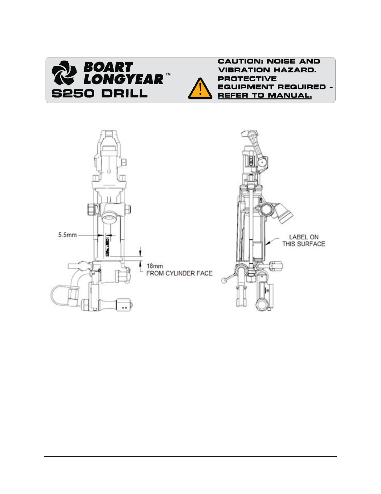
WARNING SIGNS AND SAFETY LABELS:
Figure 1. Caution Label
Figure 2. S250 Standard Caution Label Location
S250 ROCKDRILL | PARTS & SERVICE MANUAL January, 2021
6
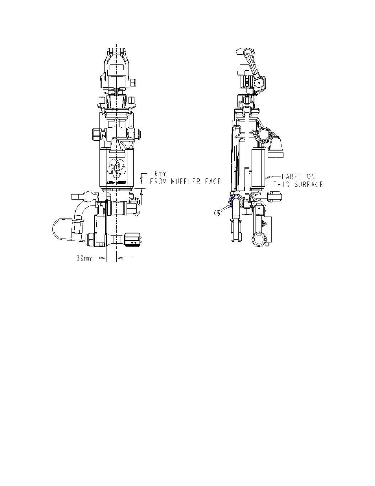
Figure 3. S250 Muffled Caution Label Location

S250 ROCKDRILL | PARTS & SERVICE MANUAL January, 2021
7
TABLE OF CONTENTS
Chapter 1: Introduction and General Information....................................................................... 9
1.1 Introduction.............................................................................................................. 9
1.2 Standard Warranty Policy .......................................................................................10
1.3 Ordering Parts.........................................................................................................12
1.4 Returning Parts.......................................................................................................12
1.5 General Description ................................................................................................13
1.6 Features..................................................................................................................13
Chapter 2: Maintenance Procedures........................................................................................14
2.1 Rockdrill Repair Shop .............................................................................................14
2.1.1 Recommended Workshop Set-Up....................................................14
2.1.2 Recommended Tools and Equipment..............................................14
2.2 S250 Tool Kit..........................................................................................................15
2.3 General Maintenance Overview..............................................................................17
Chapter 3: S250 Jackleg/Sinker Drill Maintenance..................................................................18
3.1 Disassembly Procedures ........................................................................................18
3.1.1 Clevis Body......................................................................................18
3.1.2 Control Handle.................................................................................20
3.1.3 Water Valve & Water Tube...............................................................25
3.1.4 Water Valve.....................................................................................26
3.1.5 Water Inlet .......................................................................................28
3.1.6 Air Inlet ............................................................................................29
3.1.7 Throttle Valve Assembly ..................................................................30
3.1.8 Steel Retainer..................................................................................31
3.1.9 Side Rods........................................................................................33
3.1.10 Ratchet Ring & Rifle Bar..................................................................35
3.1.11 Piston...............................................................................................36
3.1.12 Valve Box.........................................................................................38
3.1.13 Cylinder Lug Bushing.......................................................................39
3.1.14 Front Cylinder Assembly..................................................................41
3.1.15 Chuck Insert.....................................................................................43
3.1.16 Rifle Nut...........................................................................................44
3.1.17 Chuck Nut........................................................................................45
3.2 Assembly Procedures.............................................................................................47
3.2.1 Clevis Body......................................................................................47

S250 ROCKDRILL | PARTS & SERVICE MANUAL January, 2021
8
3.2.2 Control Handle.................................................................................48
3.2.3 Water Control & Water Tube............................................................50
3.2.4 Water Inlet .......................................................................................50
3.2.5 Throttle Valve Assembly ..................................................................51
3.2.6 Steel Retainer..................................................................................52
3.2.7 Side Rods & Fronthead....................................................................54
3.2.8 Ratchet Ring & Rifle Bar..................................................................55
3.2.9 Piston...............................................................................................57
3.2.10 Valve Box.........................................................................................57
Chapter 4: S250 Stoper Drill Maintenance...............................................................................58
4.1 Disassembly Procedures ........................................................................................58
4.1.1 Drill ..................................................................................................58
4.1.2 Stoper Air Leg..................................................................................63
4.2 Assembly Procedures.............................................................................................66
4.2.1 Drill and Stoper Air Leg....................................................................66
Chapter 5: Critical Part Inspection Criteria ...............................................................................71
5.1 Cylinder..................................................................................................................71
5.2 Piston.....................................................................................................................71
5.3 Valve Box...............................................................................................................71
5.4 Rifle Nut.................................................................................................................71
5.5 Chuck Nut..............................................................................................................71
5.6 Rifle Bar.................................................................................................................71
5.7 Chuck Insert...........................................................................................................71
Chapter 6: Testing Procedures ................................................................................................72
6.1 Break-in Period......................................................................................................72
6.2 Start-Up and Lubrication........................................................................................72
6.3 Jackleg/Stoper/Sinker Testing................................................................................73
6.4 Water Testing.........................................................................................................74
Chapter 7: Troubleshooting Guide ...........................................................................................75
S250 ROCKDRILL | PARTS & SERVICE MANUAL January, 2021
9
Chapter 1:
Introduction and General Information
1.1 Introduction
The purpose of this manual is to furnish the Service Technician
with detailed information to achieve the maximum operating
performance of the drill. A Wall Chart with a comprehensive
parts list and views to aid in ordering parts is available at
www.boartlongyear.com.
Boart Longyear is backed by over 125 years of experience in the
design, manufacture, and operation of Percussive Drilling
equipment. Many of the accepted practices in use today were
pioneered by Boart Longyear.
To obtain the utmost in performance and life of the equipment, it
should be given regular care and operated in accordance with
the instructions.
Ensure a quality rockdrill lubricant is used,
preferably mineral-based or Pneuma-ToolTM, and
that consumption amounts are sufficient.
Inspect and replace worn front end and chuck parts
promptly.
Ensure the drill is being operated correctly to avoid
steel and drill rod misalignment.
Check conditions of hoses and connections for fit
and keep the bolts on the drill tight.
Read the manual carefully before attempting to
operate this equipment and keep this book handy
at all times for reference when any questions arise.
This manual is a general description of the operation and
maintenance requirements for all S250 rockdrills. Pictures,
descriptions, and technical data may not match the drill in every
aspect.
The purchaser must ensure safe application of this equipment
for all operators. This manual is only a general guide to
Ensure proper safety apparel is worn when
servicing the equipment

S250 ROCKDRILL | PARTS & SERVICE MANUAL January, 2021
10
essential operating and maintenance procedures, safety
precautions, etc. The procedures described in this manual do
not relieve the purchaser and all operators of their responsibility
to exercise caution and work safely. It is essential to comply
with all safe working procedures and instructions relevant to the
drill site at all times.
1.2 Standard Warranty Policy
A. Consumables
Boart Longyear warrants for a period of one (1) year after the
date of shipment of the consumable products manufactured by
it, or the performance of related services, under the Contract,
that such consumable products are free from defects in
materials and workmanship, and such services are performed in
a professional and workmanlike manner; provided, however,
with respect to consumable products purchased through an
authorized Boart Longyear distributor, the warranty period shall
commence on the date of purchase by the end-user.
B. Capital Equipment
Boart Longyear warrants that its capital equipment is free from
defects in materials and workmanship for a period equal to the
lesser of: (i) one (1) year after the date of shipment, or (ii) the
initial 1,000 operating hours. Boart Longyear warrants for a
period of six (6) months after the performance of related
services that such services are performed in a professional and
workmanlike manner.
C. General Terms
Boart Longyear further warrants that, to the extent applicable, as
of the date of shipment or performance, all goods manufactured
by it and services performed shall conform to the written
specifications agreed between the parties. THIS IS BOART
LONGYEAR’S ONLY WARRANTY. BOART LONGYEAR
MAKES NO OTHER WARRANTY, INCLUDING WITHOUT
LIMITATION, ANY WARRANTY OF MERCHANTABILITY OR
FITNESS FOR A PARTICULAR PURPOSE. As a condition to
Boart Longyear’s warranty obligations, the Purchaser must:
a. Contact Boart Longyear and request authorization to
return any goods claimed to be defective promptly upon
the Purchaser’s discovery of the alleged defect,
b. Upon receipt of an approved authorization code from
Boart Longyear, return any goods claimed to be defective
under the foregoing warranty, at the Purchaser’s expense,
to the facility designated by Boart Longyear, and

S250 ROCKDRILL | PARTS & SERVICE MANUAL January, 2021
11
c. With respect to consumable products purchased through
an authorized Boart Longyear distributor, the party making
the warranty claim must also deliver to Boart Longyear
reasonable evidence of the date of purchase. Boart
Longyear shall perform its examination of the goods so
returned by the Purchaser and shall report the results of its
examination to the Purchaser within thirty (30) days,
following its receipt of such goods from the Purchaser, or,
if longer time is required to complete such examination,
within such time as would be required through the exercise
of reasonable diligence. As a further condition to Boart
Longyear’s obligations hereunder for breach of warranty,
the Purchaser shall offer its reasonable cooperation, and
assist Boart Longyear in the course of Boart Longyear’s
review of any warranty claim. If requested by the
Purchaser, Boart Longyear will promptly repair or replace,
at Boart Longyear’s expense, goods that are confirmed to
be non-conforming as a result of Boart Longyear’s
examination and according to Boart Longyear’s warranty
as set forth herein. All removal and installation of goods
shall be at the Purchaser’s expense; provided, however,
Boart Longyear will reimburse the Customer for an amount
equal to the reasonable expenses incurred by the
Customer and attributable to the removal and shipment of
any defective goods. Boart Longyear reserves the right to
reimburse the Purchaser for an amount equal to the
purchase price of any defective goods in lieu of providing
repaired or replacement goods. Anything contained herein
to the contrary notwithstanding, in no event shall Boart
Longyear be liable for breach of warranty or otherwise in
any manner whatsoever for:
(i) normal wear and tear;
(ii) corrosion, abrasion or erosion;
(iii) any goods, components, parts, software or
services which, following delivery or performance
by Boart Longyear, has been subjected to accident,
abuse, misapplication, modification, improper
repair, alteration, improper installation or
maintenance, neglect, or excessive operating
conditions;
(iv) defects resulting from the Purchaser’s
specifications or designs or those of its contractors
or subcontractors other than Boart Longyear;
(v) defects associated with consumable parts or
materials, the lifetime of which is shorter than the
warranty period set forth in this Section;

S250 ROCKDRILL | PARTS & SERVICE MANUAL January, 2021
12
(vi) defects associated with Purchaser’s
specifications or designs or those of its contractors
or subcontractors other than Boart Longyear;
(vii) defects resulting from the manufacture,
distribution, promotion, or sale of Purchaser’s own
products; or
(viii) accessories of any kind used by the Purchaser
which are not manufactured by or approved by
Boart Longyear;
(ix) any indirect, incidental, special, consequential,
punitive, or similar damages, or any actual or
alleged lost profits, loss of data or business
interruption losses.
D. Sourced Goods
If the defective parts or components are not manufactured by
Boart Longyear, the guarantee of the manufacturer of those
defective parts or components is accepted by the Purchaser and
is the only guarantee given to the Purchaser in respect of the
defective parts or components. Boart Longyear agrees to
assign to the Purchaser, on request made by the Purchaser, the
benefit of any warranty or entitlement to the defective parts or
components that the manufacturer has granted to Boart
Longyear under any contract or by implication or operation of
the law to the extent that the benefit of any warranty or
entitlement is assignable.
Boart Longyear Global Headquarters,
2455 South 3600 West
Salt Lake City, Utah 84119,
United States of America,
www.boartlongyear.com
Tel: +1 801-972-6430
Fax: +1 801-977-3374
1.3 Ordering Parts
Please contact your local authorized spare parts dealer or
customer service representative. A schematic of parts can be
found on the S250 Rockdrill Wall Chart, available for download
at www.boartlongyear.com.
1.4 Returning Parts
If you desire to return parts, whether for repairs,
replacement, or warranty, please contact our order desk with

S250 ROCKDRILL | PARTS & SERVICE MANUAL January, 2021
13
the following information: quantity, part numbers,
model and serial number of the product, as well as
the reason for requesting return.
Boart Longyear Inc.
P.O. Box 330, 1111 Main Street West
North Bay, Ontario
Canada P1B 8H6
Phone: (705) 474-2800
Fax: (705) 474-2373
DO NOT ship parts until authorized and shipping
instructions are received.
All parts returned must be shipped prepaid.
1.5 General Description
The S250 hand-held pneumatic rockdrill is available in various
configurations, providing maximum utility for specific customer
needs. The S250 is available in the standard unmuffled and
optional muffled version to reduce operator fatigue.
1.6 Features
PREMIUM MATERIALS
The S250 uses premium materials, machined to exacting
specifications to deliver high performance and exceptional
durability.
PROVEN TECHNOLOGY
Boart Longyear’s S250 rockdrill is based on well- established,
market-leading design.
UTILITY
The S250 is available in three primary variations including
Jackleg, Stoper and Sinker, providing maximum utility for the
specific customer needs. Both muffled and standard versions
are available.
SERVICES AND TRAINING
Boart Longyear offers on-site services training, and complete
rebuild and overhaul service to ensure optimal drill performance
and extended life.

S250 ROCKDRILL | PARTS & SERVICE MANUAL January, 2021
14
Chapter 2:
Maintenance Procedures
2.1Rockdrill Repair Shop
A clean workshop area equipped with all the usual fitters’ tools,
work benches, component cleaning tanks, and a hydraulic press
is required prior to beginning any work. A steam cleaner outside
the workshop is also required.
2.1.1 Recommended Workshop Set-Up
•Work Bench - 91,4 cm x 213,4 cm (36” x 84”) c/w air
bulkhead (optional)
•15,2 cm (6”) Vice (not swivel) mounted on the corner of the
bench
•10,2 cm to 20,3 cm (4” to 8”) Chain Vice mounted on
opposite corner of bench
•Steel block for press - two 7,6 cm x 7,6 cm x 45,7 cm (3” x 3”
x 18”) and two 5,1 cm x 7,6 cm x 45,7 cm (2” x 3” x 18”) with
slider stop bars
•Cleaning Tank
•Bench Grinder (optional)
•Belt Grinder c/w piston support
•Torch Set c/w tanks
•Welder M/C (optional)
•Venmar - eight drawers
•Pin Skids
•Electric Rewind Extension Cord
•Lighting over work bench
2.1.2 Recommended Tools and Equipment
•S250 Repair Kit (refer to section 2.1)
•Torque Wrench with 12,7 mm (1/2”) drive (up to 250 ft-lbs)
•Impact Wrench 12,7 mm (1/2”) drive
•Pipe Wrench 61 cm (24”)
•Pipe Wrench 30,5 cm (12”)
•Combination Wrench 38 mm (1-1/2”)
•Drive Socket 38 mm x 12,7 mm (1-1/2” x 1/2”)
•Drive Socket 36,5 mm x 12,7 mm (1-7/16” x 1/2”)
•Pick Set
•Mechanic’s Hammer
•12,7 mm x 304,8 mm (1/2” x 12”) Plate c/w chuck nut
removal tool, rifle nut removal tool
•Gene Clamp c/w swing and dump (optional S-36 repairs)
•Guide Shell 61 cm (24”) (optional S-36 repairs)
S250 ROCKDRILL | PARTS & SERVICE MANUAL January, 2021
15
•Compressor capable of 175 cfm @ 100 psi
•35-ton press (note: blocks for the press should be made of
quality steel to withstand the forces of the press)
•Pin skids to store the rockdrills in a staging area
•Storage cabinets to store new replacement components for
the drills
•Repair Tags and Report Sheets
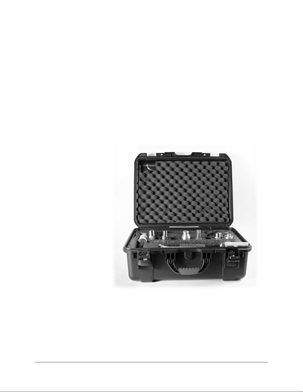
2.2 S250 Tool Kit
The S250 Tool Kit contains the full line of tools required to
service all S250 rockdrill configurations. Using Boart Longyear-
supplied equipment is essential in order to limit the potential to
damage drill parts while improving service shop efficiency.
Please see the following page for parts list and descriptions.
Figure 3: S250 Tool Kit –Part No. 5607146
S250 ROCKDRILL | PARTS & SERVICE MANUAL January, 2021
16
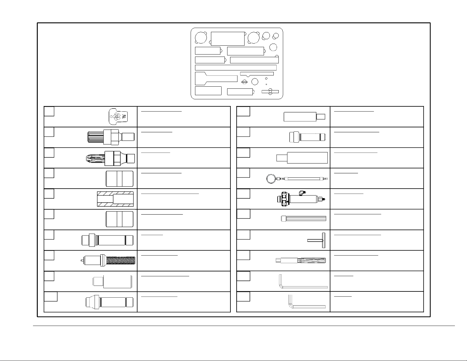
S250 Rockdrill Repair Kit
CHUCK INSERT WEAR GAUGE
Place in chuck insertacross flats.
If top of insert is more than halfway up gauge,
insert should be changed.
CHUCK NUT REMOVER
Insert into Chuck Nut.
Remove with 1/2-inchsocket wrench.
RIFLE NUT REMOVER
Insert into Rifle Nut.
Remove with 1/2-inchsocket wrench.
STOPER CYLINDER MANDREL
Removes small dents from stoper leg
CHUCK INSERT REMOVAL SUPPORT TOOL
Used to remove collaredand collarless chuck insert.
Place chuck in support tool and use 5600114 chuckinsertextractor
with hydraulic press toremove.
JACKLEG CYLINDER MANDREL
Removes small dents from airleg
STOPER PUNCH
Removes stoper handle bushing from cylinder
PISTON EXTRACTOR TOOL
Removes piston and valve chest from cylinder.
Remove front head and chuck, insertpunch into pistonand hammer
out.
VALVE CHEST DISASSEMBLY TOOL
Disassembles valve chest.
Insert punch into top of valve box and hammer out.
LUG BUSHING DRIFT TOOL
Installs cylinder lug bushing on jackleg
CHUCK INSERT PUNCH TOOL
Inserts collared steelchuck insert.
Place chuck insertin chuck insert removalsupport tool5600101,
insert punch in chuck, and press with hydraulic press.
CYLINDER BUSHING EXTRACTOR
Removes brass bushing from inside cylinder and removes bushing
from stoper leg
VALVE CHEST ASSEMBLY TOOL
Used to assemble valve chestand install valve chestin cylinder
AIR HOSE GAUGE
Used to measure airleg pressure.
Attach to airgauge adaptor 5600113.
AIR GAUGE ADAPTOR
Used to measure airleg pressure.
Attach to jackleg clevis body
CHUCK INSERT EXTRACTOR TOOL
Used on collaredsteelchuck.
Place chuck in chuck insert support tool 5600101and press chuck
insert out withhydraulic press.
RETRACT VALVE ASSEMBLY TOOL
Place retractvalve inhandle and gently hammer in with retractvalve
tool
RETRACT VALVE HAND REAMER
Used to remove burrs from retract valve bore
3/16” HEX KEY
3/8” HEX KEY
5600005
5600043
5600044
5600100
5600101
5600102
5600103
5600105
5600106
5600107
5600108
5600110
5600111
5600112
5600113
5600114
5600115
5600116
5600117
5600118
ADDITIONAL TOOLS REQUIRED:
• SOCKETS: 15/16”, 1 1/16”, 1 7/16”, AND 1 1/2”
• 15” CRESCENT WRENCH
•TORQUE WRENCH
• MECHANIC’S HAMMER
1
2
3
456
7
8
9
10
11
12
13
14
15
16
17
18
19
20
1
2
3
4
5
6
7
8
9
10
11
12
13
14
15
16
17
18
19
20

S250 ROCKDRILL | PARTS & SERVICE MANUAL January, 2021
17
2.3 General Maintenance Overview
The maintenance routine of any rockdrill machine always follows
the same set pattern: external clean, strip down, clean parts,
inspect, replace, rebuild, and test. Sophisticated measuring
equipment used to accurately gauge the wear on components is
often not available. Consequently, wear is gauged by simple,
but effective workshop practices.
The jackleg rockdrill is similar in many respects to the stoper.
The stoper maintenance is referred to in Chapter 4.
NOTE: After the unit is completely disassembled, all
components should be cleaned prior to inspection.

S250 ROCKDRILL | PARTS & SERVICE MANUAL January, 2021
18
Chapter 3:
S250 Jackleg/Sinker Drill Maintenance
3.1 Disassembly Procedures
Before any disassembly procedure, ensure that the air and
water hoses are disconnected from the drill
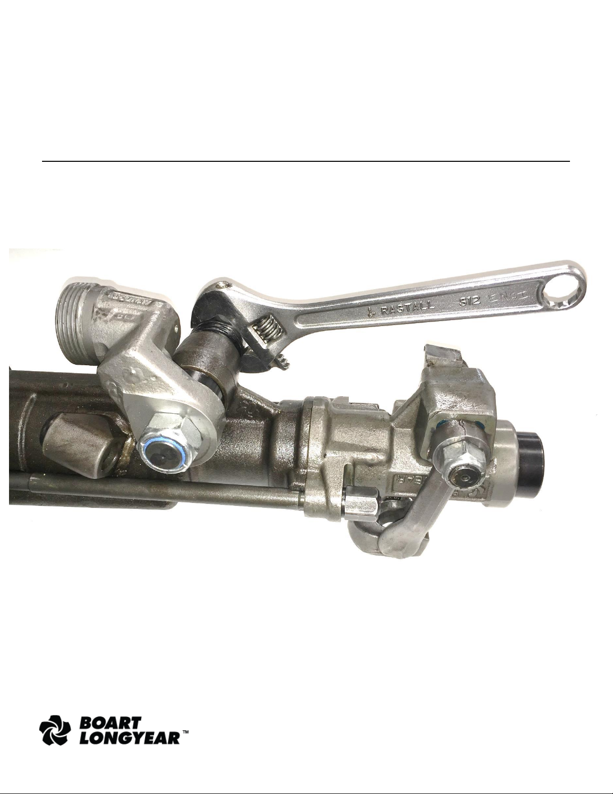
3.1.1 Clevis Body
1. Place the machine upside down on a work bench with the
steel retainer in the position shown.
2. Using an adjustable wrench, unscrew the spindle nut. If the
nut is tight, compress the clevis body spindle spring by
inserting a screwdriver between the spindle lock washer and
the spindle nut.

S250 ROCKDRILL | PARTS & SERVICE MANUAL January, 2021
19
3. Remove the spindle nut, spring, lock washer, and thrust
washer. Remove the keys from the stem end of the spindle.
4. Strike the end of the spindle with a copper mallet or punch and
withdraw the spindle complete with the clevis body from the
cylinder lug bushing.
Table of contents
Other Boart Longyear Drill manuals


