Bob's Space Racers BSR-3000 User manual

Bob’s Space Racers® Inc. ©2017
Table of Contents
1.1
Setting up a Master Board. …………………………….
Page 2
2.1
Setting up a Unit Board ………………………………..
Page 4
3.1
Factory Reset …………………………………………..
Page 7
For Technical Support Contact:
Phone: 1-(386) 677-0761
Opened: Monday –Friday
Office Hours: 8:30AM –5:00PM EST
For after-hours support, charges may apply.
Bob’s Space Racers® Inc. © 2017
427 15th Street,
Daytona Beach, Florida 32117
Phone - (386) 677-0761
Fax - (386) 677-0794
E-mail: tech@bobsspaceracers.com
BSR-3000
Board Setup

Bob’s Space Racers® Inc. ©2017 P a g e | 2
GAME POWER MUST BE ON TO PERFORM THIS OPERATION.
Please Note: Read all the instructions before performing any procedures.
1.1 Setting up a Master Board
The only reason to setup a Master board is because the current Master board has a problem and
the only board available is the Spare or Unit board.
1.1.1 Setting a Unit board as a Master, first perform a Factory Reset.
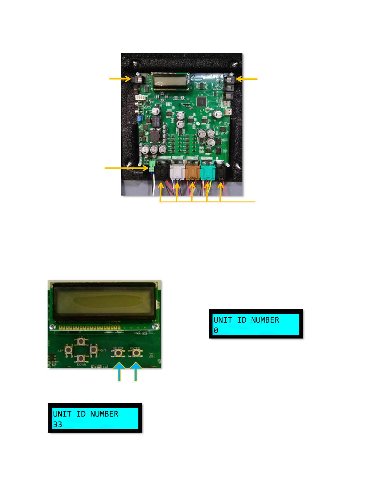
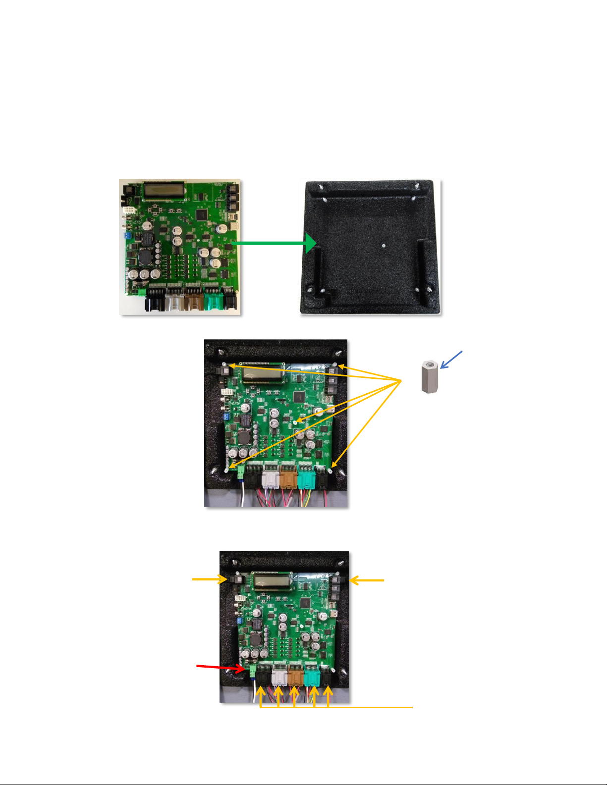
1.1.2 To Factory Reset a 3000 board, first install the board into the board housing and plug all the
cables into the board except the power connector.
1.1.3 Press and hold Enter (Figure 1.1) while plugging in the power connector as seen in Figure 1.2.
Please Note: The screen will turn Red and display the program of the game, example: WTR3K.V20, see Figure 1.3.
1.1.4 The Unit’s Display will flash Red and White. This indicates the board is reset.
1.1.5 The display will now show the program name WTR3K.V20 at the top and Comm Error below it,
see Figure 1.4.
1.1.6 Release the Enter button. The board is now factory reset
1.1.7 Setting the board as a Master is created by entering programming mode on the board designated
to be the Master.
1.1.8 Enter programming mode by pressing and holding Select and Enter on the Master board. See
figure Figure 1.5. until Figure 1.6 is visible. Please Note: This should be about 5 seconds.
1.1.9 Release the two buttons.
1.1.10 The 3000 board is now set as the Master.
Please Note: There is a safety protocol. Two minutes after entering into program mode it will exit automatically. If it exits
before accomplishing the procedure the master saves the last entry. Simply re-access program mode and continue where it
timed out.
Figure 1.6
Figure 1.5
Select
Enter
Figure 1.1
Figure 1.4
Enter
Power
Connector
Figure 1.2
Figure 1.3

Bob’s Space Racers® Inc. ©2017 P a g e | 3
1.1.11 The Master board now needs to have the default values of the options set.
1.1.12 The option sheet sticker (Figure 1.8) is located on the Master’s plex cover.
1.1.13 Set the Default option’s values. Figure 1.8 illistrates that the default colomn is the third
colomn from the right.
Please Note: There is a safety protocol. Two minutes after entering into program mode it will exit automatically. If it exits
before accomplishing the procedure the master saves the last entry. Simply re-access program mode and continue where it
timed out.
1.1.14 Press Select to exit programming mode.
1.1.15 The game will then perform a self-test and return to stand-by mode. If done properly, the
Master LCD should look like Figure 1.9.
1.1.16 The game is ready for normal operation.
Figure 1.9
Figure 1.8
Default
Sample Option Sheet

Bob’s Space Racers® Inc. ©2017 P a g e | 4
2.1 Setting up a Unit Board (BSR Part#: EM080318)
The purpose of setting up a Unit board would be, because the Unit board in the game is no
longer working and needs to be replaced.
2.1.1 When ordering a spare, the Tech Department will need to know the Program of your game. It
is located on the Master Board Plex Cover. See Figure 2.1 as an illustration.
2.1.2Take the Spare or newly purchased board (Figure 2.2) and install the board into the board
housing (Figure 2.3).
2.1.3 Secure the BSR-3000 board with the 3/8-inch Nylon Hex Standoff (Part No.: H0800029) (Figure
2.5) from the old board.
Program: WTR3K.V20
Figure 2.1
Figure 2.4
Figure 2.2
Figure 2.3
Figure 2.5
Sample
3/8-inch Nylon
Hex Standoff

Bob’s Space Racers® Inc. ©2017 P a g e | 5
GAME POWER MUST BE ON TO PERFORM THIS OPERATION.
Please Note: Read all the instructions before performing any procedures.
2.1.4 Plug in all the cables. See Figure 2.6.
2.1.5 Go to the Master board and enter programming mode by mode pressing and holding the Select
and Enter on the Master board (Figure 2.7) until Figure 2.8 is visible. (This should be about 5
seconds).
2.1.6 Release the two buttons
Please Note: There is a safety protocol. Two minutes after entering into program mode it will exit automatically. If it
exits before accomplishing the procedure the master saves the last entry. Simply re-access program mode and continue
where it timed out.
2.1.7 The Spare Unit board’s ID will now show 33 as seen in Figure 2.9.
Figure 2.9
Figure 2.7
Select
Enter
Figure 2.8
Figure 2.6
Network
Cables
Network
Cables
Power
Connector
1. Each connector is keyed.
2. Connections may vary per game.

Bob’s Space Racers® Inc. ©2017 P a g e | 6
2.1.8 Set the Spare Unit board’s ID according to the unit’s location.
2.1.9 Example: If you are replacing Unit #1 Unit Board change the Unit ID to 1, if you are replacing
Unit #2 Unit Board change the Unit ID to 2, and etc.
2.1.10 Press the Right or Left button to change the Unit ID number. See Figure 2.10 and Figure
2.11.
2.1.11 Press the Select button once on the Master board to exit programming mode.
2.1.12 The game will then perform a self-test and return to stand-by mode.
2.1.13 The game is now ready for normal operation
Right
Figure 2.10
Left
Figure 2.11

Bob’s Space Racers® Inc. ©2017 P a g e | 7
GAME POWER MUST BE ON TO PERFORM THIS OPERATION.
Please Note: Read all the instructions before performing any procedures.
3.1 Factory Reset
The reason for a Factory Reset is if the Master is no longer functioning and you are needing to
turn a known working Unit board into a Master or change a Master board into a Unit board.
3.1.1Take the Master or Unit board (Figure 3.1) and install the board into the board housing (Figure
3.2).
3.1.2 Secure the BSR-3000 board with the 3/8-inch Nylon Hex Standoff (Figure 3.4) from the old board.
3.1.3 Plug all the cables into the board except the power connector. See Figure 3.5.
Figure 3.3
Figure 3.1
Figure 3.2
Figure 3.4
Power
Connector
Figure 3.5
3/8-inch Nylon
Hex Standoff
Network
Cables
Network
Cables
1. Each connector is keyed.
2. Connections may vary per game.

Bob’s Space Racers® Inc. ©2017 P a g e | 8
3.1.4 Press and hold Enter (Figure 3.6).
3.1.5 Plug in the power connector. See Figure 3.7.
3.1.6 Continue holding Enter down through the screen turning Red and not flashing. The display will
show the program of the game. Example: WTR3K.V20 (Figure 3.8).
3.1.7 When the display begins to flash Red and White with the program name WTR3K.V20 at the top
and Comm Error below it. See Figure 3.9.
3.1.8 Release the Enter button.
3.1.9 The board is now factory reset.
Revision
Date of Revision
Description of Revision
Approved by
A
January 30, 2017
1.0
Jack Cook
Figure 3.9
Enter
Power
Connector
Figure 3.7
Figure 3.8
Figure 3.6
Table of contents
Popular Carrier Board manuals by other brands

Terasic
Terasic Apollo Carrier Board user manual

ADLINK Technology
ADLINK Technology Q7-BASE Technical reference

Measurement Computing
Measurement Computing PCI-DUAL-AC5 user guide

mikroElektronika
mikroElektronika Comparator click quick start guide

Connect Tech
Connect Tech Astro Carrier user guide

CAES
CAES GR-VPX-XCKU060 manual