Arbor Technology PBE-1101 User manual

- 1 -
Quick Installation Guide
Version 1.0
If you have any technical diculties, please consult the user’s manual rst at:
ftp://ftp.arbor.com.tw/pub/manual
Please do not hesitate to call or e-mail our customer service when you still can not
nd out the answer.
http://www.arbor.com.tw
E-mail: info@arbor.com.tw
♦ Technical Support
PBE-1101
LAN
1 x LAN port by CPU
module
1 x GbE port
Audio
MIC-in/ Line-in/ Line-
out
VGA
LVDS,
Analog RGB
Form Factor
ETX Carrier Board
I/O
PC104-Plus/ USB/ IDE/
COM/ LPT/ DIO/ CF II/
I2C/ IrDA/ PS/2
Copyright® All Rights Reserved.
4041110100100P
Declaration of Conformity
FCC Class A
This device complies with Part 15 of the FCC Rules. Operation is subject to the
following two conditions : (1) this device may not cause harmful interference, and
(2) this device must accept any interference received, including interference that
may cause undesired operation.
85
85

- 2 -
Ordering Information
Optional Accessories
Before you begin installing your single board, please make sure that the following
materials have been shipped:
Packing List
1 x
PBE-1101 ETX 3.02 Carrier Board
1 x Quick Installation Guide
PBE-1101
ETX 3.02 Carrier Board
CBK-15-1101-00
Cable kit
1 x Audio cable
2 x USB cables
2 x Serial port cables
1 x IDE cable
1 x LPT cable
2 x Ethernet cables
1 x VGA cable
1 x KB/MS cable
2 x SATA cables
1 x Power cable (4 wires)
1 x Power cable (2 wires)

- 3 -
Specifications
I/O
Serial Port 3 x RS-232 port with pin-header
1 x RS-232/422/485 selectable port with pin-header
Parallel Port 1 x LPT port
Keyboard & Mouse 1 x box header (PS/2 interface for keyboard and mouse)
USB 2.0
4 x USB 2.0 port w/ pin header
Expansion
PC/104-Plus interface
1 x I2C
Storage
1 x IDE box header
1 x CompactFlash Type II socket
Ethernet
1 x LAN port by CPU module
1 x GbE port
Digital I/O
16-bit Digital Input/Output, 8-in/ 8-out
Audio
Mic-in/Line-in/Line-out
RF
1 x IrDA
Display
Graphic Interface
1 x VGA port
1 x Dual channels 24-bit LVDS port
OS Support
Depends on CPU module
Mechanical & Environmental
Power Requirement +12V DC input
Power Consumption 1.789A@5V with EmETX-i2304-E3825
2.025A@5V with EmETX-i2304-E3845
Operating Temp. -40 ~ 85ºC (-40 ~ 185ºF)
Operating Humidity 10 ~ 95% @ 85ºC (non-condensing)
Dimensions (L x W) 114 x 95mm(4.48” x 3.7”)

- 4 -
Block Diagram
COM3, 4 1 x USB 2.0 port
COMB
2x10 BH
USB to UART
FT2232
IDE ATA I/F
IDE1
2x22 BH
CFD1
CF socket
ISA Bus
CONA1
PC/104 slot
I2C I/F
I2C1
1x5 PH
Analog R.G.B. VGA1
2x8 BH
LVDS LVDS1
2x15 BH
COM1, 2 COMA
2x10 BH
KB, MS KBM1
1x6 BH
LPT LPT1
2x13 BH
IrDA IR1
1x5 PH
GbE LAN 2nd LAN
AX88179
LAN2
2x5 PH
USB1, 2
2x5 PH
1 x USB 2.0 port
AUDIO1
2x5 BH
MIC-in/ Line-in/ Line-out
PC104+
PCI/104 slot
PCI I/F
3 x USB 2.0 ports 1 x USB 2.0 port
1 x USB 2.0 port
Connector ETX3
Connector ETX2 Connector ETX1
Connector ETX4
LAN1
2x5 PH
10/100 LAN
PBE-1101 ETX Carrier Board
USB Hub
GL852G

- 5 -
Board Dimensions

- 6 -
Connectors Quick Reference
3
50
1
2526
+
21
910
21
9 10
2
9
10 2
1
9
10
10
91
2
1
20
19
1 2
2019
1 2
A1
B1
A32
B32
D19
C19
D0
C0
1
2
20
19
1
44
43
2
1
1
1
1
1
1
2
9 10
1
2
1
1
1
4
3
21
1 14
13 26
2
30
29 1
D1
C1
B1
A1
D30C30B30A30
6
1
S
1
1
8
5
1
16
15
12
12VGND
DIO1
1
AUDIO1
2
USB2
3
USB1
4
VGA1
5
COMB
6
COMA
7
LPT1
8
KBM1
9
FAN2
10
PWR1
12
JFRT1
14
TV1
11
JCOM1
13
LVDS1
15
INV1
16
IR1 17
JBAT1 26
JVLCD1 24
JBLON1 27
PC104+ 31
FAN1 30
JCFD1 29
CFD1 28
JRS2 23
IDE1 18
CONA1 19
LAN2 21
LAN1 22
LANLED 20
JWT1 25

- 7 -
JumpersJumpers
ConnectorsConnectors
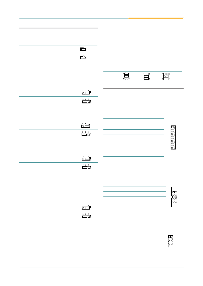
JBAT1: Clear CMOS Setting (26)
Connector type: 2.00mm pitch 1x3-pin headers.
Pin Mode
1-2 Keep CMOS (Default)
23 1
2-3 Clear CMOS
23 1
JRS2: COM2 RS-232/422/485 Selection (23)
It can be congured COM2 to operate in RS-232, RS-
422 or RS-485 mode.
Connector type: 2.00mm pitch 2x3-pin headers.
Mode RS-232
(Default) RS-422 RS-485
1-2 ON OFF OFF
3-4 ON ON OFF
5-6 OFF ON ON
6
5
2
1
6
5
2
1
6
5
2
1
JVLCD1: LCD Panel Voltage Selection (24)
The voltage of LCD panel could be selected by
JVLCD1 in +5V or +3.3V.
Connector type: 2.00mm pitch 1x3-pin headers.
Pin Voltage
1-2 +5V
23 1
2-3 +3.3V (Default)
23 1
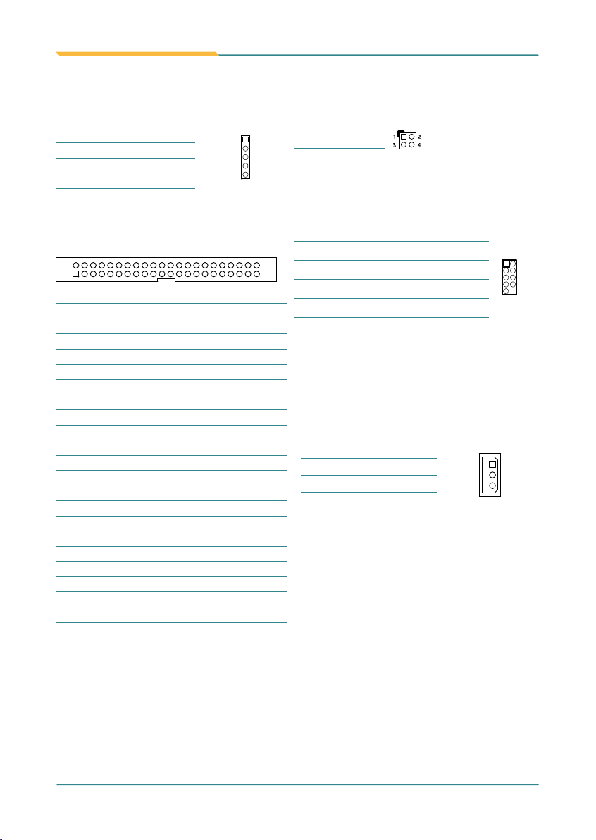
DIO1: Digital I/O Connector (1)
DIO1 supports 8-bit In/ 8-bit Out.
Connector type: 2.00mm pitch 2x10-pin headers
Pin Description Pin Description
12
2019
1DO0 2 DO1
3DO2 4DO3
5 DO4 6DO5
7DO6 8DO7
9 GND 10 GND
11 DI0 12 DI1
13 DI2 14 DI3
15 DI4 16 DI5
17 DI6 18 DI7
19 +5V 20 +12V
AUDIO1: AC97 Connector (2)
Connector type: 2.00mm pitch 2x5 box headers.
Pin Desc. Pin Desc.
1 2
9 10
1 Line_In_Left 2 Line_In_Right
3 GND 4 GND
5 MIC 6N/C
7 GND 8 GND
9Speaker Left 10 Speaker Right
USB1 ~ 2: USB Connectors (4, 3)
Connector type: 2.00mm pitch 2x5-pin headers.
Pin Desc. Pin Desc.
1
9
2
10
1+5V 2 +5V
3USBD- 4USBD-
5 USBD+ 6USBD+
7 GND 8 GND
9 GND 10 N/C (Key)
JCFD1: CF IDE1 mode Selection (29)
Connector type: 2.00mm pitch 1x2-pin headers.
Pin Mode
Short Master 1 2
Open Slave (Default)
1 2
JWT1: WDT Mode Setting (25)
Connector type: 2.00mm pitch 1x3-pin headers.
Pin Mode
1-2 NMI
23 1
2-3 RST_SW (Default)
23 1
None Disable WatchDog Timer
JBLON1: LCD Backlight Selection (27)
The LCD panel backlight active mode could be
selected by JBLON1 in High or Low.
Connector type: 2.00mm pitch 1x3-pin headers.
Pin Mode
1-2 Active High (Default)
23 1
2-3 Active Low
23 1

- 8 -
LPT1: Parallel Port Connector (8)
Connector type: 2.00mm pitch 2x13-pin box headers.
Pin Description Pin Description
1
13
14
26
1STROBE# 14 AFD#
2PTD0 15 Error#
3 PTD1 16 INIT#
4PTD2 17 SLIN#
5PTD3 18 GND
6 PTD4 19 GND
7PTD5 20 GND
8 PTD6 21 GND
9 PTD7 22 GND
10 ACK# 23 GND
11 Busy 24 GND
12 PE 25 GND
13 Select 26 N/C
COM A~B: RS-232 Connectors (6, 7)
Connector type: 2.00mm pitch 2x10-pin box headers.
Pin Description Pin Description
12
2019
1DCD#1 / 3 2 RXD1 / 3
3TXD1 / 3 4DTR#1 / 3
5GND 6 DSR#1 / 3
7RTS#1 / 3 8CTS#1 / 3
9RI#1 / 3 10 N/C
11 DCD#2/ 4 12 RXD2/ 4
13 TXD2/ 4 14 DTR#2/ 4
15 GND 16 DSR#2/ 4
17 RTS#2/ 4 18 CTS#2/ 4
19 RI#2/ 4 20 N/C
KBM1: Keyboard & Mouse Connector (9)
Connector type: 2.0mm pitch 1x6-pin box wafer
connector.
Pin Description
1 KB_DATA
2GND
3MS_DATA
4 KB_CLK
5KB_VCC
6MS_CLK
FAN2: Fan Power Connector (10)
FAN2 is a 3-pin headers for the fan. The fan must be
a +12V fan.
Pin Description
1
2
3
1 GND
2 +12V
3N/C
VGA1: Analog RGB Connector (5)
Connector type: 2.00mm pitch 2x8-pin box headers.
Pin Description Pin Description
12
16
15
1 RED 2GREEN
3BLUE 4N/C
5GND 6 GND
7 GND 8 GND
9N/C 10 GND
11 N/C 12 VDDAT
13 HSYNC 14 VSYNC
15 VDCLK 16 N/C
TV1: TV-out Connector (11)
Connector type: 2.00mm pitch 1x6-pin box wafer
connector
Composite Video
1CVBS 2GND
3Unused 4GND
5Unused 6GND
S-Video
1Unused 2GND
3Luminance 4GND
5Chrominance 6GND

- 9 -
JCOM1: RS-422/485 Connector (13)
Connector type: 2.00mm pitch 1x4 box wafer
connector.
Pin RS-422 RS-485
1
2
3
4
1 TX+ DATA+
2TX- DATA-
3 RX+ N/C
4 RX- N/C
PWR1: Power Supply Connector (12)
Connector type: Terminal blocks.
Pin Description
1
2
3
4
5
6
1+12V
2GND
3 GND
4 GND
5 +5V
6+5V
JFRT1: Switches and Indicators (14)
It provides connectors for system indicators that
provides light indication of the computer activities
and switches to change the computer status.
Connector type: 2.00mm pitch 2x5-pin headers.
Pin Description Pin Description
10
9
1 2
1RESET+ 2 GND
3POWER_LED+ 4POWER_LED-
5 HDD_LED+ 6HDD_LED-
7SPEAKER+ 8SPEAKER-
9 None 10 GND
Pin Desc. Pin Desc.
1
2930
2
2VDD 1 VDD
4TX2CLK+ 3 TX1CLK+
6TX2CLK- 5 TX1CLK-
8 GND 7 GND
10 TX2D0+ 9 TX1D0+
12 TX2D0- 11 TX1D0-
14 GND 13 GND
16 TX2D1+ 15 TX1D1+
18 TX2D1- 17 TX1D1-
20 GND 19 GND
22 TX2D2+ 21 TX1D2+
24 TX2D2- 23 TX1D2-
26 GND 25 GND
28 TX2D3+ 27 TX1D3+
30 TX2D3- 29 TX1D3-
LVDS1: LVDS LCD Connector (15)
The LVDS connector on board 30-pin headers and
supports 18/36-bit
INV1: LCD Inverter Connector (16)
Connector type: 2.00mm pitch 1x5-pin box wafer
connector.
Pin Description
1
2
3
4
5
1+12V
2GND
3Backlight on/o
4Brightness control
5GND

- 10 -
IDE1: Primary IDE Connector (18)
Connector type: 2.00mm pitch 2x22-pin box headers
1 2
43 44
Pin Description Pin Description
1RESET# 2 GND
3DATA7 4DATA8
5DATA6 6DATA9
7DATA5 8 DATA10
9DATA4 10 DATA11
11 DATA3 12 DATA12
13 DATA2 14 DATA13
15 DATA1 16 DATA14
17 DATA0 18 DATA15
19 GND 20 N/C
21 DREQ 22 GND
23 IOW# 24 GND
25 IOR# 26 GND
27 IRDY 28 IDSEL
29 ACK# 30 GND
31 IRQ 32 N/C
33 AD1 34 ATA66 DETECT
35 AD0 36 AD2
37 CS#2 38 CS#3
39 ACT# 40 GND
41 +5V 42 +5V
43 GND 44 GND
LANLED: LAN LED Indicators (20)
Connector type: 2.54mm pitch 2x2-pin headers
Pin Description
2
1
4
3
1-2 -ACTLED
3-4 -LILED
CONA1: PC/104 ISA bus Slot (19)
LAN1~2: Ethernet Connectors (21, 22)
Connector type: 2.00mm pitch 2x5-pin headers
Pin Desc. Pin Desc.
1
9
2
10
1TX_MDI0+ 2TX_MDI0-
3RX_MDI1+ 4MDI2+
5MDI2- 6RX_MDI1-
7MDI3+ 8MDI3-
9N/C 10 N/C (Key)
IR1: Infrared Connector (17)
Connector type: 2.54mm pitch 1x5-pin headers.
Pin Description
1
2
3
4
5
1+5V
2 N/C
3 IRRX
4 GND
5IRTX
CFD1 : Compact Flash Disk socket
(share with IDE1) (28)
FAN1: System Fan Power Connector (30)
FAN1 is a 3-pin headers for the CPU fan. The fan
must be a +5V fan.
Pin Description
1
2
3
1N/C
2 +5V
3 GND
PC104+: PC/104+ PCI Bus Expansion
Slot (31)
Table of contents
Other Arbor Technology Carrier Board manuals