bocci 16.40 User manual

© 2016, Bocci Design and Manufacturing Inc. All rights reserved. Any inquiries should be directed to: info@bocci.ca.
sales@bocci.ca
www.bocci.ca
europe@bocci.ca
www.bocci.ca
US patent # D754,911
EU patent #002672774 - 0001 to 0012
Made in Vancouver, Canada
16.40
203 (8”)
216 (8.5”)
64 (2.5”)
forty
PENDANTS:
250mm (10”) diameter base plate
MOUNTING:
The 16.40 is a tree-like 16 installation using 40 pendants and a modular
stainless steel armature system mounted to a seven tube stainless steel ‘birch’
base. These trees are designed to be grouped into forest-like assemblies of a
variety of different sizes and types, but are strong compositional elements on
their own. Installation of these trees is involved and Bocci recommends a
structural consultant to assess the viability of the system in the context
in which it is to be installed. Installation requires anchoring into either an
existing structural slab, or a newly built foundation, to the specifications of
the design drawings including appropriate drainage if exposed to water and
remotely mounted LED drivers.
16 is formed by sequentially pouring three separate layers of coloured, molten
glass – in varying opacities – on a horizontal plane. Each layer responds to the
indeterminate shape of the previous pour to create a uniquely layered whole. Two
of these pieces are then attached and illuminated with an internal LED lamp.
The finished 16 is visually complex: each separate colour layer is visible through
the other layers, with light reflecting along the edges.
Each armature segment carries low-voltage electricity and diverges into 2-4
separate branches, allowing both vertical and horizontal deployment with an
infinite variety of possible forms. The branches simply click together during
installation for custom, on-site arrangements.
All trees are rated for outdoor (or indoor) use based on structural analysis for
the maximum loaded trees noted above in moderately sheltered locations near
seawater with minimal snow loads. Any other application restraints may need
further engineering.
The distance of a pendant from the tree can only be increased if fewer pendants
per branch are used, up to a maximum of 1800mm with a single pendant.
+
NOTES
DESCRIPTION
LAMPING: 1.8w LED (72w total draw)
poured glass, electrical components, bead blasted base plate,
bead blasted stainless steel armature components
MATERIALS:
approximately 297kg (655lb)
WEIGHT:
remote
TRANSFORMERS:
Purchase replacement lamps online at www.bocci.ca/lamps
Unless otherwise specified, a single class 2 transformer will be sent with
every 13 pendants.
Available in a wet location configuration.
+
+
Note: transformers must be mounted remotely in an easily accessible and
hidden location for ease of long-term maintenance.
+
7100
(280”)
1950
(77”)
250 (10”)
2800 (110”)
Design by Omer Arbel
PRODUCT SPECIFICATION

INSTALLATION INSTRUCTIONS
1
Installation of these trees is involved and Bocci recommends a structural consultant to assess the suitability & implications
of the environment it is to be installed in, in relation to climatic based forces to which it was designed. Installation requires
anchoring into either an existing structural slab, or a newly built foundation, to the specifications of the design drawings
including appropriate drainage if exposed to water and remotely mounted LED drivers.
Anchoring of these trees is critical and it is imperitive that the assembly drawings are followed. However the foundation and
fixing of anchors to the foundation are the responsibility of the client. Drawings are provided only to provide a general idea
of what is involved in installation for early design phase development. The trees are design for the load assumptions above
and thus should not be installed in a location where any of the above design forces are to be surpassed. Neglecting the
design forces may lead to failure of the structure. Where installation sites have climatic data providing forces less than those
mentioned above, the design of a suitable foundation is to be provided by aforementioned structural engineer.
The modular trees will deflect under wind loading. All modular tree components should be kept at least 600mm away from
any other object, so as to allow space for the tree to deflect without coming into contact with other objects and causing
damage to the object.
For our purposes, and due to specific site constraints that will guide the preparation of the site, the installation instructions
begin with the anchors already installed.
© 2016, Bocci Design and Manufacturing Inc. All rights reserved. Any inquiries should be directed to: info@bocci.ca.
16.40
270mm diameter stainless steel
cover plate
250
250mm diameter x 19mm thick
304 Stainless steel base plate
Line of water
drainage
and wire
tray below
76
50mm diameter hole in base
plate for wiring and drainage
centered under tubes.
4 - 6mm thick
gusset plates
180
DL: 23N (5.3lbs)PENDANTS:
21 m/s
6 N /pendant
MAX UNFACTORED WIND SPEED:
MAX UNFACTORED SNOW / ICE LOAD:
UNFACTORED SEISMIC LOAD: 1215N HORZONTAL @ 4700mm ABOVE BASE CONNECTION
Mf: 6 kN*m Vf: 1 kN
FACTORED DESIGN LOAD FOR BASE CONNECTION:
LOAD SUMMARY &
DESIGN CRITERIA
Cast-in anchors (shown above)
4 - 19mm anchor bolts
with nut and washer at the ends
Post-installed anchors
4 - 19mm A325 threaded rods
Drill and epoxied with Hilti RE-500
into existing structural slab
min. 19mm
Finish floor height
aligns with top of
cap with 3mm
reveal around
Rebar
Concrete
Structural anchors
Double nut for levelling
Non-shrink grout
Stainless steel
cover plate
145mm
Ensure space left
for cables
Plate sloped to provide
water drainage
The foundation
drawings are meant
only to provide a
general idea of
what is involved in
installation and a
structural engineer
must specify a
suitable foundation
using the load
summary and design
criteria provided
above.
INSTALLATION INSTRUCTIONS
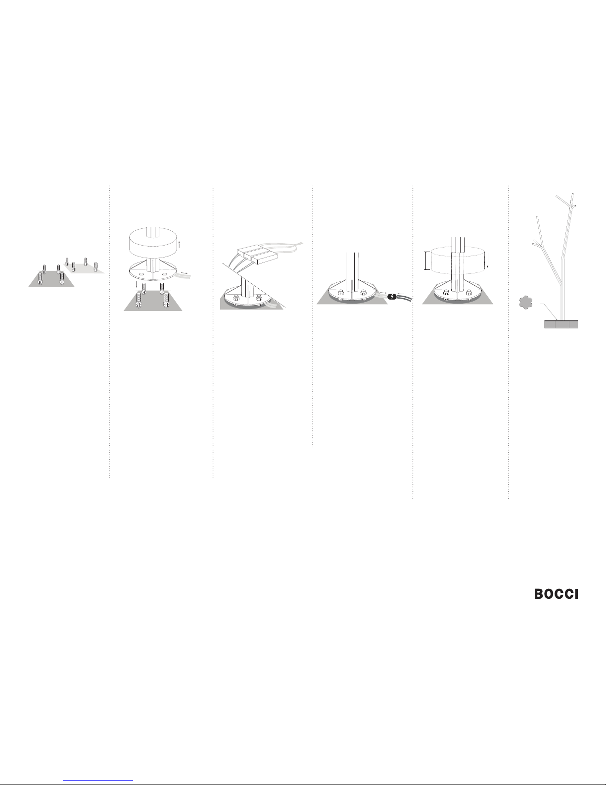
21 3 4 5 6
Using heavy equipment, orient the
tree base in the direction you want the
branches to go, and lower it onto the
anchor bolts. Repeat this step for all
nearby trees.
Once all tree bases are in place, level
the bases using the nuts below the
baseplates. Place another washer on
each anchor followed by a nut and
tighten the nuts on top until snug.
Note:
There will be a wire coming from the
middle of the bottom of each base,
make sure that the wires do not get
damaged during install.
With the anchors in place, spin
two of the provided nuts followed
by a washer onto each anchor.
Make sure a minimum of 19mm
(3/4”) space for drainage below
the tree is maintained.
Mount LED drivers remotely and route
output wiring from LED driver to tree
location using 12GA direct burial wire.
Note: Up to 13 pendants may be
connected to a single driver.
Note:
Drivers must be remote mounted in a
close by, waterproof, accessible and
hidden location for ease of long term
maintenance. Installation to be done
by certifi ed personnel to ensure code
compliance.
Connect the cables to the open slots
in the terminal block on the 12V side
of the LED drivers. Ensure that the
braided outer wires are all connected
to one 12V output wire and all inner
insulated wires are connected to the
other or a short will occur.
Once all the coaxial connections are
made, connect the line voltage to the
open slot in the appropriate terminal
block.
Once all wiring connections are
complete, and the nuts are snug-
tight, slide the cover down over
the plate until it rests on either the
gussets or the ground.
Note:
Bocci recommends installing the
fi nish fl oor height higher than the
cover plate with a small reveal
around the tree base or alternately
installing fl ush with the cover plate.
Depending on the fi nal installation
fi nish, you may want to fi nish the
fl oor at this point if the fi nished
fl oor can support a lift or scaffold
for installation of pendants. If not,
complete the installation following
steps 7 - 11 before completing the
fl ush mount detail.
You should now have an
upright tree base ready
for composition of the
pendants according to the
specifi cation sheet.
© 2016, Bocci Design and Manufacturing Inc. All rights reserved. Any inquiries should be directed to: info@bocci.ca.
120V or 240V line
12V output
16.40
145mm (5.7”)
12V output
fl ush mount
detail diagram

INSTALLATION INSTRUCTIONS © 2016, Bocci Design and Manufacturing Inc. All rights reserved. Any inquiries should be directed to: info@bocci.ca.
910 11
8
All exposed male connecting pieces will
terminate with pendants, keep this in
mind as you compose your light fi xture.
Installation strategy involves connecting
a combination of straight female
connector pieces and bent or branch
male components.
Take your time to compose and
recompose your light installation to
your chosen aesthetic (see bocci.ca for
examples).
Note:
The components are sorted into kits by
branch and these kits can be arranged
in any confi guration desired. However, if
components are swapped between kits
or different groupings are used on other
branches, it may be possible to overload
a branch leading to pieces bending.
It is easier to assemble branches in
smaller sections before attaching to the
tree bases.
Each armature component can be
rotated in 45 degree intervals. Once the
component orientation is chosen, set
in place using the set screws provided
with a slotted screw driver. Each piece
of tubing has 2 - 3 set screws around
its circumference. These should be
tightened evenly so that all set screws
are engaged the same amount,
centering the male end within the
female connection.
Note:
The size of the armature tubing
corresponds to specifi c set screw sizes:
small Ø17mm - M4
medium Ø 20mm - M5
large Ø 25mm - M6
Insert LED into lampholder, and then
plug each lampholder into all exposed
male connections.
Slide the pendant onto the male
connector, orient as desired, and secure
using an M3 set screw (provided).
Note:
If the fi xture sags or seems unbalanced
you may be overloading the fi xture.
Remove pendants, or shorten cantilever
as required.
Tighten all set screws to 0.5 Nm (0.36
ft/lb) and clean fi ngerprints from
pendants.
Turn light fi xture on.
*
exposed male ends
Components are sorted into kits to correspond
to specifi c branches to aid in installation. Do
not mix or combine kits as the engineering
and design criteria have been done for these
specifi c confi gurations.
Take inventory of all the parts in the kit as you
will use these to compose your fi xture.
There may be ten types of components and
up to three sizes of each piece (Ø17mm,
Ø20mm, Ø25mm) depending on the fi xture
ordered.
You may use all the components, or any
combination of them in your composition.
Note the connectors on each end are either
male (m) or female (f). A male part can only be
joined with a female part.
7
a
c
b
d
e
g
f
h
i
j
a. 150mm connector (f)
b. 250mm connector (f)
c. 510mm connector (f)
d. reducer (f)
e. u turn (m)
f. elbow (m)
g. bend (m)
h. extender (m)
i. double split (m)
j. split (m)
16.40
Other bocci Light Fixture manuals

Popular Light Fixture manuals by other brands


Cooper Lighting
Cooper Lighting Metalux WE Series Specifications

IKEA
IKEA RUNNEN manual

Cooper Lighting
Cooper Lighting METALUX G SERIES Specification sheet

Home Accents Holiday
Home Accents Holiday 22RT13722111 Assembly instructions

Lightolier
Lightolier Lytespan 8420 specification

Light Sky
Light Sky PL61W3 user manual

Chamberlain
Chamberlain Secure Home SH-9132AU Installation and operating instructions

Martin
Martin MAC Encore Performance Service manual

Audibax
Audibax Monster Beam 7R user manual

Lightolier
Lightolier Lytecel 6 LIA6GPNXR154 specification

Chroma
Chroma Studio Force D Compact quick start guide

Ledj
Ledj Rapid QB1 user manual