Bock Water heaters ODOT200 Series Service manual

WARNING
Improper installation, adjustment, alteration,
service or maintenance can cause serious injury
or property damage. Refer to this manual. For
assistance or additional information, consult a
qualified installer or service agency.
WARNING
Install in accordance with all local codes. In the
absence of local codes, refer to NFPA 54
CAUTION
The recommended temperature for normal
residential use is 120°F. The dial on the aquastat
does not always reflect the out-coming water
temperature and it could occasionally exceed
120°F. Variation in out-coming temperature could
be based on factors including but not limited to
usage patterns and type of installation. Test water
at the tap nearest to the water heater. See page 37
for measuring the out-coming water temperature.
WARNING
Hotter water increases the risk of scald injury.
Before adjusting the water temperature setting,
read this instruction manual. Temperatures at
which injury occurs vary with the person’s age
and the length of exposure. The slower reaction
time of children, elderly or physically or mentally
challenged persons increases the scalding hazard
to them. It is recommended that lower water
temperatures be used where these exposure hazards
exist. Households with small children or invalids
may require a temperature setting less than 120°F
to prevent accidental contact with hot water.
To produce less than 120°F, use point-of-use
temperature limiting devices.
If higher water temperature is needed in part of
the water system, automatic temperature limiting
devices must be used on all lines to water taps.
WARNING
Water heater blankets may restrict air flow to the
water heater and cause fire, asphyxiation, personal
injury or death.
THIS MANUAL HAS BEEN PREPARED TO
ACQUAINT YOU WITH THE INSTALLATION,
OPERATION, AND MAINTENANCE OF YOUR
WATER HEATER AND TO PROVIDE IMPORTANT
SAFETY INFORMATION.
Read all instructions thoroughly before attempting
installation or operation of your water heater. Keep
these instructions for future reference.
Local plumbing and electrical codes must be
followed in the installation of this water heater.
In the absence of a local code use the UNIFORM
PLUMBING CODE and the NFPA Code. Local codes
may supersede instructions in this installation
manual.
These instructions are a guide for the correct
installation of the water heater. The manufacturer
will not be liable for damages caused by failure to
comply with the installation and operating instruc-
tions outlined on the following pages.
FAILURE TO FOLLOW THESE INSTRUCTIONS OR
ALL APPLICABLE BUILDING CODES
AND REGULATIONS VOIDS THE WARRANTY ON
THIS WATER HEATER.
Warranty, Registration Card and Parts List are included.
Owner: Please remember to return the Registration Card!
To the Consumer:
Please read these instructions and keep for future
reference.
To the Installer:
Please read these instructions and deliver to
consumer when installation is complete.
Rev3 2/2021
23447
— Do not store or use gasoline or other flammable
vapors and liquids in the vicintiy of this or any
other appliance.
—WHAT TO DO IFYOU SMELL GAS
- Do not try to light any appliance.
- Do not touch any electrical switch; do not use any
phone in your building.
WARNING: If the information in these instructions is not followed exactly, a
fire or explosion may result causing property damage, personal injury or death.
Installation and Operation Instructions Manual
Models: ODOT200, ODOT250, ODOT299, ODOT300*2, ODOT400*2, ODOT500*2
Outdoor Commercial Gas Water Heater
— Do not store or use gasoline or other
flammable vapors and liquids in the
vicintiy of this or any other appliance.
— WHAT TO DO IF YOU SMELL GAS
• Do not try to light any appliance.
• Do not touch any electrical switch; do
not use any phone in your building.
• Immediately call your gas supplier
from a neighbor’s phone. Follow the
gas supplier’s instructions.
• If you cannot reach your gas supplier,
call the fire department.
— Installation and service must be
perfomred by a qualified installer,
service agency or the gas supplier.

IMPORTANT SAFETY INSTRUCTIONS
The proper installation, use and servicing of this water heater is very
important to your safety and the safety of others.
This is the safety alert symbol. Statements following this symbol contain
important safety information. Obey all safety messages that follow this
symbol to avoid possible injury or death.
Important safety information will be preceded by the safety alert symbol
and the words DANGER, WARNING, CAUTION, OR NOTICE.
DANGER indicates an imminently hazardous situation which, if not
avoided, will result in serious injury or death.
WARNING indicates a potentially hazardous situation which, if not
avoided, could result in serious injury or death.
CAUTION indicates a hazardous situation which, if not avoided, could
result in minor or moderate injury.
NOTICE calls attention to observe a specified procedure.
SAVE THESE INSTRUCTIONS
DANGER
Water heaters utilizing Liquefied Petroleum gas (LP) are different from
natural gas models. A natural gas heater will not function safely on LP gas
and vice versa. To avoid possible equipment damage, personal injury or
fire: DO NOT connect this water heater to a fuel type not in accordance
with the rating label. These units are only certified for a single fuel type.
DANGER
Failure to properly install the vent and combustion air intake system as
outlined in this manual can result in unsafe operation of the water heater.
To avoid the risk of fire, explosion, or asphyxiation from carbon monoxide,
never operate this water heater unless it is properly vented and has
adequate air supply for combustion and dilution of flue gas. Be sure to
inspect the system for proper installation at initial start-up; and at least
annually thereafter. See the Maintenance section for more information.
Page 2

TABLE OF CONTENTS
Section I: Specifications .............................................4
Section II: General Information ........................................5
Section III: Pre-Installation ............................................9
Section IV: Installation ..............................................13
Section V: Operation ...............................................23
Section VI: Maintenance ............................................27
Section VII: Troubleshooting .........................................31
Section VIII: Parts List ...............................................36
Section IX: Warranty ...............................................40
Page 3
Model
Rated Storage Capacity,
GAL (L)
Rated Maximum Input,
Btu/hr (kW)
Thermal Efficiency (%)
@ Max. Input
Recovery @ 100°F
rise, GAL/HR (L/HR)
A
C
E
G
HOT (NPT)
Rated Minimum Input,
Btu/hr (kW)
Thermal Efficiency (%) @
Min. Input
1st Hr. Delivery @
100°F rise, GAL (L)
B
D
F
COLD (NPT)
Gas (NPT)
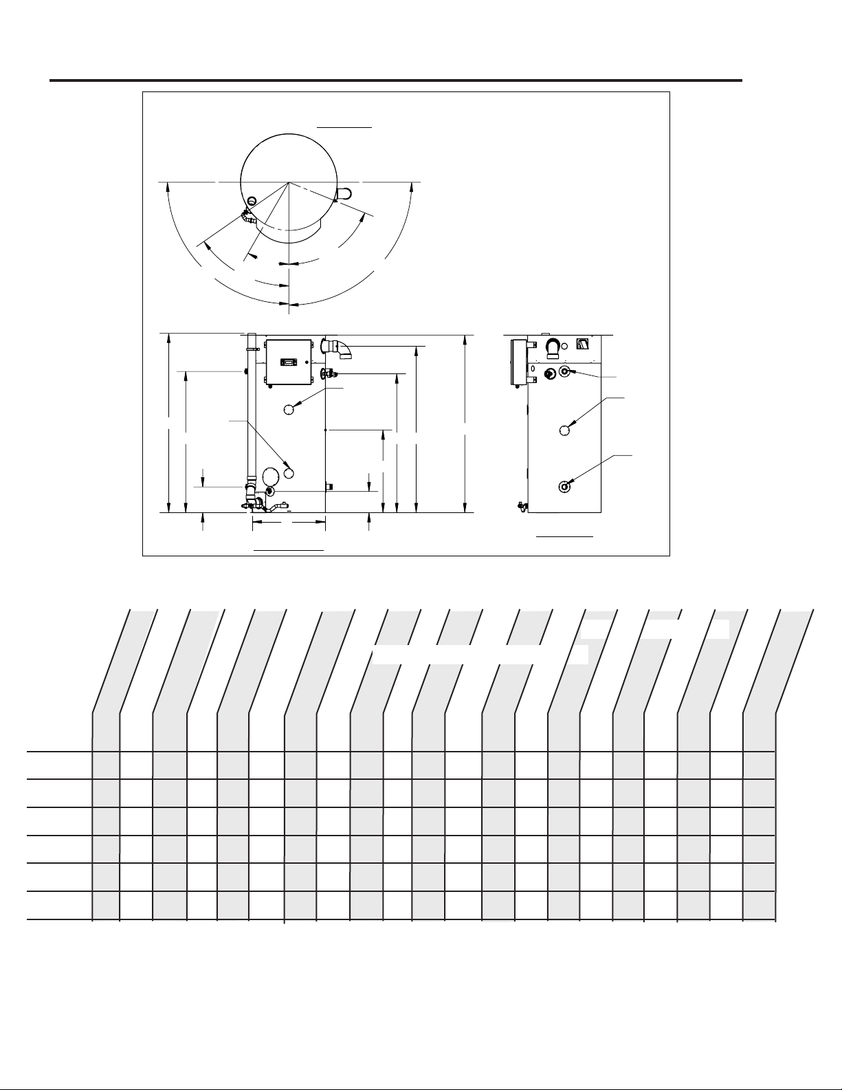
Table 1: Dimensions
Page 4
SECTION I: SPECIFICATIONS
B
H
E
F
A
G
D
I
C
RETURN
COLD
COMBUSTION INTAKE
GAS CONN.
TI Anode
Cover
ASME
Plate
COLD
RETURN
HOT
30° 68°
90° 90°
55°
TOP VIEW
HOT/COLD HOT/COLD
GAS CONN.
DRAIN
T&P VALVE
EXHAUST
DRAIN
FRONT VIEW
SIDE VIEW
Model
Dimensions in Inches (cm)
Cold
NPT
Hot
NPT
Recirc.
Return
NPT
Gas
NPT
Air
Intake
PVC
Exhaust
Vent
PVC
Shipping Weight
LBS (kg)
A
B
C
D
E
F
G
H
I
ODOT300*2 -(A)
78.8
(200)
32.5
(82)
62.75
(159)
11.4
(29)
9.4
(24)
61.7
(156)
74.0
(188)
36.3
(92)
79.66
(202)
2" 2" 1"
1-1/2"
4" 4"
1185 (539)
ODOT400*2 -(A)
78.8
(200)
32.5
(82)
62.75
(159)
11.4
(29)
9.4
(24)
61.7
(156)
74.0
(188)
36.3
(92)
79.66
(202)
2" 2" 1"
1-1/2"
4" 4"
1185 (539)
ODOT500*2 -(A)
78.8
(200)
32.5
(82)
62.75
(159)
11.4
(29)
9.4
(24)
61.7
(156)
74.0
(188)
36.3
(92)
79.66
(202)
2" 2" 1"
1-1/2"
4" 4"
1185 (539)
Figure 1: All Models
DIMENSIONS, INCHES (cm)
NOTE: * denotes fuel type, N or LP, and sux “-A” denotes ASME version.
Replace * in Model with fuel type abbreviation. Natural Gas (N) or Propane Gas (LP).
For HIGH ALTITUDE models, the following additional suxes are dened as:
“-H25” = Approved for altitudes greater than 2,000 up to 5,400 FT
For natural gas: �
MINIMUM GAS SUPPLY PRESSURE (at gas control) = 3.5” W.C. (dynamic)
MAXIMUM GAS SUPPLY PRESSURE (at gas control) = 14” W.C. (static or dynamic)
100 199,999 76,000 95 98 228 298 67.25 32.00 51.53 11.43 9.43 50.18 62.75 69.50 N/A 2” 2” NA 1 1,195
(378) (58.6) (22.3) (863) (1,128) (171) (81) (131) (29) (24) (127) (159) (177) (542)
100 250,000 76,000 94 98 282 352 67.25 32.00 51.53 11.43 9.43 50.18 62.75 69.50 N/A 2” 2” N/A 1” 1,195
(378) (73.3) (22.3) (1,067) (1,332) (171) (81) (131) (29) (24) (127) (159) (177) (542)
100 299,999 76,000 93 98 334 404 67.25 32.00 51.53 11.43 9.43 50.18 62.75 69.50 N/A 2” 2” N/A 1” 1,195
(378) (87.9) (22.3) (1,264) (1,529) (171) (81) (131) (29) (24) (127) (159) (177) (542)
125 300,000 80,000 99 99 357 480 78.8 32.5 62.75 11.4 9.4 61.7 74.0 80.75” 36.3” 2” 2” 1” 1-1/2” 1,185
(473) (87.9) (23.4) ( 1,351) (1,817) (200) (82) (159) (29) (24) (156) (188) (205) (92) (539)
125 399,999 80,000 97 99 465 587 78.8 32.5 62.75 11.4 9.4 61.7 74.0 80.75” 36.3” 2” 2” 1” 1-1/2” 1,185
(473) (117.2) (23.4) (1,760) (2,222) (200) (82) (159) (29) (24) (156) (188) (205) (92) (539)
125 500,000 80,000 96 99 576 696 78.8 32.5 62.75 11.4 9.4 61.7 74.0 80.75” 36.3” 2” 2” 1” 1-1/2” 1,185
(473) (146.5) (23.4) ( 2,180) (2,635) (200) (82) (159) (29) (24) (156) (188) (205) (92) (539)
ODOT200*(-A)
ODOT250*(-A)
ODOT299*(-A)
ODOT300*2(-A)
ODOT400*2(-A)
ODOT500*2(-A)
Shipping Weight,
LBS (kg)
For LP gas:
MINIMUM GAS SUPPLY PRESSURE (at gas control) = 8” W.C. (dynamic)
MAXIMUM GAS SUPPLY PRESSURE (at gas control) = 14” W.C. (static or dynamic)
Note: Dynamic pressure is measured while gas is owing and static pressure is measured while gas is
not owing.
All Bock products meet or exceed current ASHRAE standards
These products are design certied by UL (Underwriters Laboratories) and meet ANSI Z21.10.3/CSA 4.3
requirements for operation up to 180°F (82°C) as a Category IV water heater.
Approved as an outdoor automatic storage water heater.
H
I
RECIRC (NPT)
CONNECTION SIZES

Page 5
APPROXIMATE
TEMPERATURE/TIME
RELATIONSHIPS TO
SCALDING
120°F (49°C) More than 5 minutes
125°F (52°C) 1 1⁄2 to 2 minutes
130°F (54°C) About 30 seconds
135°F (57°C) About 10 seconds
140°F (60°C) Less than 5 seconds
145°F (63°C) Less than 3 seconds
150°F (66°C) About 1 1⁄2 seconds
155°F (68°C) About 1 second
Table 2: Scald Temperature/Time Relationships
SECTION II: GENERAL INFORMATION
WHEN YOU RECEIVE YOUR NEW WATER HEATER
Check the new equipment to see if all components are in good condition. If damage is
observed or parts appear to be missing, contact your wholesaler.
WATER TREATMENT/FILTRATION
In areas where poor water conditions are suspected (i.e. lime, iron, and other minerals), it is
essential that the water be tested and appropriate action taken to prevent damage to the
water heater and ensure the quality of the water.
TEMPERATURE CONTROL
The water heater is equipped with a main operating control that manages the temperature
regulating and limiting functionality. For domestic hot water, the proper temperature setpoint
is 120°F. For commercial applications, the maximum approved temperature setpoint is 180°F.
Sensors in the top of the tank measure water temperature. The control constantly compares
the sensor values to the temperature setpoint and controls the burner power (on/off) and
modulation accordingly.
The manual reset, temperature limiting safety function is managed by the main operating
control. In the event that the tank temperature sensor reads 190°F the control will shut off
all gas to the water heater. Manually reset the control to allow the heater to resume normal
operation. Should over heating occur, and the gas supply fails to automatically lockout,
manually turn off the power switch.
The temperature setpoint is factory set at 120°F. If hotter water is required a tempering device
or anti-scald device must be installed at the domestic hot water outlet of the heater or at the
point of use. Table 2 details the approximate relationship of water temperature and time with
regard to scald injury. It is important for the user to understand the necessity of tempering or
anti-scald devices when using hotter water in domestic water heating systems.
CAUTION: Hot water in excess of 120°F can cause scalding!
Bock recommends a tempering valve or anti-scald valve be installed and used according to
the manufacturer’s directions to prevent scalding. Many state and local codes now require
installation of these devices. Point of use temperature may be hotter than the setting on the
water heater thermostat. The tempering valve or anti-scald valve will ensure potable
water temperatures at the desired set point with a higher degree of accuracy.

SECTION II: GENERAL INFORMATION
ANODE RODS
The water heater is supplied with a factory installed powered anode system to prevent corrosion
of internal tank components. Specifically, the type of anode system that is used is an impressed-
current anode system. This system uses a power supply that regulates the protective current output
based on actual conditions inside the tank. The anode rods in the tank are not consumed over time
and, therefore, do not need to be removed and inspected. Refer to the Maintenance section of this
manual for periodic inspection instructions for the powered anode system.
NOTICE TO THE OWNER: The water heater must be connected to the power supply for the
powered anode system to operate. DO NOT DISCONNECT THE WATER HEATER FROM THE
POWER SUPPLY FOR AN EXTENDED PERIOD OF TIME. WITHOUT POWER, THE ANODE SYSTEM
WILL NOT BE CAPABLE OF PROVIDING CORROSION PROTECTION. When the power switch to
the right of the display is OFF and there is a connection to the power supply, the powered
anode system will still function. If the water heater must be disconnected from the power
supply for an extended period, the tank must be drained. Refill the tank prior to reconnect-
ing the water heater to the power supply.
CAUTION
Hydrogen gas is produced in a hot water system served by the heater that has not been
used for a long period of time (2 weeks or more). Hydrogen gas is extremely flammable.
To reduce the risk of injury under these conditions, it is recommended that a hot water
faucet be opened for several minutes before using any electrical appliance connected
to the hot water system. When hydrogen is present, there will probably be an unusual
sound such as air escaping through the pipe as the water begins to flow. There should be
no smoking or open flame near the faucet at the time it is open.
TEMPERATURE AND PRESSURE RELIEF VALVE (T&P)
CAUTION
To reduce the risk of excessive pressures and temperatures in this water heater, install
temperature and pressure protective equipment required by local codes and no less than
a combination temperature and pressure relief valve certified by a nationally recognized
testing laboratory that maintains periodic inspection of production of listed equipment
or materials, as meeting the requirements for Relief Valves and Automatic Gas Shutoff
Devices for Hot Water Supply Systems, ANSI Z21.22. This valve must be marked with a
maximum set pressure not to exceed the marked maximum working pressure of the
water heater. Install the valve in an opening provided and marked for this purpose in the
water heater, and orient it or provide tubing so that any discharge from the valve exits
only within 6 inches above, or at any distance below, the structural floor, and does not
contact any live electrical part. The discharge opening must not be blocked or reduced
in size under any circumstances. No valve is to be added between the relief valve and
tank.
CAUTION
Scalding injury and/or water damage can occur from either the manual lifting of the lever
or the normal operation of the T&P valve if it is not piped to a proper drain. If the valve fails
to flow water or reseat, call your plumber.
The T&P valve is factory installed. A discharge drain tube must be installed (responsibility of the
installer) and shall terminate plain, not threaded, 6 inches above the floor drain. The drain tube material
must be approved for temperatures of 120o F or greater and a pressure of 150 PSI or greater.
Page 6

SECTION II: GENERAL INFORMATION
BACKFLOW PREVENTER (CLOSED SYSTEM)
Some local municipal codes and ordinances require the use of these devices on potable
(domestic) water lines. Where backflow preventers, check valves, or pressure regulating valves
are required, it will be necessary to install a thermal expansion tank (designed for use with
potable water) in order to prevent pressure build up in the water heater and associated piping,
which could cause the T&P valve to discharge. Follow the expansion tank manufacturer’s
recommendations when selecting a tank for your hot water system. The expansion tank pressure
shall equal the water heater system pressure prior to initial warm up.
Periodic relieve valve discharges may be a result of thermal expansion in a closed water supply
system. Contact the water supplier or local plumbing inspector for information about thermal
expansion tanks.
Note: Working pressure of the water heater is 150 PSI. Do not exceed 150 PSI.
CONDENSATION
Condensation of flue gases will occur in the exhaust vent and portions of the heat exchanger
during burner operation. Condensate is considered acidic based on its typical pH range of 3.5
to 3.8 on a scale of 0 to 14 (a pH of 7 is neutral). Some installations may require the use of a
condensate neutralizer kit to reduce the acidity of the condensate prior to it entering the building’s
drainage system. When possible, locate a drain in close proximity to the water heater to minimize
the length of the drain line. The water heater is supplied with a condensate elbow assembly that
must be installed to the water heater before the exhaust vent is connected.
HIGH ALTITUDE
The water heaters covered in this manual are approved for altitudes up to 5,400 feet. For high
altitude applications (i.e. installations at altitudes greater than 2,000 feet), models that are
designated with a suffix “-H25” must be used.
Following installation at high altitudes, verify that O2readings and CO levels in the exhaust
vent are within the specified ranges given in Section VI: Maintenance, “Check the Combustion
System”.
Due to the natural reduction in input rate at higher altitudes, the actual hot water output of
the heater is gradually reduced as altitude is increased. Expect a 2.8% input rate reduction
per 1,000 feet altitude. However, all high altitude models are factory adjusted to maintain the
rated sea-level minimum input at minimum fan speed.
Page 7

Page 8
SECTION II: GENERAL INFORMATION
SEISMIC RESTRAINT
Regions of the United States that are considered earthquake zones require that the water
heater(s) is properly braced to avoid movement or falling during a seismic event. Bock
recommends the Holdrite Quick Strap® QS-120 or equivalent strapping system. The Holdrite
QS-120 is approved by the California Division State Architect and is UPC/IPC/IAPMO listed.
Figure 2 shows the water heater strapped to a (field supplied) support frame. The frame can
be positioned on the front/right/back of the water heater. If the water heater must be located
adjacent to an outside wall, the straps may be installed to the wall if spacers (standoffs) are
located between the wall and the water heater. The standoffs may be field supplied or a kit
may be purchased from Bock Water Heaters, Inc. One kit per water heater is required. Figure
3 shows the seismic strapping secured to an outside wall.
SUPPORT FRAMING
(FIELD SUPPLIED)
UPPER STRAP
LOWER STRAP
LOWER STRAP
UPPER STRAP
STANDOFF
(KIT AVAILABLE
FROM FACTORY)
FIGURE 3: SEISMIC RESTRAINGS TO WALL.
OUTSIDE WALL
NOTE: SECURE STANDOFFS
AND STRAPS TO OUTSIDE
WALL WITH FASTENERS
WHICH ARE APPROPRIATE
FOR WALL MATERIAL.
FIGURE 2: SEISMIC RESTRAINTS
TO SUPPORT FRAME.
BOCK WATER HEATERS, INC.
110 S. DICKINSON ST. MADISON, WI 53703
SCALE:1:32
SIZE
DWG. NO.
A
REV.
MATERIAL
FINISH
DO NOT SCALE DRAWING
DIMENSIONS ARE IN INCHES
TOLERANCES:
FRACTIONAL
ANGULAR: MACH
0.1 BEND
TWO PLACE DECIMAL
0.05
THREE PLACE DECIMAL
0.005
NAME
DATE
DRAWN
CHECKED
ENG APPR.
MFG APPR.
Q.A.
SHEET 2 OF 5
WEIGHT:
COMMENTS:
THE INFORMATION CONTAINED IN THIS
DRAWING IS THE SOLE PROPERTY OF
BOCK WATER HEATERS, INC. ANY
REPRODUCTION IN PART OR AS A WHOLE
WITHOUT THE WRITTEN PERMISSION OF
BOCK WATER HEATERS, INC. IS PROHIBITED.
PROPRIETARY AND CONFIDENTIAL
1/1/1901
-
Drawing Template
X
DrwBy
1/1/1901
Chk
Figure 2: Seismic Restraints to Support Frame
SUPPORT FRAMING
(FIELD SUPPLIED)
UPPER STRAP
LOWER STRAP
LOWER STRAP
UPPER STRAP
STANDOFF
(KIT AVAILABLE
FROM FACTORY)
FIGURE 3: SEISMIC RESTRAINGS TO WALL.
OUTSIDE WALL
NOTE: SECURE STANDOFFS
AND STRAPS TO OUTSIDE
WALL WITH FASTENERS
WHICH ARE APPROPRIATE
FOR WALL MATERIAL.
FIGURE 2: SEISMIC RESTRAINTS
TO SUPPORT FRAME.
BOCK WATER HEATERS, INC.
110 S. DICKINSON ST. MADISON, WI 53703
SCALE:1:32
SIZE
DWG. NO.
A
REV.
MATERIAL
FINISH
DO NOT SCALE DRAWING
DIMENSIONS ARE IN INCHES
TOLERANCES:
FRACTIONAL
ANGULAR: MACH
0.1 BEND
TWO PLACE DECIMAL
0.05
THREE PLACE DECIMAL
0.005
NAME
DATE
DRAWN
CHECKED
ENG APPR.
MFG APPR.
Q.A.
SHEET 2 OF 5
WEIGHT:
COMMENTS:
THE INFORMATION CONTAINED IN THIS
DRAWING IS THE SOLE PROPERTY OF
BOCK WATER HEATERS, INC. ANY
REPRODUCTION IN PART OR AS A WHOLE
WITHOUT THE WRITTEN PERMISSION OF
BOCK WATER HEATERS, INC. IS PROHIBITED.
PROPRIETARY AND CONFIDENTIAL
1/1/1901
-
Drawing Template
X
DrwBy
1/1/1901
Chk
Figure 3: Seismic Restraints to Wall

Page 9
SECTION III: PRE-INSTALLATION
LOCATION
To avoid cross-contamination of combustion air, do not locate the water heater in close proximity to
other fuel burning equipment exhaust vent terminals. Maintain at least 2 feet of separation between
any exhaust vert terminal and the air intake on the water heater. If an exhaust vent terminal is within
10 feet of the water heater, it shall be raised to an equal or greater height than the combustion air
intake on the water heater. In addition to maintaining minimum spacing from fuel burning
equipment exhaust it is necessary to confirm that no cross-contamination is occurring due to various
other conditions that may be present.
Do not install this water heater in an enclosed area that prohibits wind movement around the unit.
Wind around the water heater allows combustion exhaust to be carried away and provides fresh
combustion air. Avoid installations in corners where an eddy may develop. Eddies can lead to cross-
contamination of combustion air and lead to nuisance lockouts and increase maintenance on parts.
NOTICE
If possible, in climates of consistent extreme heat (ambient temperature > 100°F), select a location
that minimizes extensive exposure to the sun.
NOTICE
If a condensate line must be routed to a drain, locate the heater to minimize the distance to the drain.
Adequate downward pitch is required on the condensate line for proper flow.
This water heater must be installed outdoors and shall use the venting configuration as
supplied by the manufacturer. All supplied parts, such as cover plates, doors, and the
top pan must be properly installed for proper operation and to prevent a hazardous
condition.
This water heater is only approved for installation in areas that experience sustained
temperatures above 32°F and below 120°F. An overnight low or daytime high
temperature can only temporarily (<2 hours) be outside of this range. Personal injury or
product damage could result under other conditions.
Avoid locating the unit where it is subjected to rain from building runoff drains or water
spraying out of hoses or sprinklers. Water may enter vents and damage electrical
components.
Locate the heater so it is not subject to physical damage from moving vehicles or flooding.
This water heater cannot be installed directly on the ground. A level platform, made from
concrete, brick, or treated wood shall be used underneath this water heater.
Do not install this water heater under a deck or in a well, stairwell, alcove or other
recessed area.
This water heater is not approved for installation in areas that experience sustained
temperatures above 120°F. Personal injury or product damage could result under these conditions.
WARNING
WARNING
WARNING
WARNING
CAUTION
CAUTION
CAUTION

CAUTION
This water heater must be located in an area where leakage of the tank, water line
connections, or the temperature and pressure relief valve will not result in damage
to the area adjacent to the water heater or to lower floors of the structure. When
such location cannot be avoided, a suitable drain pan must be installed under
the water heater. The drain pan depth must be suitable for draining and collecting
water. The drain pan can be purchased from your plumbing professional. The drain
pan must be piped to an adequate drain and all drain piping must be at least 0.75”
in diameter and pitched for proper drainage.
CAUTION
DO NOT store or use gasoline or other flammable, combustible, or corrosive vapors
and/or liquids in the vicinity of the water heater or any other appliance.
IF YOU SMELL GAS:
• DO NOT try to light any appliance.
• DO NOT touch any electric switch; do not use any telephone in your building.
• Immediately call your gas supplier from a telephone in another building. Follow
your gas supplier’s instructions.
• If you cannot reach your gas supplier, call the fire department.
DO NOT OPERATE THE APPLIANCE UNTIL THE LEAKAGE IS CORRECTED!
CAUTION
Do not drop water heater or lay heater down on its side. Move the water heater
into position by sliding or using an appropriately sized hand truck.
Page 10
SECTION III: PRE-INSTALLATION
To avoid cross-contamination of combustion air, do not locate the water heater in close proximity to
other fuel burning equipment exhaust vent terminals. Maintain at least 2 feet of separation between
any exhaust vert terminal and the air intake on the water heater. If an exhaust vent terminal is within
10 feet of the water heater, it shall be raised to an equal or greater height than the combustion air
intake on the water heater. In addition to maintaining minimum spacing from fuel burning
equipment exhaust it is necessary to confirm that no cross-contamination is occurring due to various
other conditions that may be present.
Do not install this water heater in an enclosed area that prohibits wind movement around the unit.
Wind around the water heater allows combustion exhaust to be carried away and provides fresh
combustion air. Avoid installations in corners where an eddy may develop. Eddies can lead to cross-
contamination of combustion air and lead to nuisance lockouts and increase maintenance on parts.
NOTICE
If possible, in climates of consistent extreme heat (ambient temperature > 100°F), select a location
that minimizes extensive exposure to the sun.
NOTICE
If a condensate line must be routed to a drain, locate the heater to minimize the distance to the drain.
Adequate downward pitch is required on the condensate line for proper flow.
CAUTION
To avoid cross-contamination of combustion air, do not locate the water heater in close proximity to
other fuel burning equipment exhaust vent terminals. Maintain at least 2 feet of separation between
any exhaust vert terminal and the air intake on the water heater. If an exhaust vent terminal is within
10 feet of the water heater, it shall be raised to an equal or greater height than the combustion air
intake on the water heater. In addition to maintaining minimum spacing from fuel burning
equipment exhaust it is necessary to confirm that no cross-contamination is occurring due to various
other conditions that may be present.
Do not install this water heater in an enclosed area that prohibits wind movement around the unit.
Wind around the water heater allows combustion exhaust to be carried away and provides fresh
combustion air. Avoid installations in corners where an eddy may develop. Eddies can lead to cross-
contamination of combustion air and lead to nuisance lockouts and increase maintenance on parts.
NOTICE
If possible, in climates of consistent extreme heat (ambient temperature > 100°F), select a location
that minimizes extensive exposure to the sun.
NOTICE
If a condensate line must be routed to a drain, locate the heater to minimize the distance to the drain.
Adequate downward pitch is required on the condensate line for proper flow.
Page 11
SECTION III: PRE-INSTALLATION
LOCATION
CAUTION
Do not install this water heater under an overhang less than 3 ft (91.4 cm) from its top. The
top of the water heater is defined as the highest point of the exhaust vent termination. The
area under the overhang must be open on 3 sides.
This water heater is approved for installation on combustible flooring with 0” clearances to
combustibles at the rear and sides. Maintain a 24” clearance at the front of the unit for access
to the control panel. For maintenance and troubleshooting, maintain enough sufficient
clearance at the sides to access the T&P valve and condensate drain clean out port. Clearance
from the top of the exhaust terminal to any overhang above the water heater must be at least
3 feet. Maintain clearances specified in this manual and in accordance with the National Fuel
Gas Code (NFPA 54, ANSI Z223.1) unless otherwise directed by state and local code require-
ments.
The vent pipe supplied with the water heater shall be installed as specified in this manual.
Due to the close proximity of the exhaust vent and intake air terminations to the unit itself,
attention must be given to clearances to other exhaust terminals, air supply inlets, and other
features around the building when locating this water heater. All clearances must comply
with local codes or the latest edition of NFPA 54 / ANSI Z223.1. See Figure 4 and Table 3 for
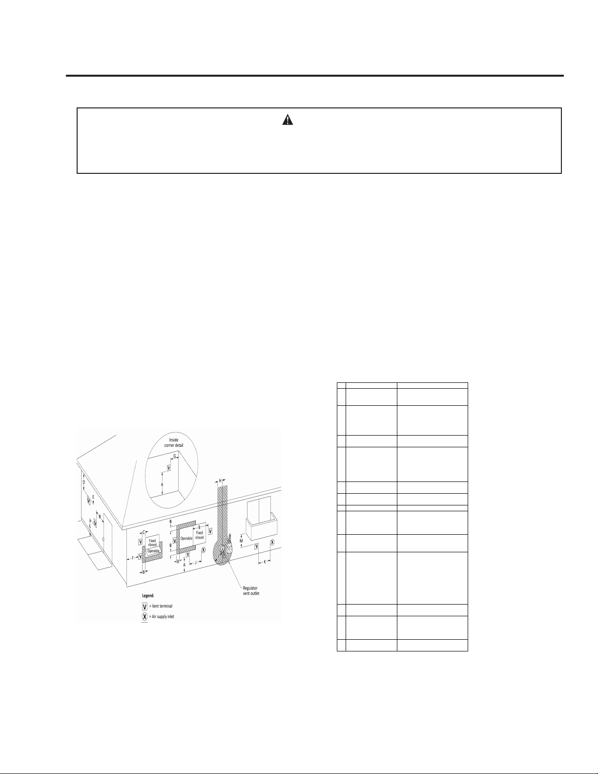
terminal clearance.
Figure 4: Vent Terminal Clearances
US Installations
A=
Clearance above grade,
veranda, porch, deck, or
balcony
12 in (30 cm)
B=
Clearance to window or
door that may be opened
6 in (15 cm) for appliances ≤ 10,000
Btuh (3 kW), 9 in (23 cm) for
appliances > 10,000 Btuh (3 kW) and ≤
50,000 Btuh (15 kW), 12 in (30 cm) for
appliances > 50,000 Btuh (15 kW)
C=
Clearance to Permanently
closed window
12 in (30 cm)*
D=
Vertical Clearance to
ventilated soffit located
above the terminal within a
horizontal distance of 2 ft
(61 cm) from the center
line of the terminal.
12 in (30 cm)*
E=
Clearance to unventilated
soffit
12 in (30 cm)*
F= Clearance to outside corner
2 ft (60 cm)*
G= Clearance to inside corner 18 in (45 cm)*
H=
Clearance to each side of
center line extended above
meter/regulator assembly
Clearance in accordance with local
installation codes and the
requirements of the gas supplier.
I=
Clearance to service
regulator vent outlet
Clearance in accordance with local
installation codes and the
requirements of the gas supplier.
J=
Clearance to
nonmechanical air supply
inlet to building or the
combustion air inlet to any
other appliance
- 6 in (15 cm) for appliances ≤ 10,000
Btuh (3kW),
- 9 in (23 cm) for appliances > 10,000
Btuh (3kW) and ≤ 500,000 Btuh (15
kW),
-12 in (30 cm) for appliances >
500,000 Btuh (15 kW)
K=
Clearance to a mechanical
air supply inlet
3 ft (91 cm) above if within 10 ft (3 m)
horizontally
L=
Clearance above paved
sidewalk or paved driveway
located on public property
Canot be located above public
walkways or other areas where
condensate or vapor can cause a
nusisance or hazard
M=
Clearance under veranda,
porch deck, or balcony
12 in (30 cm)‡
Table 3: Vent Terminal Clearances
1 In accordance with with the current CSA B149.1 Natural Gas and Propane Installation
Code.
2 In accordance with the current ANSI Z223.1 / NFPA 54 National Fuel Gas Code.
3 If locally adopted installation codes specify clearances different than those illustrated,
then the most stringent clearance shall prevail.
†A vent shall not terminate directly above a sidewalk or paved driveway that is located
between two single family dwellings and serves both dwellings.
‡Permitted only if veranda, porch, deck, or balcony is fully open on a minimum of two
sides beneath the floor.
Page 12
SECTION III: PRE-INSTALLATION (CONT)
GAS SUPPLY LINE
Prior to installation, contact your local gas utility to confirm that sufficient gas service is available
for the water heater. The gas meter must have adequate capacity to supply the rated maximum gas
input of the water heater in addition to other gas fired equipment connected to the meter.
Minimum Gas Supply Pressure
The gas supply must be capable of maintaining a minimum pressure at the inlet of the gas control
during water heater operation at maximum input. The pressure will be lowest at the gas control
during water heater operation (i.e. gas is flowing) at maximum input. For natural gas models,
during operation at maximum input, the supply pressure at the gas control must be at least 3.5”
W.C. For LP gas models, during operation at maximum input, the supply pressure at the gas
control must be at least 8” W.C.
Refer to Table 4 for gas supply line sizing. The table shows maximum input in thousands of BTU’s
per hour for various pipe sizes and lengths. The table assumes gas supply pressures of 14” W.C. or
less and a pressure drop of 0.3” W.C.
Table 4: Gas Supply Line Capacity
Minimum gas supply pipe sizes: for models ODOT200 & 250 - 3/4”; model ODOT299 - 1”;
models ODOT300*2 & 400*2 - 1-1/4”; model ODOT500*2 - 1-1/2”.
Maximum Gas Supply Pressure
The gas supply pressure shall never be greater than 14” W.C. Pressures greater than 14” W.C. may
damage the gas control which could cause a fire or explosion.
Refer to Section IV: Installation / Gas Connections for further installation instructions
Nominal
Iron Pipe
Size
(inches)
Internal
Diameter
(inches)
Length of Pipe (feet)
10 20 30 40 50 60 70 80 90 100 125 150 175 200
3/4 0.824 278 190 152 130 115 105 96 90 84 79 72 64 59 55
1 1.049 520 350 285 245 215 195 180 170 160 15 130 120 110 100
1-1/4 1.380 1,050 730 590 500 440 400 370 350 320 305 275 250 225 210
1 1/2 1.610 1,600 1,100 890 760 670 610 560 530 490 460 410 380 350 320
2 2.067 3,050 2,100 1,650 1,450 1,270 1,150 1,050 990 930 870 780 710 650 610
2 1/2 2.469 4,800 3,300 2,700 2,300 2,000 1,850 1,700 1,600 1,500 1,400 1,250 1,130 1,050 980
3 3.068 8,500 5,900 4,700 4,100 3,600 3,250 3,000 2,800 2,600 2,500 2,200 2,000 1,850 1,700
4 4.026 17,500 12,000 9,700 8,300 7,400 6,800 6,200 5,800 5,400 5,100 4,500 4,100 3,800 3,500
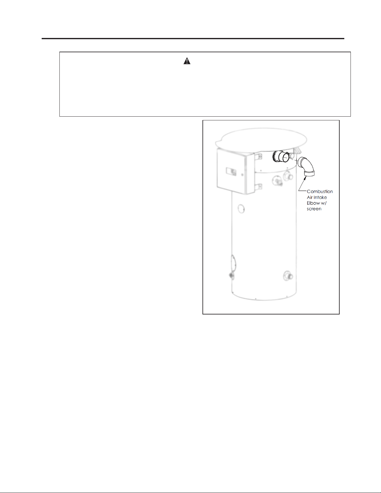
SECTION IV: INSTALLATION
VENT & COMBUSTION AIR INTAKE
DANGER
Failure to properly install the vent and combustion air intake system as outlined in
this manual can result in unsafe operation of the water heater. To avoid the risk of
fire, explosion, or asphyxiation from carbon monoxide, never operate this water
heater unless it is properly vented and has adequate air supply for combustion.
Be sure to inspect the system for proper installation at initial start-up; and at least
annually thereafter. See the Maintenance section for more information.
All of the vent pipe and fittings supplied
with this water heater must be used. The
exhaust vent is factory supplied and
installed. No additional vent pipes or
fittings shall be installed. Connect the
supplied elbow to the combustion air
intake as shown in Figure 5. Cementing
this connection is not required.
Page 13
Figure 5: Vent Assembly

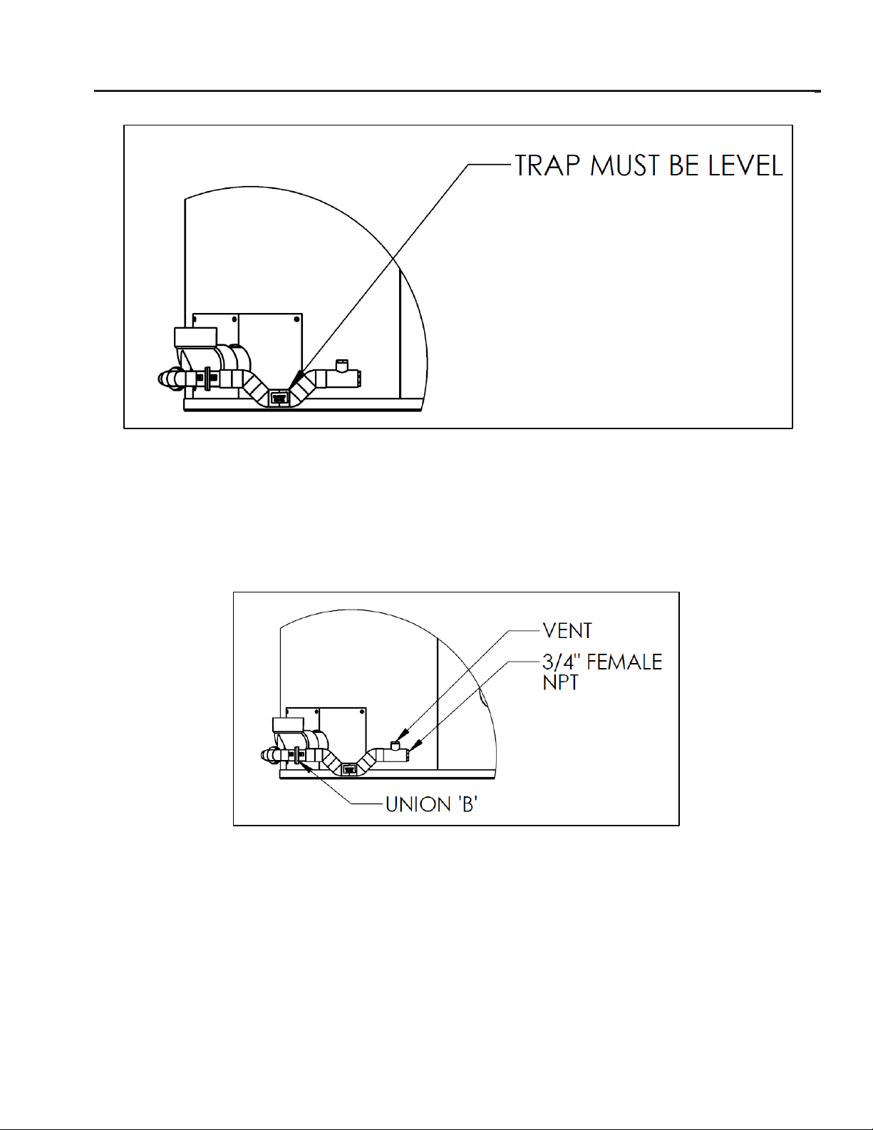
Figure 7: Orientation of the Condensate Trap
Condensate Trap Assembly
This heater comes with the exhaust vent factory installed. Before operation the condensate trap and drain
must be installed along with a suitable drain line.
The condensate trap is made up of three parts and connected by two unions, labeled ‘A’and ‘B’. The drain
elbow is factory installed. There are two orienters included; one with an angle of 135° and another with an
angle of 90°, choose whichever one minimizes the number of fittings required for proper drainage. Figure 6
shows the difference between the two options. Install the orienter of your choice by connecting the union
portions labeled ‘A’.
Figure 6: 135° and 9
0° orienter
Determine which direction minimizes the length of the condensate drain line, and point the orienter in that
direction. Install the trap portion by connecting the union parts labeled ‘B’ so that it is pointing in the
proper direction. See Figure 7 for the top view of both orientation options.
The orientation of the trap portion of the drain is critical for proper venting of gas and drainage of
condensate. This portion must be level after both unions are fully tightened. See Figure 8 for proper final
orientation of the assembly.
SECTION IV: INSTALLATION
CONDENSATE TRAP AND DRAIN
Page 14
Figure 7: Orientation of the Condensate Trap
Condensate Trap Assembly
This heater comes with the exhaust vent factory installed. Before operation the condensate trap and drain
must be installed along with a suitable drain line.
The condensate trap is made up of three parts and connected by two unions, labeled ‘A’and ‘B’. The drain
elbow is factory installed. There are two orienters included; one with an angle of 135° and another with an
angle of 90°, choose whichever one minimizes the number of fittings required for proper drainage. Figure 6
shows the difference between the two options. Install the orienter of your choice by connecting the union
portions labeled ‘A’.
Figure 6: 135° and 9
0° orienter
Determine which direction minimizes the length of the condensate drain line, and point the orienter in that
direction. Install the trap portion by connecting the union parts labeled ‘B’ so that it is pointing in the
proper direction. See Figure 7 for the top view of both orientation options.
The orientation of the trap portion of the drain is critical for proper venting of gas and drainage of
condensate. This portion must be level after both unions are fully tightened. See Figure 8 for proper final
orientation of the assembly.
Figure 6: 90° and 135° Orienter
This heater comes with the exhaust vent factory installed. Before operation the condensate trap
and drain must be installed along with a suitable drain line.
The condensate trap is made up of three parts and connected by two unions, labeled ‘A’ and ‘B’.
The drain elbow is factory installed. There are two orienters included; one with an angle of 135°
and another with an angle of 90°, choose whichever one minimizes the number of fittings required
for proper drainage. Figure 6 shows the difference between the two options. Install the orienter of
your choice by connecting the union portions labeled ‘A’.
Figure 7: Orientation of the Condensate Trap
Determine which direction minimizes the length of the condensate drain line, and point the
orienter in that direction. Install the trap portion by connecting the union parts labeled ‘B’ so that
it is pointing in the proper direction. See Figure 7 for the top view of both orientation options.
The orientation of the trap portion of the drain is critical for proper venting of gas and drainage of
condensate. This portion must be level after both unions are fully tightened. See Figure 8 for proper
final orientation of the assembly.
Page 15
A detailed view of the condensate trap is shown in Figure 9. The discharge portion of the trap is designed
with a vent and threaded ¾” female NPT connection. The trap may be cleaned by disconnecting union B and
the threaded connection, then running water through the trap. Use rigid PVC pipe for the condensate drain
line. The line must slope down, 1/8” per foot, away from the point of connection towards the drain. If there is
insufficient clearance between the connection point and the floor to maintain slope, the heater should be
installed on a concrete slab or use a low-profile condensate pump.
Figure 8: Levelness of Trap
Figure 10: Detailed View
SECTION IV: INSTALLATION
CONDENSATE TRAP AND DRAIN
A detailed view of the condensate trap is shown in Figure 9. The discharge portion of the trap is designed
with a vent and threaded ¾” female NPT connection. The trap may be cleaned by disconnecting union B and
the threaded connection, then running water through the trap. Use rigid PVC pipe for the condensate drain
line. The line must slope down, 1/8” per foot, away from the point of connection towards the drain. If there is
insufficient clearance between the connection point and the floor to maintain slope, the heater should be
installed on a concrete slab or use a low-profile condensate pump.
Figure 8: Levelness of Trap
Figure 10: Detailed View
Figure 8: Levelness of Trap
Figure 9: Detailed View
A detailed view of the condensate trap is shown in Figure 9. The discharge portion of the trap
is designed with a vent and threaded 3/4” female NPT connection. The trap may be cleaned by
disconnecting union B and the threaded connection, then running water through the trap. Use
rigid PVC pipe for the condensate drain line. The line must slope down, 1/8” per foot, away
from the point of connection towards the drain. If there is insufficient clearance between the
connection point and the floor to maintain slope, the heater should be installed on a concrete
slab or use a low-profile condensate pump.
Page 16
SECTION IV: INSTALLATION
CONDENSATE TRAP AND DRAIN
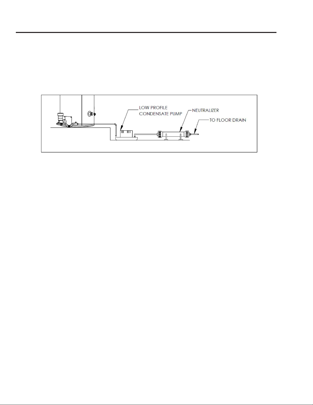
Figure 10: Pump and Neutralizer
Some installations require the use of a condensate neutralizer to reduce the acidity of the
condensate prior to reaching the drain. Figure 10 shows the connection of a condensate
line to a neutralizer. It is recommended that a low profile condensate pump is installed
between the heater and neutralizer to facilitate flow through the neutralizer. For further
details, refer to the instructions provided with the pump and neutralizer.

Page 17
SECTION IV: INSTALLATION
WATER CONNECTIONS
CAUTION
This water heater incorporates fittings that contain a nonmetallic lining. DO NOT apply
heat to these fittings when making sweat connections to the heater. Sweat tubing to
an adapter before securing adapter to any fittings on water heaters.
ALL PIPING SHOULD CONFORM TO LOCAL CODES AND ORDINANCES. It is highly
recommended that unions and shut-off valves are installed at the potable water connections
to allow for isolation and/or movement during service. All piping should be adequately
insulated with an approved material to minimize heat loss.
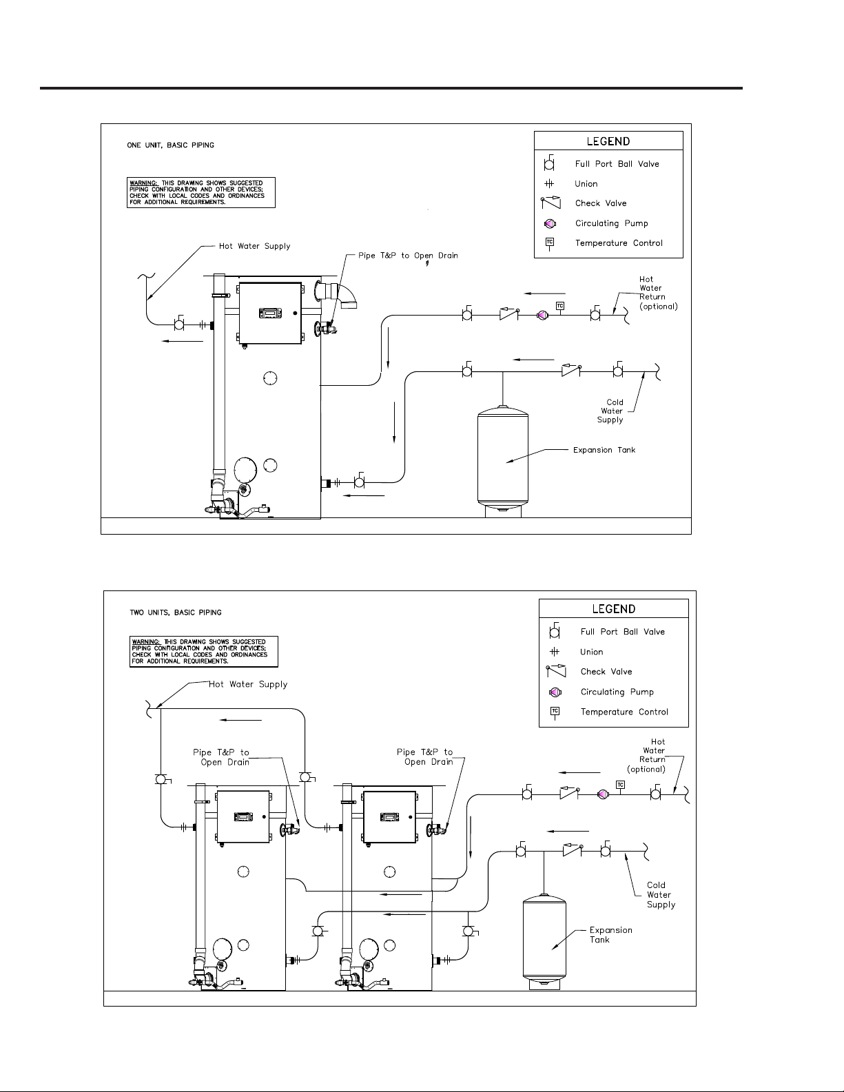
Piping diagrams are provided in Figures 12-15 for a variety of configurations.
POTABLE WATER CONNECTIONS
IMPORTANT: THE WATER HEATER MUST BE FILLED WITH WATER BEFORE
CONNECTING ELECTRIC POWER.
1) Close the main water supply valve before continuing with the installation. After the
main water supply is shut-off, relieve the water line pressure by opening a faucet. Once the
pressure has been relieved, close the faucet. The “Cold” and “Hot” potable water connections
are labeled on the water heater. Install a union and shut-off valve at both potable water
connections. A tempering valve or anti-scald valve should be installed at the potable water
outlet and used according to the manufacturer’s specifications to prevent scalding.
IMPORTANT: The water heater contains factory installed
pipe nipples at the hot outlet connections. These pipes
were tightened to proper orientation at the factory. DO
NOT ROTATE THESE PIPES WHEN CONNECTING FITTINGS
IN THE FIELD. The black indicator line on the side of the
factory installed pipe nipple must be in line with the arrow
on the label shown in Figure 11. If orientation is not correct
there will be a reduction in water heater performance.
2) If a backflow preventer, check valve, or pressure regulating valve is required in the cold
water supply, a properly sized expansion tank must be installed to control thermal expansion.
Do not operate the water heater in a closed system without installing a thermal expansion
tank. Follow the expansion tank manufacturer’s recommendations when selecting a tank for
your system.
3) Following installation of the water lines, open the main water supply valve and fill the
water heater. Open several hot water faucets to relieve air from the system. After water is
flowing through the faucets and the system is void of air, close the faucets and check for water
leaks in the system.
Note: Do not try to heat hard water as this will drastically reduce heater life. Install a water
softener or other scale reducing water treatment system if the water heater is being installed in
a hard water area (water hardness higher than seven grains).
)L
J
XUH +RW 2XWOHW 3LSH 1LSSOH 2ULHQWDWLRQ
Figure 11: Hot Outlet Pipe
Nipple Orientation
Page 18
SECTION IV: INSTALLATION
Figure 12: Piping Diagram One Unit
Figure 13: Piping Diagram Two Units

Page 19
SECTION IV: INSTALLATION
Figure 14: Piping Diagram Three Units
Figure 15: Piping Diagram One Unit with Storage Tank

Page 20
SECTION IV: INSTALLATION
GAS CONNECTIONS
CAUTION
Do not use this water heater with any gas other than the type listed on the rating label.
Check the rating label on the front of the water heater and make sure the gas to be
used matches the gas stated on the rating label. Consult your local gas company or
Bock Water Heaters with any questions.
A manual valve, union, and a sediment
trap shall be provided in front of the
gas valve. All gas piping must conform
to local codes and/or the National Fuel
Gas Code ANSI 223.1/NFPA 54 or CSA
B149.1. Figure 16 shows the installation
of a sediment trap to the gas piping on
the water heater.
The gas supply piping to the heater
must be sized such that the pressure at
the valve is sufficient when all other
appliances are operating. Undersized
gas piping will reduce water heater
performance and result in nuisance
lockouts. Refer to Section III: Pre-Instal-
lation / Gas Supply Line for pipe size requirements.
Verify that the gas service and meter are sized properly for the total load. If the gas supply
pressure is greater than 14” W.C., the water heater must have a supply gas regulator installed
in the gas supply line for each water heater. The regulator must be rated at or above the input
rating (Btu/hr) of the water heater that it serves. Inlet and outlet connections on the regulator
shall not be less than the minimum gas supply line size for the water heater. The Maxitrol
325-7 series of regulators with 1-1/4” or 1-1/2” connections is recommended.
For ease of measurement, install a tee with a pipe fitting and a manual shutoff valve between
the main manual shut-off valve to the water heater and the pressure regulator. The pipe
fitting should be adaptable to a pressure gauge for measuring incoming gas pressure. If further
measurement of gas pressure is required due to lack of adequate pressure, measurement at the
inlet of the gas control is recommended. Refer to Section III: Pre-Installation / Gas Supply Line
for minimum pressure requirements.
During pressure testing of the gas supply piping, close the manual gas shut-off valve to the
water heater. Test pressure shall not exceed 1⁄2PSIG (14” W.C). The gas control is only rated
for 1⁄2PSIG. To test at a pressure greater than 1⁄2PSIG, close the manual shut-off valve and
disconnect the gas control. Turn on gas and inspect piping for leaks by “painting” each joint
with a soapy water solution and check for bubbles.
WARNING
DO NOT use an open flame to check for leaks. Serious injury or death could result from
fire or explosion.
The pipe thread compound that is used on gas piping must be of the type resistant to
propane gas. Do not use teflon tape on gas piping.
Figure 16: Gas Piping with Sediment Trap
This manual suits for next models
11
Table of contents


