by
Hotdoor and Phormalab are registered brands of
Urbani srl, Via Garibaldi 67/c 25065 Lumezzane (BS) Italia
Tel. (+39) 030,872181 Fax (+39) 030.872748
IT – ISTRUZIONI DI MONTAGGIO
Montaggio apparecchio riscaldante Hotdoor con
attacchi a piantana doppia HCA21-22-23
Attenzione: l’apparecchio riscaldante hotdoor va montato ed orientato
a distanza di sicurezza da muri, pareti o oggetti infiammabili. Seguire
le indicazioni contenute nel libretto di istruzioni dell’apparecchio
scaldante Hotdoor.
1-2. Pezzi contenuti nella confezione:
A. Due apparecchi scaldanti Hotdoor
B. Quattro tubi di sostegno B1+B2
C. Base
D. Due tubi di base
E. Coperchio
F. Due raccordi a tenuta stagna
G. Un raccordo a tre vie con cavi montati
H. Due viti M3
I. Sei viti M4
J. Due viti M6 con rondella
K. Tre viti M8
L. Due distanziali in ottone
3. Scegliere la posizione di orientamento dell’apparecchio: l’apparecchio
può essere installato sia in posizione longitudinale che trasversale,
svitando le due viti M6 che fissano l’aggancio superiore alla lampada e
ruotando lo stesso aggancio di 90°, avendo cura di non torcere il cavo di
alimentazione, e riavvitando poi lo snodo nella nuova posizione con le
stesse viti
4. Per ogni lampada inserire l'estremità libera del cavo elettrico proveniente
dalla lampada A nell'apposita asola di entrata del tubo di sostegno B1 e
farla scorrere al suo interno, fino a che dentro tale asola si inserisca anche
la guaina in silicone che esce dalla lampada (tripla protezione del cavo
elettrico).
5. Fissare ogni lampada A all’estremità del tubo di sostegno B1, serrando
la vite J. La vite deve essere montata con l’apposita rondella zigrinata in
dotazione. Al termine del montaggio la vite J dovrà essere stretta in modo
che la lampada non possa accidentalmente ruotare e surriscaldare pareti,
elementi potenzialmente infiammabili o prese di corrente.
6. Il cavo deve essere completamente estratto dal tubo B1 ed in seguito
inserito nel tubo B2 ed estratto completamente dall'altro lato del tubo.
Fissare i tubi B1 e B2 con 2 viti I.
7. Tenendo i pezzi su un cartone o una protezione antigraffio, fissare i tubi
D alla base C, serrando con forza le sei viti lunghe K e posizionando le
asole di passaggio cavo verso il centro della base C. Avvitare i due
distanziali L ai tubi di base D
8. Inserire i due cavi di alimentazione collegati al raccordo a T (G) nei tubi
D inserendoli nelle asole di passaggio, facendoli fuoriuscire dall’altro lato
per 20/30 cm.
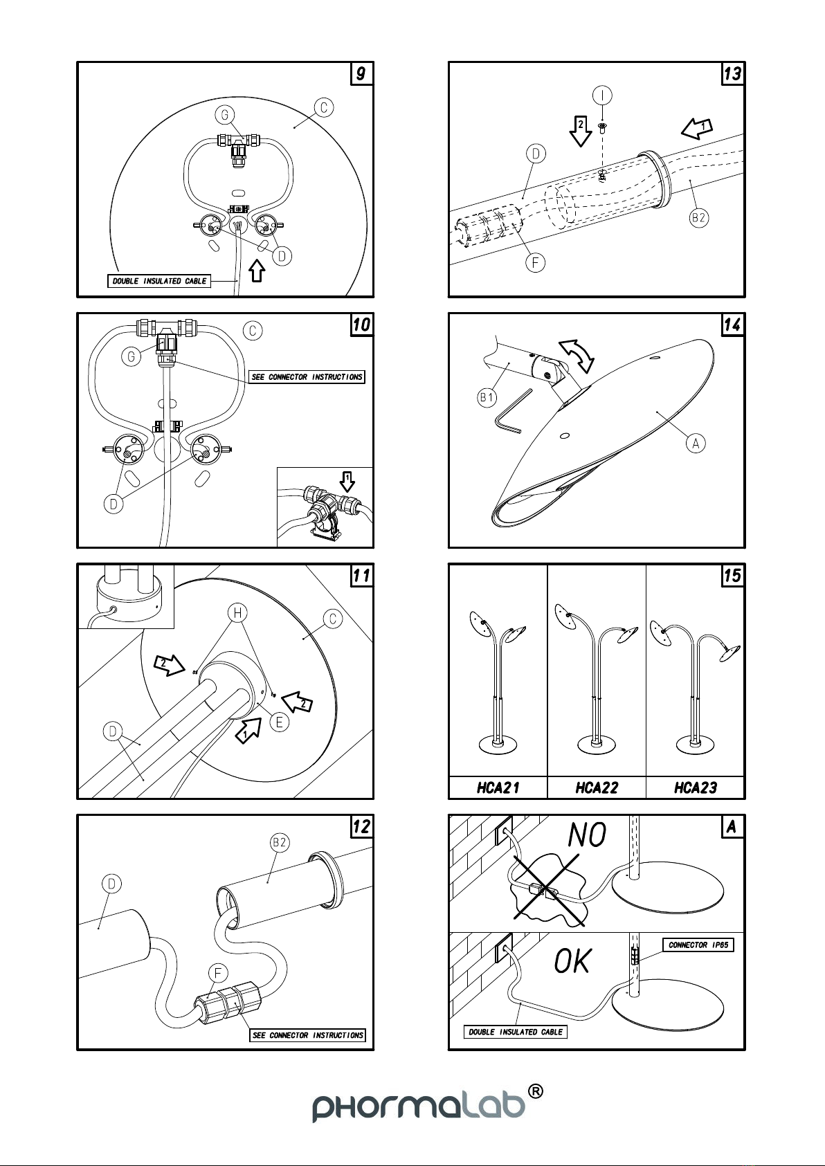
9. Collegare il cavo proveniente dalla rete eletrica, facendolo passare nel
ponticello fermacavi e congiungendolo al raccordo a tre vie (G), seguendo
le apposite istruzioni.
Attenzione: Dall’impianto deve sempre arrivare un cavo in
doppio isolamento, di tipo HAR (sezione 3x2.5 mm2),
diametro 9-13.5 mm onde evitare ogni rischio di mettere in
tensione le parti metalliche dell’attacco. Nel caso in cui il
cavo proveniente dall’impianto domestico non fosse in
doppio isolamento, provvedere ad adeguarlo prima di montare la
lampada.
10. Posizionare il raccordo a tre vie G nella clip che va preventivamente
fissata alla base C; il ponticello fermacavi va saldamente fissato alla base
C per impedire lo scorrimento o lo strappo accidentale del cavo di
alimentazione.
11. Far scivolare il coperchio E lungo i due tubi di base D fino a che si
appoggia alla base C, e fissarlo ai distanziali in ottone con le viti H. Il cavo
proveniente dalla rete elettrica deve passare attraverso l’asola presente nel
coperchio.
12. Avvicinare la base con i tubi ad essa montati (C+D) ai due tubi con le
lampade montate (B1+B2+A) e tagliare i cavi elettrici ad una lunghezza
sufficiente per il raccordo dei cavi. Collegare i cavi con i raccordi a tenuta F,
seguendo le istruzioni contenute nella confezione dei raccordi stessi e
avendo cura di accoppiare fase con fase, neutro con neutro, e terra con
terra. Avvitare i dadi di serraggio del raccordo in modo di garantire la tenuta
stagna dello stesso.
13. Far scivolare i due raccordi all’interno dei due tubi D (verso la base) per
20/30 cm. Inserire infine i tubi B1+B2 nei tubi di base D e fissarli con le viti
I.
14. Portare la piantana in posizione verticale e orientare le lampade nelle
direzioni desiderate, serrando definitivamente le viti J.
15. La lampada hotdoor a stelo doppio è ora montata e pronta per l’uso. In
caso si voglia fissare la lampada al pavimento con tasselli ad espansione,
utilizzare una o più delle tre asole centrali della base C.
ATTENZIONE: in caso di uso esterno, applicare sempre connessioni a
tenuta stagna con grado di protezione adeguato (fig. A)
EN – ASSEMBLY INSTRUCTIONS
Assembly of infrared heater “hotdoor” with
double pedestal HCA21-22-23
Warning: the heaters must be installed and oriented with minimum
clearance distance from walls, ceilings and inflammable objects.
Follow the use instructions of the Hotdoor heater (included in the box
of Hotdoor).
1-2. Parts list:
A. Two Hotdoor infrared heaters
B. Two support tubes
C. Basis
D. Two basis tubes
E. Cover
F. Two waterproof fitting for electric cables
G. One Waterproof "Tee" fitting with pre-mounted cables
H. Two M3 screws
I. Six M4 screws
J. Two M6 screws with washers
K. Three M8 screws
L. Two brass spacers
3. Choose orientation of the heaters: Hotdoor can be installed either
longitudinally or transversely, unscrewing the two M6 screws holding the
upper joint to the heater and rotating it for 90°, taking care of not twisting
the power cord, and finally tightening the joint in the new position with same
screws.
4. For each heater, insert the free end of the electric cord coming from the
heater A into the slot of the support tube B1 and slide inside it, until that