Page 2
• DO NOT plug the heater into any other cord
connected device such as a power strip, surge
protector, multiple outlet adapter, grounding
adapter, outlet-type air fresheners or extension
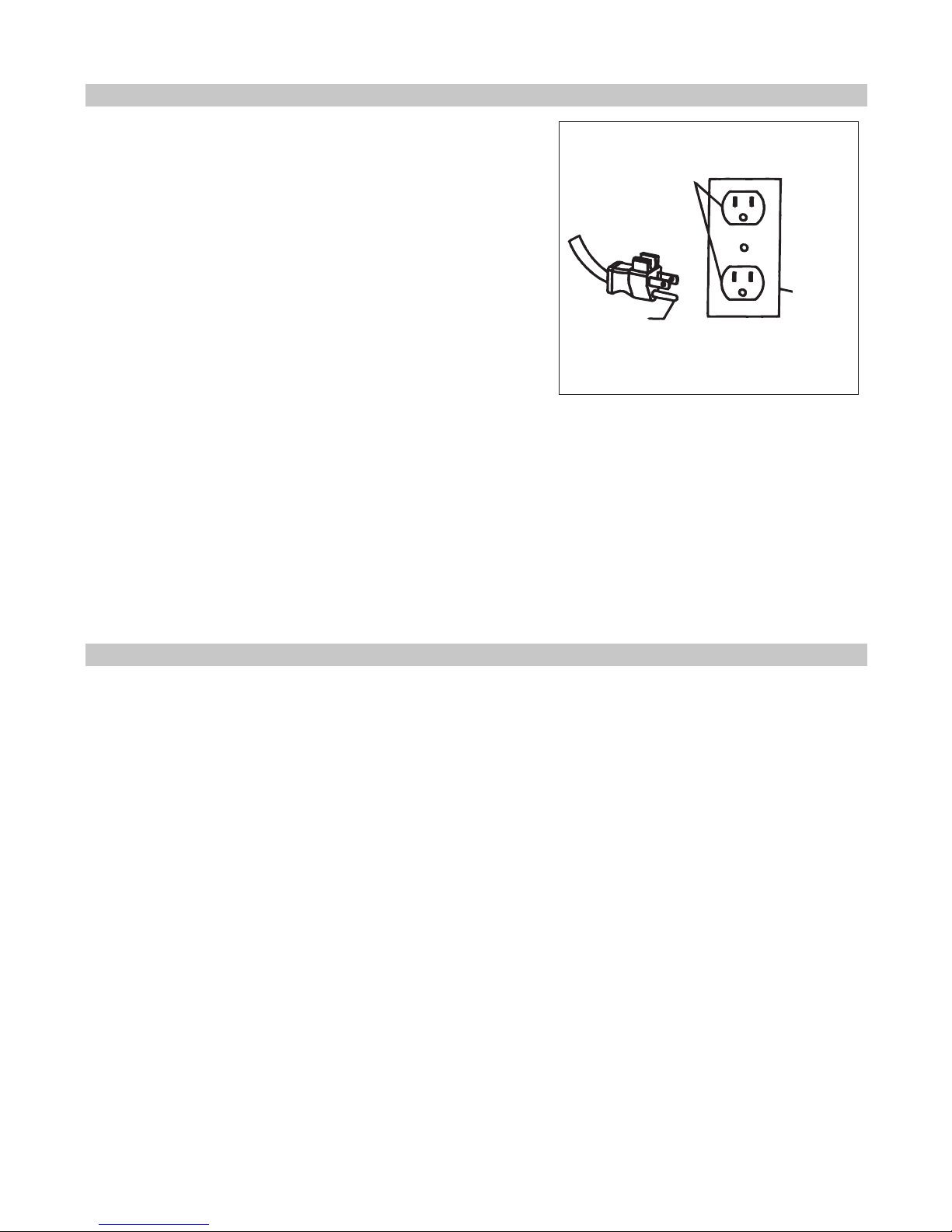
cords. Plug into a 3-prong, 120V 15 amp or
higher grounded circuit receptacle only.
• DO NOT plug the heater into a loose tting or
broken receptacle.
• DO NOT alter the heater’s design or you will
void the warranty.
• DO NOT block the front or rear of the heater.
• DO NOT place anything directly in front of the
heater.
• DO NOT cover the unit as this may block airow
and cause the heater to malfunction.
• DO NOT use the heater outdoors or in
construction sites.
• DO NOT force the lter to dry using any
alternative methods when performing lter
maintenance, doing so could damage the lter.
• DO NOT run the power cord under carpeting.
• DO NOT cover the power cord with throw rugs,
runners or similar coverings. Arrange the cord
away from trafc areas and where it will not be
tripped over.
• DO NOT insert or allow foreign objects to enter
any ventilation or exhaust opening as this may
cause an electric shock or re, or damage the
heater.
• DO NOT operate this heater with a damaged
cord or plug or after the heater malfunctions,
has been dropped or damaged in any
manner. Return heater to an authorized retailer
for examination, electrical or mechanical
adjustment or repair.
• DO NOT use this heater in areas where
gasoline, paint or ammable liquids are used or
stored. A heater has hot or arcing parts inside.
• This heater is hot when in use. To avoid burns,
do not let bare skin touch hot surfaces.
• Always unplug this heater when it is not in use.
To disconnect the heater, turn controls to off
then remove plug from the outlet.
• To prevent a possible re, do not block air
intakes or exhaust in any manner. Do not use
on soft surfaces, like a bed where openings
may become blocked.
• Keep combustible materials such as furniture,
pillows, bedding, clothes, curtains and paper
at least 3 feet from the front of the heater and
keep them away from the sides and the rear.
• Use this heater only as described in this
manual. Any other use not recommended by
the manufacturer may cause re, electrical
shock or injury to persons.
• Avoid the use of an extension cord because the
extension cord may overheat and cause a risk
of re.
• This heater is for use on 120 volt grounded
outlets. An adapter should not be used.
• This heater must be located near a socket
outlet.
• Extreme caution is necessary when any
heater is used by or near children or invalids
and whenever the heater is left operating and
unattended.
• This heater is not intended for use in
bathrooms, laundry areas and similar indoor
locations. Never locate the heater where it may
fall into a bathtub, shower, swimming pool or
other water container.
• Connect to properly grounded outlets only.
SAVE THESE INSTRUCTIONS.
WARNING:
IMPORTANT SAFETY INSTRUCTIONS
When using an electrical appliance, basic precautions should always be followed, including
the following:
READ ALL INSTRUCTIONS BEFORE
USING THIS APPLIANCE
The manufacturer cannot accept responsibility for damage
caused when the appliance is not used according to the
instructions, or for uses other than those for which it
was intended.
To reduce the risk of fire, electric shock or injury:
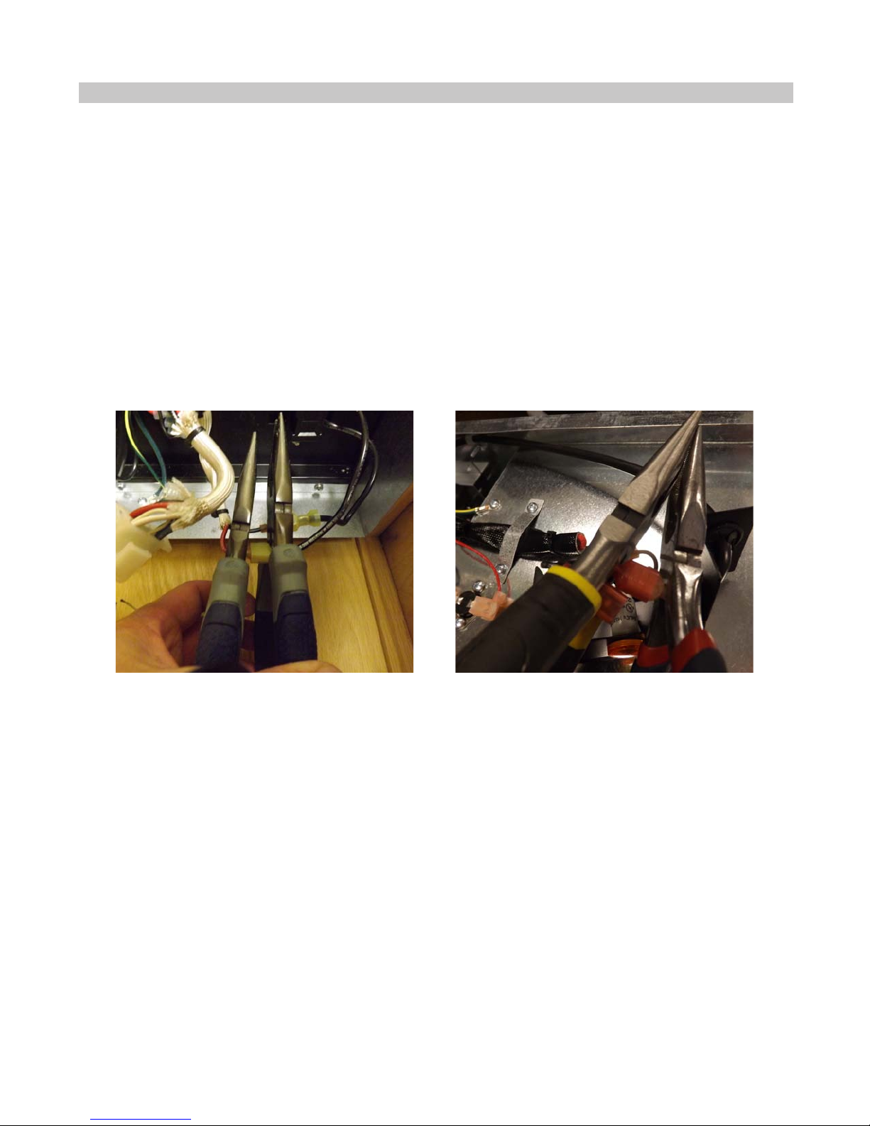
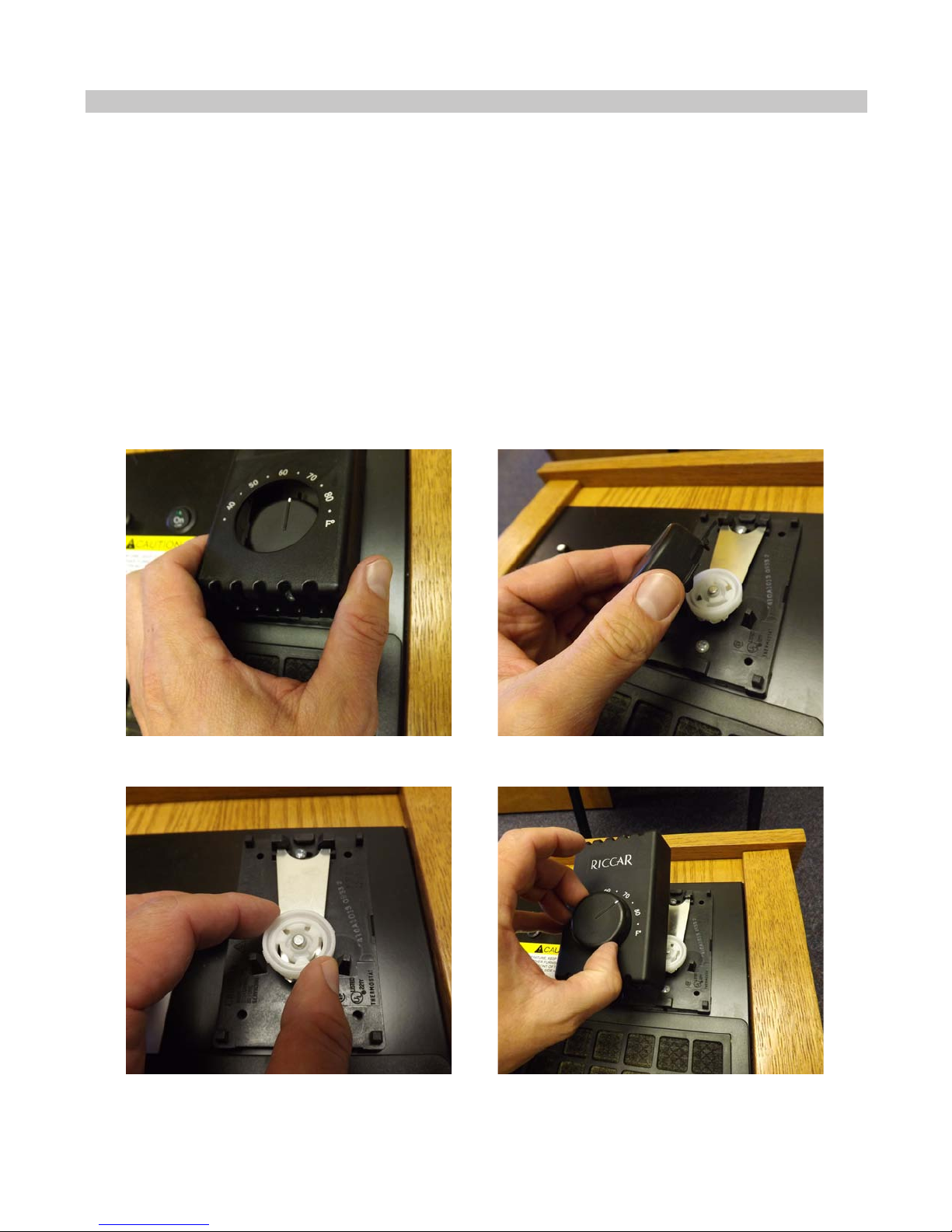
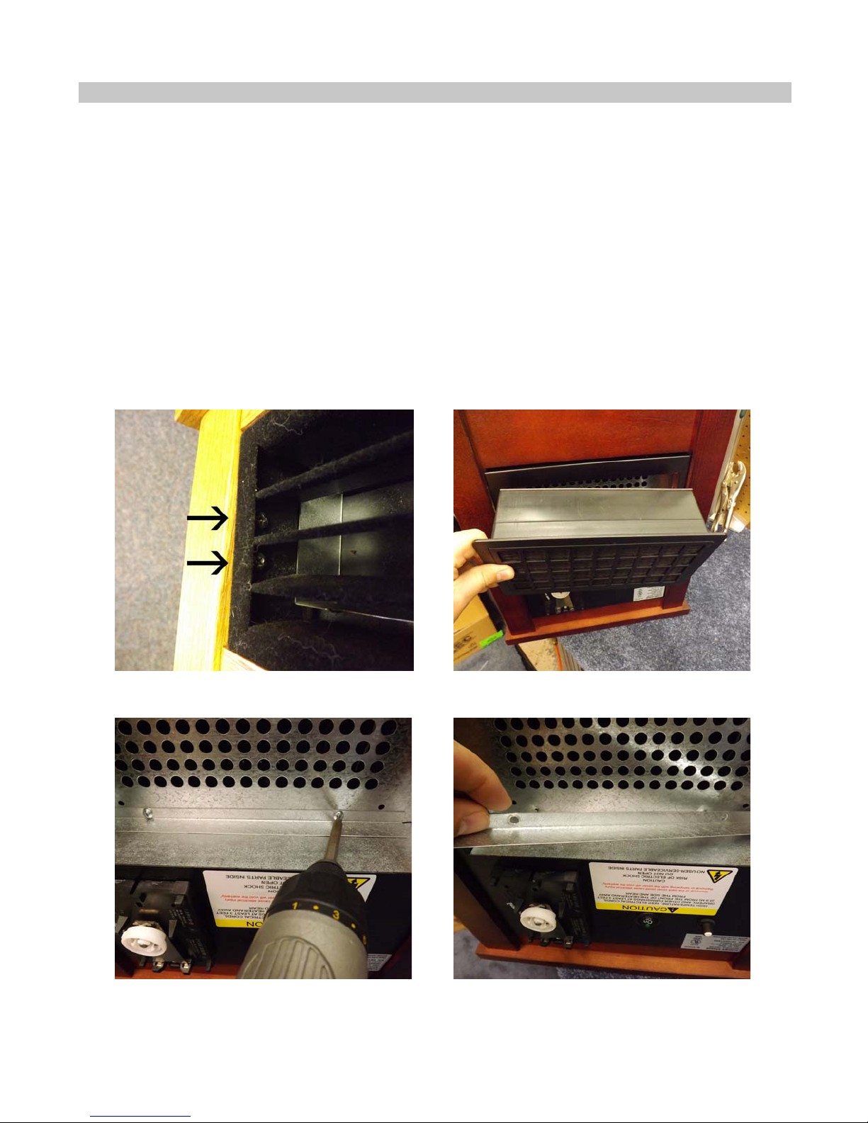
A. Safety Instructions
I. Basic Assembly and Operation