BOCK OptiTHERM OT125 User manual

Page 1
Common Vent Kit Installation Manual
For 2 or 3 OptiTHERM Models OT125-199
Rev 0 02/03/2021

Page 2
The proper installation, use and servicing of this water heater is very important to
your safety and the safety of others.
This is the safety alert symbol. Statements following this symbol contain
important safety information. Obey all safety messages that follow this symbol to
avoid possible injury or death. Important safety information will be preceded by
the safety alert symbol and the words DANGER, WARNING, CAUTION, OR
NOTICE.
DANGER indicates an imminently hazardous situation which, if not avoided,
will result in serious injury or death.
WARNING indicates a potentially hazardous situation which, if not avoided,
could result in serious injury or death.
CAUTION indicates a hazardous situation which, if not avoided, could result in
minor or moderate injury.
NOTICE calls attention to observe a specified procedure.
DANGER
Failure to properly install the vent and combustion air intake system, especially regarding proper
installation of the Non-Return Valve, can result in unsafe operation of the water heater. To avoid the risk
of fire, explosion, or asphyxiation from carbon monoxide, never operate this water heater unless it is
properly vented and has adequate air supply for combustion. Be sure to inspect the system for proper
installation at initial start-up; and at least annually thereafter. See the Maintenance section for more
information.
NOTICE
DO NOT use this Common Vent Kit to combine the vents of water heaters which use different fuel types.
NOTICE
DO NOT use this Common Vent Kit to combine the vents of water heaters outside of the model family
OT125-199. Using this Common Vent Kit to combine the vents of water heaters with a rated input
greater than 199,000 BTU/Hr may result in excess pressures in the common vent.
NOTICE
DO NOT use this Common Vent Kit to combine the vents of more than three water heaters outside of
the model family OT125-199. Failure to comply with this requirement may result in excess pressures in
the common vent.

Page 3
Contents
I. Introduction..........................................................................................................................................4
II. Supplemental Information...................................................................................................................4
III. Overview...........................................................................................................................................4
a. Definitions.........................................................................................................................................4
b. Configurations...................................................................................................................................5
Bock OptiTherm Common Vent Kit –Parts List ........................................................................................8
Optional Connector and Header Parts:.....................................................................................................9
IV. Installation Instructions .................................................................................................................10
Pre-Installation........................................................................................................................................10
Polypropylene Pipe Connections ............................................................................................................15
Gasket Placement ...............................................................................................................................15
Field Cutting Polypropylene Vent Lengths..........................................................................................15
Joint Connections................................................................................................................................16
Exhaust Connectors and Header.............................................................................................................17
Intake Connectors and Header ...............................................................................................................20
Condensation Management ...................................................................................................................23
Common Vent.........................................................................................................................................26
Terminations...........................................................................................................................................27
V. Maintenance.......................................................................................................................................32
Condensate Traps ...................................................................................................................................32
Inspect the venting system.....................................................................................................................32
Non-Return Valve....................................................................................................................................32
Combustion System ................................................................................................................................33
VI. Troubleshooting .............................................................................................................................33
VII. Warranty.........................................................................................................................................34

Page 4
I. Introduction
The Bock OptiTherm Common Vent Kit can be used to direct vent up to three appliances in the
model category OT125-OT199 provided they use the same fuel type and are not high altitude
versions. This document describes two heater direct vent, and three heater direct vent kits.
These kits are intended to combine the intake and exhaust vents of two or three OptiTherm
water heaters with the maximum input rates between 125,000 and 199,000 BTU/hr for the
purpose of reducing the number of wall terminations required.
Combining heaters which have different input rates is permissible, but it is not permissible to
combine fuel types in a common vent system. For example, it is permissible to combine the
vents of an OT125N, OT150N, and OT199N because they all use the same fuel type, but it is not
permissible to combine the vents of an OT125LP, OT150LP, and OT199N because they don’t all
share the same fuel type.
This manual was supplied with the Common Vent Kit in an adhesive backed sleeve. Once
installation is complete, remove the paper adhesive cover and attach the sleeve with this
manual inside to one of the water heaters underneath the standard installation manual sleeve.
II. Supplemental Information
This installation manual supplements the standard installation manual provided with each
OptiTherm water heater. The installation of a water heater with a Polypropylene Common Vent
Kit must satisfy all the requirements in the standard installation manual and the requirements
in this document. Additionally, installation of these kits shall comply with all local codes. In the
absence of local codes, refer to the latest edition of NFPA 54/ANSI Z223.1 or CSA B149. It is permissible
to switch to a different approved vent material after the manifold is constructed with the
supplied polypropylene components given the installation complies with applicable codes.
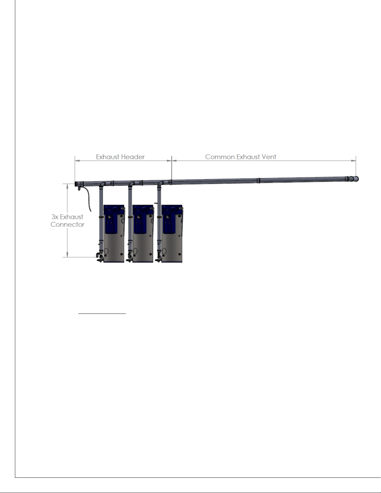
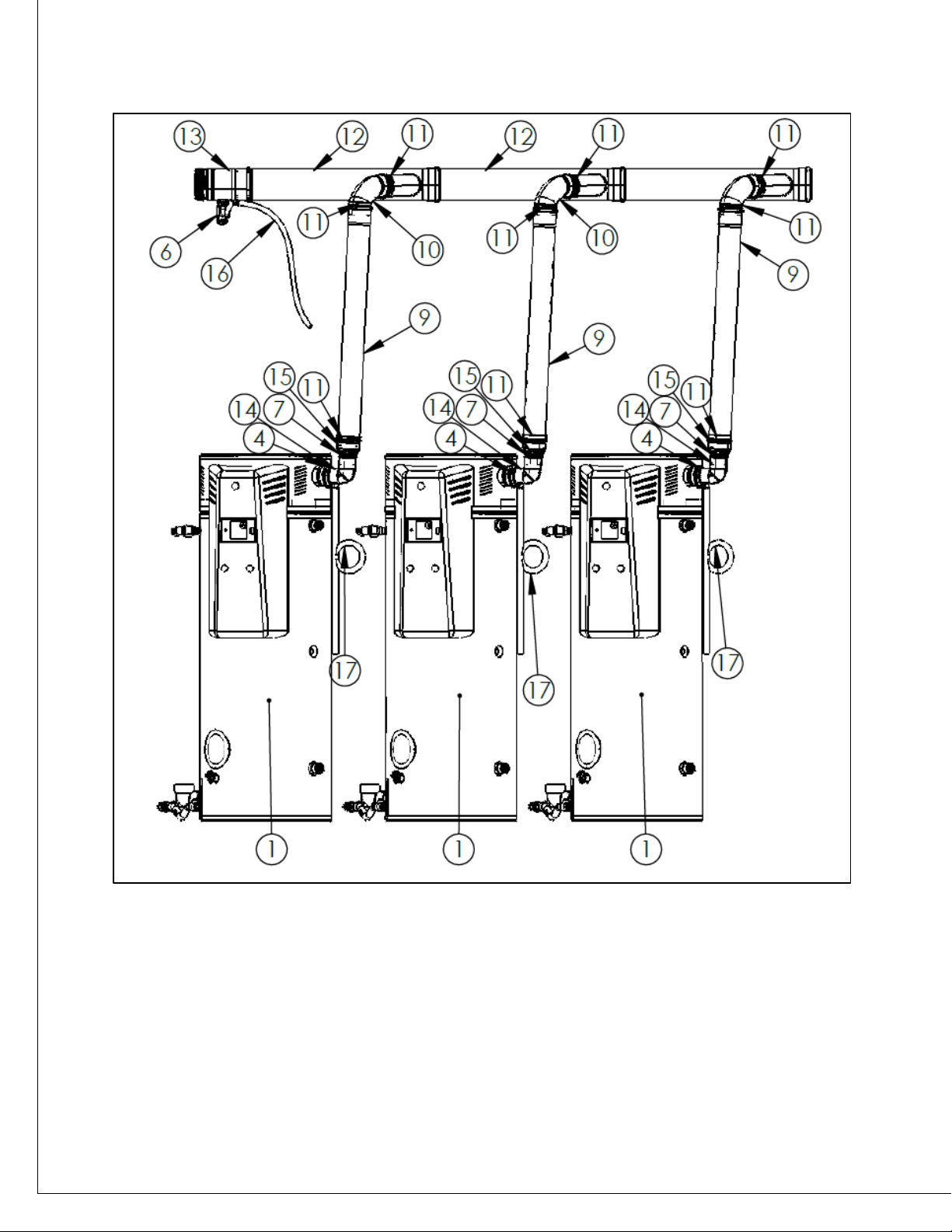
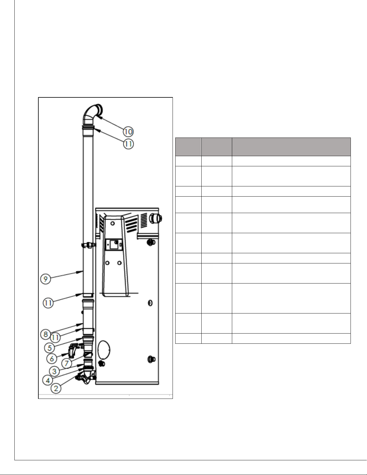
III. Overview
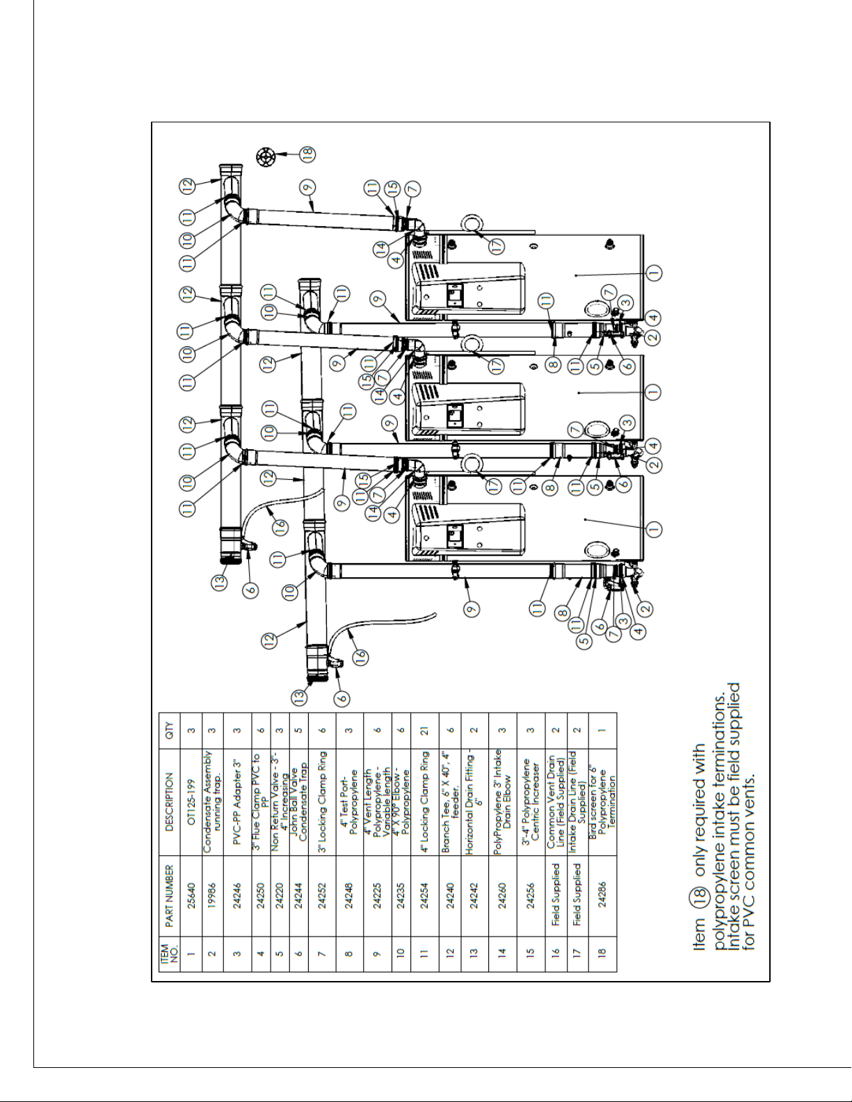
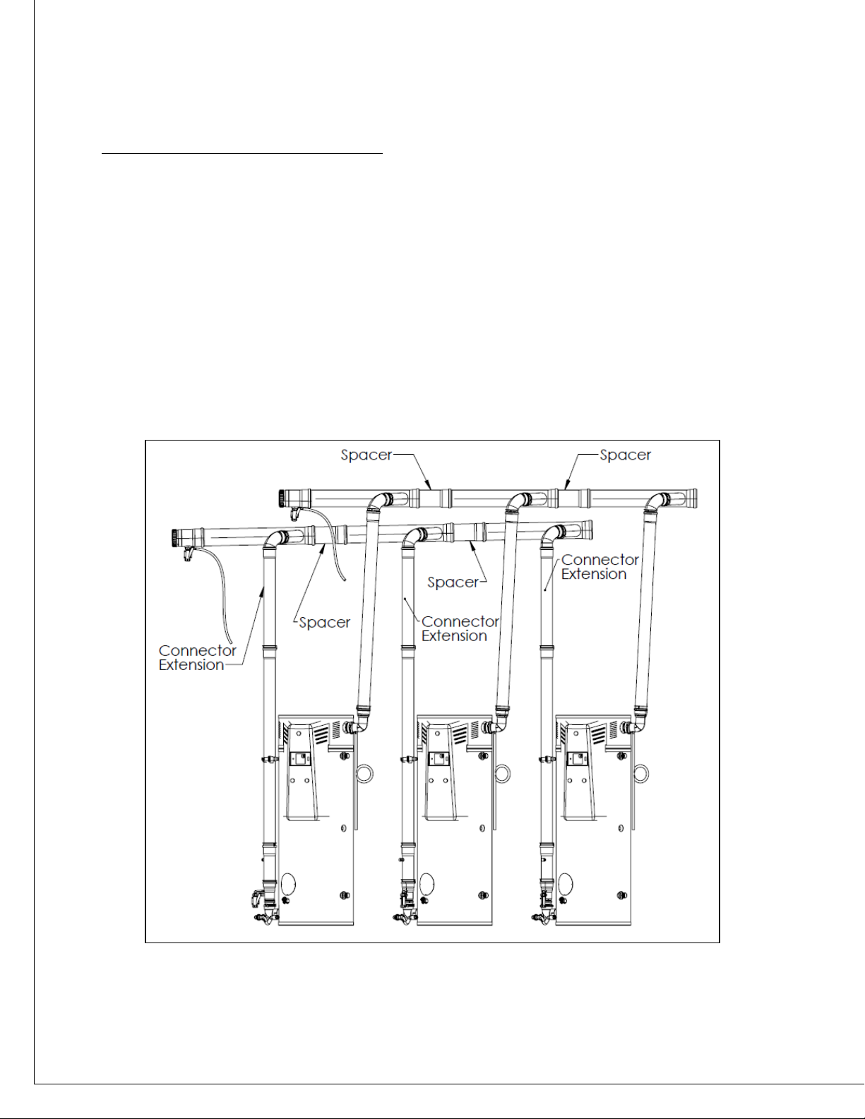
The Bock OptiTherm Common Vent Kits include all necessary parts to properly connect the vents
of two or three heaters and begin the common vent. These parts make up the vent sections
called connectors and headers.
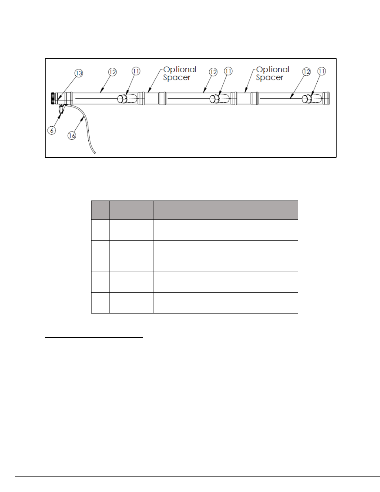
a. Definitions
•Common vent: The section of intake/exhaust vent which carries combustion air/flue
gasses of multiple water heaters from/to outside. This section does not include the
Header section of the vent, is made up entirely of 6” vent pipes and fittings and is unique
to each installation.

Page 5
•Header: The horizontal section of intake/exhaust vent which distributes/collects
combustion air/ flue gasses to/from the water heaters. This section is primarily made up
of branch tees and optional spacers and is nominally 6” in diameter.
•Connector: The vertical section of intake/exhaust vent which connects a water heater to
a header. This section is made up of several adapting fittings and a vertical section of 4”
pipe which dictates how high the header is.
•Manifold: The section of intake/exhaust vent made up of the connectors and the
header.
b. Configurations
There are two configurations for proper installation of the Bock Common Vent Kit which
allow you to configure two or three heaters. Standard heater spacing is 40” apart (center to
center). If additional clearance is needed, a spacer piece must be purchased separately and
inserted between the branch tees for each heater.
Note: Intake vent not shown for
simplicity.
Figure 1: Connector, Header, Common Vent, Manifold Diagram.

Page 6
Figure 2: Common Vent Kit assembly, 3 heater configuration

Page 7
Figure 3: Common Vent Kit assembly, 2 heater configuration

Page 8
Bock OptiTherm Common Vent Kit –Parts List
The parts list below includes all the polypropylene vent parts necessary to connect two or three
heaters to the common vent. These parts are necessary for the headers and connectors. Some
non-polypropylene parts are also necessary for proper installation. These are either shipped
with the heater or are field supplied. In some situations, additional polypropylene parts may be
necessary to complete the manifold. Further polypropylene parts will be necessary to complete
the common vent after the intake and exhaust manifolds have been constructed if a
polypropylene common vent will be used.
Table 1 references the overall installation figures on pages 6 and 7.
Table 1: Common Vent Kit Bill of Materials
ITEM
NO.
PART
NUMBER
DESCRIPTION
Two heater
direct vent -
40" spacing
Three heater
direct vent -
40" spacing
3
24246
PVC-PP Adapter 3"
2
3
4
24250
3" Flue Clamp PVC to PP
4
3
5
24220
Non Return Valve - 3"-
4" Increasing
2
3
6
24244
John Ball Valve
Condensate Trap
4
5
7
24252
3" Locking Clamp Ring
4
6
8
24248
4" Test Port- Polypropylene
2
3
9
24225
4" Vent Length Polypropylene -
6 ft Long
4
6
10
24235
4" X 87° Elbow -
Polypropylene
4
6
11
24254
4" Locking Clamp Ring
14
21
12
24240
Branch Tee, 6" X 40", 4" feeder.
4
6
13
24242
Horizontal Drain Fitting - 6"
2
2
14
24260
Polypropylene 3" Intake
Drain Elbow
2
3
15
24256
3"-4" Polypropylene
centric increaser
2
3
18
24286
6” bird screen for polypropylene
pipe
1
1

Page 9
Optional Connector and Header Parts:
In some cases, additional parts may be necessary to properly create the connectors and headers based
on your application.
•If the heaters must be spaced farther than 41” apart, an additional 6” X 1’
polypropylene piece (PN: 24262) will be needed to accommodate the increased
distance. See the part identified as “spacer” in Figure 4.
•If the exhaust header must be taller than the standard 8’, you may add up to one
section of 4” x 3’ PP pipe (PN: 24230) to increase the height to a maximum of 11’. See
the part identified as “Connector Extension.” Intake headers may not be raised in this
fashion.
oIf using an additional piece of pipe in this fashion an additional 4” connector ring
(Item 11; PN: 24254) is required to lock the pipes together.
Figure 4: Optional manifold components - not included in kit

Page 10
Common Vent Parts
Additional parts will be required to properly create the common vent out of polypropylene. All pipes and
fittings in the common vent shall be 6” diameter pieces. If using polypropylene, Table 2 shows several
parts that may be used. If using a different approved vent material, pipes and fittings must be field
supplied. The 6” PP-PVC termination adapter shall be used to convert to PVC if necessary.
Table 2: Additional polypropylene parts and equivalent lengths
Part Description
Part Number
Equivalent Length (ft)
6” PP (6’)
24270
6
6” PP (3’)
24268
3
6” PP (2’)
24266
2
6” PP (1’)
24264
1
90 ° PP Elbow 6” diameter
24272
5
45° PP Elbow 6” diameter
24274
2.5
30° PP Elbow 6” diameter
24276
1.67
15° PP Elbow 6” diameter
24278
1
6” PP-PVC termination adapter
24280
1
Low Profile Wall Termination (6”)
24282
N/A
PP 6” Bird Screen
24286
0
Centrocerin Lubricant
24258
N/A
IV. Installation Instructions
Pre-Installation
The following describes the steps required for proper installation of the Bock OptiTherm
Common Vent Kit. The components of this kit are made of polypropylene and seal with gaskets
which do not require any adhesive.
All water heaters that will be a part of the common vent system must be next to each other and
facing the same direction. The water heaters must be installed in a line with equal spacing
between them. They should each be located between 40” and 52” apart from one another
(measured on-center). Installing the heaters in this way allows them to have their exhaust and
intake vents combined. If heaters are more than 41”apart from one another it will be
necessary to add a spacer piece (PN: 24262) between the branch tees. The spacer piece must
be purchased separately from the Bock Water Heaters website. Failing to add this spacer piece
will add stress to the joints, could adversely affect condensate drainage, prevent proper
connections, or allow the connections to fail.
The common vents should be planned to minimize the length and number of fittings required
to terminate both vents outside and should be properly located to prevent cross
contamination. The maximum equivalent length of each of the common vents is 75 feet (not

Page 11
including the headers and connectors). See Table 3 for the equivalent lengths of several parts
which may be required to properly vent the heaters.
Kit Size
Vent Section
Fuel
Type
Diameter (in)
Minimum
Equivalent
Length (ft)
Maximum
Equivalent
Length (ft)
Two Heater,
Three Heater
Intake Common
Vent
NAT or
LP
6
15
75
Exhaust
Common Vent
NAT or
LP
6
15
75
The following images depict the manifolds which are constructed from the Common Vent Kits.
Figure 5 shows the intake manifold and Figure 6 shows the exhaust manifold. Both are required
for proper installation of a common vent. After installation of the headers, the common vent
can be connected. The common vent sections shall have a maximum equivalent vent length of
75’ for a total maximum equivalent vent length of 150’ (not including the required header
sections).
CAUTION:
Venting a common vent system is only permissible in a Direct Vent configuration where both intake
and exhaust vents terminate outside. Venting a common vent system under a Power Vent
configuration (using room air for combustion) can result in exhaust gasses, which may contain carbon
monoxide, entering the room.
Table 3: Common vent equivalent length requirements

Page 12
Figure 5: Intake manifold: See Table 4 for part number list

Page 13
Figure 6: Exhaust manifold: See Table 4 for part number list

Page 14
ITEM
NO.
PART
NUMBER
DESCRIPTION
Two
Heater
Three
Heater
1
25640
Optitherm Water Heater (125,000-199,000
BTU/hr)
2
3
2
19986
Condensate Assembly
Gen 2
2
3
3
24246
PVC-PP Adapter 3"
2
3
4
24250
3" Flue Clamp PVC to
PP
4
3
5
24220
Non Return Valve - 3"-
4" Increasing
2
3
6
24244
John Ball Valve
Condensate Trap
4
5
7
24252
3" Locking Clamp Ring
4
6
8
24248
4" Test Port-
Polypropylene
2
3
9
24225
4" Vent Length Polypropylene 6 ft long
4
6
10
24235
4" X 87° Elbow -
Polypropylene
4
6
11
24254
4" Locking Clamp Ring
14
21
12
24240
Branch Tee, 6" X 40", 4"
feeder.
4
6
13
24242
Horizontal Drain Fitting -
6"
2
2
14
24260
PolyPropylene 3" Intake
Drain Elbow
2
3
15
24256
3"-4" Polypropylene
centric increaser
2
3
16
Field
Supplied
Common Vent Drain Line –11/16” barb
(Field Supplied)
2
3
17
Field
Supplied
Intake Drain Line-13/16” Barb
(Field Supplied)
2
2
Table 4: Manifold parts, two and three heater configurations.

Page 15
Polypropylene Pipe Connections
Gasket Placement
-Gaskets are factory installed in all
components
-If a gasket is missing or damaged, it
must be replaced by the correctly
sized gasket. Contact Bock Customer
service.
-If a gasket must be replaced, ensure
both the gasket bead and the gasket
itself is clean, then insert the new
gasket according to the drawing.
Field Cutting Polypropylene Vent Lengths
Occasionally, the standard lengths of polypropylene pipes are insufficient for proper installation
of a common vent system. In these cases, cut the pipes to a new length by removing the excess
length from the male end.
- Use commonly available tools like hand saws or
reciprocating saws to make a perpendicular, clean cut.
- Deburr the cut to avoid damage to the gasket on
the mating piece.
- Clean out all debris from the inside of the pipe prior
to assembly.
-Female sockets are approximately 4” deep. When
cutting components to length, ensure the 4” of overlap is
accounted for.
Figure 7: Gasket placement
Figure 8: Cutting vent lengths
Male End
Female End

Page 16
Joint Connections
The female end of each polypropylene vent and fitting includes a factory installed gasket.
Before making a polypropylene-to-polypropylene connection ensure the gaskets are correctly in
place. Measure the depth of the female socket and mark the male end of each component at
that distance to allow a reference. Rub a thin layer of Centrocerin, a water-based lubricant, or
rub water onto the male end of Component 2 to assist with assembly. Slip a Connector Ring
over the male end of Component 2 so that it can grip the gasket bead of Component 1 (only
required for 3” and 4” connections). Push and twist the male end until properly seated in
Component 1, aligning the mark with the top of the female end. Clip the Connector Ring onto
the gasket bead to secure the two components to each other.
PVC to polypropylene connections that are 3” in diameter shall be mechanically secured with the use of
a 3” flue clamp. This flue clamp operates similarly to a regular hose clamp. Figure 10 shows the
Figure 9: Mechanical Connection and Clamp Ring

Page 17
appliance outlet, adapter, and flue clamp. Tighten the worm gear on the flue clamp to secure it to the
outside of the 3” PVC appliance outlet and line up the retaining brackets with the ledge on the adapter
so the adapter is properly secured.
Exhaust Connectors and Header
Complete the following steps for each water heater to construct the exhaust connectors.
•Install the standard condensate drain assembly (Item 2).
•Insert a PVC-PP adapter (Item 3) into the outlet of each drain assembly. Lock with a flue
clamp (Item 4).
•Insert a polypropylene non-return valve (Item 5) into the adapter. Lock in place with a
3” clamp ring (Item 7).
•Connect a ball valve siphon (Item 6) to the two ports protruding from the non-return
valve.
•Insert a 4” test port (Item 8) into the outlet of the non-return valve. Lock in place with a
4” clamp ring (Item 11).
•Insert a 4” X 6’ polypropylene vent length (Item 9) into the test port. Lock in place with a
4” clamp ring (Item 11).
Figure 10: Flue Clamp Installation

Page 18
•Optional: Extend the vertical pipe with an additional 4” pipe up to 3’ in length (PN:
24268). Lock in place with a clamp ring (Item 11).
•Insert a polypropylene elbow (4” X 87°) (Item 10) into the top of the vertical pipe. Lock
in place with a 4” clamp ring (Item 11).
ITEM
NO.
PART
NUMBER
DESCRIPTION
1
25640
OT125-199
2
19986
Condensate Assembly
Gen 2
3
24246
PVC-PP Adapter 3"
4
24250
3" Flue Clamp PVC to
PP
5
24220
Non Return Valve - 3"-
4" Increasing
6
24244
John Ball Valve
Condensate Trap
7
24252
3" Locking Clamp Ring
8
24248
4" Test Port-
Polypropylene
9
24225
4" Vent Length Polypropylene - 6ft
Long
10
24235
4" X 87° Elbow -
Polypropylene
11
24254
4" Locking Clamp Ring
Figure 11: Exhaust connector components
Table 5: Exhaust Connector components

Page 19
Complete the following steps to construct the exhaust Header, refer to Figure 12 for an overall
view of the header and components:
NOTE: It may be easier to measure the center-center heater space by measuring from two
equal points on each heater provided they are pointing in the same direction. For example,
after installing the standard condensate elbow, measuring between the outlets will provide the
correct center-center distance.
•When heaters are spaced farther than 41” apart (not to exceed 52” apart): Use a
spacer piece (purchased separately, PN 24264) to extend the branch tees (Item 12) to
match center-to-center heater spacing. Remove excess material from the male end of
the branch tee (Item 12), to account for the extra distance between heaters.
Excess Material (EM) is defined below.
EM = 12” – [(Actual Heater Spacing*) –40”]
* Center-to-center distance between heaters
•Example: when heaters are spaced 47” apart, remove 5”the male
end of the branch tee.
•When heaters are spaced farther than 41” apart (not to exceed 52” apart): Connect
two branch tees (Item 12) together with the spacer piece between them. Point the 4”
branches in the same direction.
•When heaters are spaced 40” ±1” apart: Insert the male end of one branch tee (Item
12) into the female end of another. Point the 4” branches in the same direction.
•Now that the two branch tees are connected, lift them to the top of the connectors and
connect the 4” branches to the 87° elbows (Item 10). Point the male end of the branch
tees opposite the direction that the common vent will run. Install a horizontal vent
support on this piece as required. Pitch this section ¼” per foot back towards the
heaters.
•For three heater kits: Install the third branch tee (Item 12) in a similar manner. Include a
spacer piece if necessary. Continue the ¼” per foot pitch.
•Install horizontal vent supports according to the vent support requirements of this
document. (Page 27)
•Install a horizontal drain tee (Item 13) onto the male end of the header. Point the drain
down.
•Install a ball valve siphon (Item 6) and drain line (Item 16) (11/16” barb) onto the outlet
of the drain. A loop trap is not necessary on this drain line because the ball valve traps
moisture.

Page 20
Intake Connectors and Header
The intake vent will be established in a similar way to the exhaust vent. Follow these steps for
each heater to construct the intake connectors.
•Discard the 3” intake drain assembly found in the water heater accessory box.
•Install the polypropylene intake drain elbow (Item 14). Point the drain down and the
female end up. Lock in place with a 3” flue clamp (Item 4).
•Connect a ¾” drain line (Item 17) to the intake drain elbow (13/16” Barb). Create a loop
trap in the line (13/16” barb).
ITEM
NO.
PART NUMBER
DESCRIPTION
6
24244
John Ball Valve
Condensate Trap
11
24254
4" Locking Clamp Ring
12
24240
Branch Tee, 6" X 40", 4"
feeder.
13
24242
Horizontal Drain Fitting -
6"
16
Field Supplied
Common Vent Drain Line, 11/16” Barb
(Field Supplied)
Figure 12: Exhaust header components explosion
Table 6: Exhaust header components.
This manual suits for next models
1
Table of contents
Other BOCK Water Heater manuals
Popular Water Heater manuals by other brands

AER
AER Innovation 600 user manual

Ecoplus
Ecoplus ZR9W Series instruction manual

German pool
German pool CRH9 operating instructions

MrHeater
MrHeater BOSS XCW20 Operating instructions and owner's manual

AquaMAX
AquaMAX EM50 Series Owner's guide and installation instructions

Heat-Flo
Heat-Flo 22-BT-2 Installation, operating and service instructions