Chatsworth Products FIBER SEGREGATION KIT User manual

FIBER SEGREGATION KIT
IIS-735475, 02/29/08, Rev. 1, CPI/J Garza
800-834-4969 • techsupport@chatsworth.com • www.chatsworth.com
This drawing contains proprietary and confidential information and is protected by U.S. and international law.
Unauthorized reproduction, disclosure or use of the drawing or the information therein is expressly forbidden
except as agreed to in writing by Chatsworth Products, Inc.
Page 1 of 3
Installation Instructions
Verification
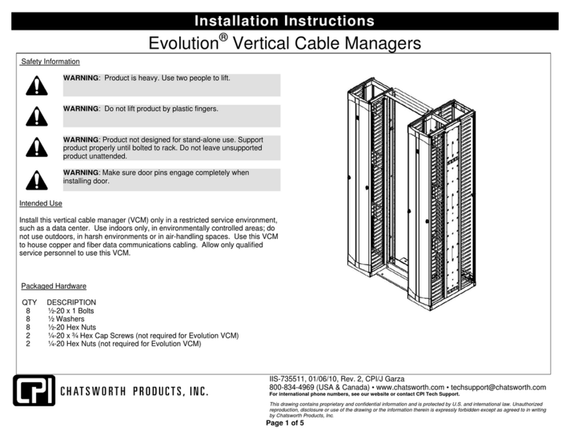
The Fiber Segregation Kit is for use with the Evolution™Vertical Cable Managers
in the following configurations:
The number of kits per manager depends on the position of the Movable Mid-
Section in Evolution g2 double-sided managers and the width of the vertical cable
manager as listed in the table below:
Cable
Manager
Width
Single-Sided or
Double-Sided with
50/50 Front/Rear Split
Double-Sided with
60/40 Front/Rear
Split
6” (150 mm) 0 1
10” (250 mm) 1 2
12” (300 mm) 2 2
Verify Mid-Section Locations
In order for the Fiber Segregation Kit to mount to the Accessory Panel on the
Single Sided Evolution g1 or the Moveable Mid-Section on the Double Sided
Evolution g2, the distance between the panels must be 18.6 inches.
Fiber Segregation Kit
18.6”

FIBER SEGREGATION KIT
Page 2 of 3
Installation Instructions
Tools Required
#3 Phillips Screw Driver
Intended Use
The Fiber Segregation Kit creates a separate pathway for fiber cables and patch
cords inside Evolution™Vertical Cable Managers.
Included Hardware
•Qty 5 ea – Taptite Screws, 10-32 x 1/2”
•Qty 2 ea – Fiber Segregation Spool Assembly
•Qty 2 ea – Extension Panel
Packaged Hardware
Fiber Se
g
re
g
ation S
p
ool Assembl
y
** Extension Panel
** The Extension Panel is required when mounting to the Single
Sided Evolution g1 or Double Sided Evolution g2 with Moveable
Mid-Sections in the center position.
10-32 x ½” Ta
p
tite Screw

FIBER SEGREGATION KIT
Page 3 of 3
Installation Instructions
Fastening Fiber Segregation Kit
NOTE: For easier installation, attach Fiber Segregation Kit before installing
optional Cable Spool Kit provided with Vertical Cable Manager.
Installation
1. Fiber Segregation Kits ship with all necessary hardware included.
2. Locate the included hardware to verify contents.
3. Mount a single assembly using two 10-32 x ½” screws.
4. For installing to a Double Sided Evolution g2 with Mid-Sections located in
the rear position:
a. Insert the 10-32 screws through the slots in the Fiber
Segregation Bracket closest to the indexing spool as shown in
Figure 1.
b. Attach the assembly using the second mounting holes in the Mid-
Section from the side panels as shown in Figure 1. Edge of
bracket should nearly touch side panel.
5. For installing to a Single Sided Evolution g1 or Double Sided Evolution g2
with Mid-Sections located in the center position:
a. Insert the 10-32 screws through the slots in the Extension Panel
as shown in Figure 2.
b. Attach the Extension Panel to the slots farthest away from the
indexing spool in the Fiber Segregation Assembly.
c. Attach the entire assembly using the second mounting holes in
the Mid-Section from the side panels as shown in Figure 2.
6. The Fiber Segregation Spools turn 360° with stops at 90° allowing easy
access to fiber cables.
FIGURE 1 FIGURE 2
10-32
Taptite
Screw
Extension Panel
Other Chatsworth Products Cable Box manuals