Bodine CertaPath CSL25B2 User manual

SAVE THESE INSTRUCTIONS
THIS PRODUCT CONTAINS A RECHARGEABLE LITHIUM-ION BATTERY.
THE BATTERY MUST BE RECYCLED OR DISPOSED OF PROPERLY.
Li - ion
Self-Testing Emergency LED Driver
READ AND FOLLOW ALL SAFETY INSTRUCTIONS
! IMPORTANT SAFEGUARDS ! WHEN USING ELECTRICAL EQUIPMENT, BASIC
SAFETY PRECAUTIONS SHOULD ALWAYS BE
FOLLOWED, INCLUDING THE FOLLOWING:
1. This product is for use with an emergency LED lighting load and supplies 25W of output power*, with
a voltage of 20-54 VDC in emergency mode for a minimum of 90 minutes, in compliance with NFPA
101 and NEC 700.12.
2. Make sure all connections are in accordance with the National Electrical Code or Canadian Electrical Code
and any local regulations.
3. To reduce the risk of electric shock, disconnect both normal and emergency power supplies before servicing.
Follow the instructions in the OPERATIONS section to disable the output of this LED driver.
4. This emergency driver is suitable for both factory or field installation.
5. This product is suitable for use in damp locations where the ambient temperature is 10ºC minimum,
+50ºC maximum. Product is also suitable for installation in sealed and gasketed fixtures. Product is
not suitable for heated air outlets and wet or hazardous locations. Maximum allowable case temp is
60ºC. See unit label for Tc measurement location.
6. An unswitched AC power source is required (120-277 VAC, 50/60 Hz).
7. Do not install near gas or electric heaters.
8. Do not attempt to service the battery. A sealed, no-maintenance battery is used that is not field replaceable.
Contact the manufacturer for information on service.
9. The use of accessory equipment not recommended by the manufacturer may cause an unsafe condition.
10. Do not use this product for other than intended use.
11. Installation and servicing should be performed by qualified personnel.
12. Equipment should be mounted in locations and at heights where it will not be subjected to tampering by
unauthorized personnel.
13. For Canadian application the output terminals should be in compliance with the accessibility requirement of
the Canadian Electric Code.
14. This device complies with part 15 of the FCC Rules. Operation is subject to the following two
conditions: (1) this device may not cause harmful interference, and (2) this device must accept any
interference received, including interference that may cause undesired operation.
15. This product must be grounded. See the wiring diagrams for details.
* Initial output power after one minute into discharge.
Installation Instructions
Bodine © 2023 Signify Holding. All rights reserved.
Collierville, TN USA 38017 • Tech Support 888-263-4638 • www.bodine.com
442295720416
CSL25B2
06/19/23

2
1. Ensure the LED load’s rated power is greater than or equal to the power output of this emergency LED
driver. This is to ensure that this emergency product will not produce more power than the LED load can
handle, thus ensuring that the LED load will not be damaged when the system is in the emergency mode.
2. Verify that the forward voltage of the luminaire’s LED array is within the limits of this emergency LED
driver. The forward voltage of the LED array is commonly designated as Vf and should be found on the
luminaire markings, in the luminaire specifications, or imprinted directly on the LED arrays. If multiple LED
arrays are to be driven, verify that the total forward voltage is within the limits of this product. Using a
voltage meter, it may be possible to directly measure the voltage across the LED arrays when operating
from the AC driver.
3. Ensure the output current of the AC LED driver does not exceed 5.0 Amps for Class 2 emergency product
and 3.0 Amps for Class 1 emergency product (see table above).
4. Ensure there will be sufficient light output in the end application. Estimate the egress lighting illumination
levels by doing the following:
a. Find the efficacy of the LED load. This can be given by the luminaire manufacture. This number
will be given in lumens per watt (lm/w). It is the installer’s responsibility to validate the luminaire
manufacturer’s efficacy data. This can be accomplished by direct measurement, by review of
independent 3rd party test data (UL, ETL, etc.), accessing a public database of 3rd party data (such
as Design Lights Consortium, www.designlights.org), or other comparable means.
b. Lumens can be calculated by multiplying the output power of the emergency LED driver (see table
above) by the efficacy of the luminaire. In many cases the actual lumen output in emergency mode will
be greater than the results of this calculation, however it will provide a good estimate for beginning
the lighting design of the system.
Lumens In Emergency Mode = Lumens per Watt of Fixture * Output Power of Chosen Product
(Lumens) = (lm/W) * (W)
c. Using the results of this calculation and industry standard lighting design tools, calculate the
anticipated illumination levels in the path of egress.
This product is suitable for field installation with suitable LED loads including LED luminaires, DC voltage driven
LED replacements for fluorescent lamps and others. There are four (4) checks to determine if your luminaire is
eligible for field installation.
* Initial output power after one minute into discharge.
INSTALL ATION
STEP - 1 DETERMINE SUITABILITY
Installation of this emergency LED driver will vary based on the luminaire type, however, generally follow these
steps:
Make sure the necessary branch circuit wiring is available. An unswitched source of power is required. The
emergency driver must be fed from the same branch circuit as the AC driver.
NOTE: This product has been designed to reliably interface with a wide selection of LED loads and
is electrically compatible with every simple LED array that meets criteria 1 and 2 above. However,
compatibility cannot be guaranteed with all current and future LED systems. Compatibility testing of
the end-use system is recommended. Please contact the factory for more information.
NOTE: After installation, it will be necessary to measure the egress lighting illumination levels to
ensure they comply with national, state, and local code requirements.
3
OPERATION
STEP - 4 WIRING THE EMERGENCY DRIVER
> Select the appropriate wiring diagram to connect the emergency driver to the AC driver and LED
load. Make sure all connections are in accordance with the National Electrical Code and any local
regulations.
> After installation is complete, supply AC power to the emergency driver.
> At this point, power should be connected to both the AC driver and the emergency driver, and the
Charging Indicator Light should illuminate indicating the battery is charging.
> A short-term discharge test may be conducted after the emergency driver has been charged for
one hour. Charge for 24 hours before conducting a long-term discharge test. Refer to OPERATION.
> In a readily visible location, attach the label "CAUTION - This Unit Has More Than One Power
Connection Point. To Reduce The Risk Of Electric Shock, Disconnect Both The Branch Circuit-
Breakers Or Fuses And Emergency Power Supplies Before Servicing."
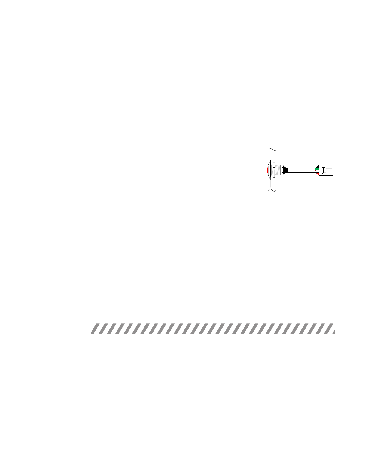
STEP - 3 INSTALLING THE ILLUMINATED TEST SWITCH
> Mount the supplied Illuminated test switch in a location that is
visible and accessible by maintenance personnel. The test switch
mounts through a ½” hole which may need to be made in the
luminaire or could come pre-punched by the luminaire supplier.
> Connect the test switch by connecting it to the unit test switch
cable.
> If connected correctly, the indicator light should be ON when
AC power is supplied to the fixture indicating that the unit is
charging. After installing, mark with the "PUSH TO TEST" and
"CHARGING INDICATOR LIGHT" labels.
> Disconnect AC power from the LED luminaire.
> Mount the emergency LED driver by the mounting tabs using the supplied screws. The
luminaire’s installation instructions may provide guidance on the recommended mounting
location.
>Mounting Height: Many factors influence emergency illumination levels, such as the lamp
load selected, luminare design, and environmental factors therefore end use verification is
necessary. For field installations, when the attached luminaire is mounted at heights greater
than 7.17ft (2.2m), the level of illumination must be measured in the end application to ensure
the requirements of NFPA 101 and local codes are satisfied.
>Remote Mounting: The emergency LED driver may be remote mounted from the luminaire if
installed in accordance with the NEC. If used in conjunction with an AC driver the allowed
distance is up to half the distance the AC driver manufacturer recommends remote mounting
the AC driver from the LED load. If used without an AC driver, and remote mounting more than
5 feet from the luminaire, please consult the factory to determine the necessary wire gauge.
CAUTION: Remote mounting can result in reduced power output.
STEP - 2 INSTALLING THE EMERGENCY DRIVER
ILLUMINATED TEST
SWITCH
Fixture
When AC power fails, the emergency driver automatically switches to emergency mode, powering
the LED load per the rating of the emergency driver for a minimum of 90 minutes. When AC power is
restored, the emergency driver returns to charging mode.
ABConnect:
Applying AC power to the unit activates the charger circuit, and supplies power to the control/monitor
circuit and charging indicator light.
To deactivate the unit for storage or shipping, press and hold the test button while the unit is in
emergency mode until the LED load is turned off.

4
TROUBLESHOOTING GUIDE
NOTE: For short-term testing of the emergency function, the battery must be charged for at least one
hour. The emergency driver must be charged for at least 24 hours before conducting a long-term test.
If the unit has encountered a problem after installation, then it will flash the error code with the indicator light. Count
the number of times the indicator is OFF to read the number of flashes. Then use the troubleshooting steps to solve the
issue.
MAINTENANCE
This self testing emergency driver automatically performs required routine testing. Results are
reported to maintenance personnel via the indicator light.
Note:
Maintenance personnel should periodically check the indicator light per Life Safety Code requirements
(NFPA 101). If the indicator light is flashing, follow steps in the following Troubleshooting Guide.
INDICATOR
LIGHT STATE ERROR CORRECTIVE ACTION
0x Flashes
Light On Steady None
No Action. The Unit is Operating Correctly.
2x Flashes Battery
Indicates that a self-test/self-diagnostic test did not meet full duration.
1. Charge the unit for the rated recharge time and perform a manual self-diagnostic test.
2. If error is still present then the product is past end of life and should be replaced.
3x Flashes Charging
1. Check input AC mains wiring of Unswitched Hot, Neutral, and Ground.
2. Verify Voltage and Frequency are stable and match the product’s input ratings on the label.
4x Flashes Commissioning
During a self-test/self-diagnostic test, the unit detected the LED load has changed of more than 25%
from the initial commissioned value.
1. Replace the LED Load and perform a manual self-diagnostic test.
2. If error is still present but the LED load is functioning properly, then recalibrate the commission
value by deactivating the unit. Apply AC mains to activate unit and it will recommission itself after
one hour.
5x Flashes Temperature
Product temperature is beyond its rated temperature range.
1. Ensure unit is within the rated temperature range stated on the product label.
2. Confirm by measuring at the Tc point on the product label.
Continuous Flashing LED Load
Indicates a problem with the connected emergency LED load.
1. Check output wiring to the LED Load and verify polarity is correct.
2. Check for Open or Short circuit on the output connections.
3. Check Vf is within the rated output voltage range in emergency mode.
4. Ensure LED load is operational and specified for unit.
Self-Test:
This unit contains a control/monitor circuit that if enabled automatically performs a 30-second discharge
test once a month and a full 90-minute discharge test once a year. During routine testing, the self-testing
emergency driver simulates an AC power failure causing the unit to automatically switch to emergency
mode. The unit will monitor the operation of the LED load, battery voltage, and emergency duration. If the
emergency system functions properly, then the unit will return to normal mode. Should the unit detect any
problems, the indicator light will flash per failure condition (see Troubleshooting Guide) until the condition
has been corrected and the unit passes the next test.
Commissioning: After the emergency driver has been charged for one-hour an automatic
commissioning test will be performed. The emergency driver will switch to the emergency mode for 30
seconds and store in its memory the current level of the connected load. If, during future self-test,
this level deviates by more than 25%, an error will be triggered.
Caution:Once commissioned, connecting this equipment to higher voltage loads will result in reduce
current levels triggering the derangement signal indicating the equipment requires re-calibration to ensure
proper operation.
To reset a failure indication, briefly push the Test Switch. If the condition has not been corrected by the
next scheduled test, the unit will once again detect the failure and signal the failure indicator.
To perform a manual self-diagnostic test, push and hold the Test Switch for minimum of 5 seconds. Once
test switch is released the emergency driver will perform a 30 second diagnostic test. During this test, unit
will monitor the operation of the LED load, and battery voltage. If the emergency system functions properly,
the unit will return to normal mode. Should the unit detect any problems, the indicator light will flash per
failure condition (see Troubleshooting Guide) until the condition has been corrected and the unit passes
the next test.
5
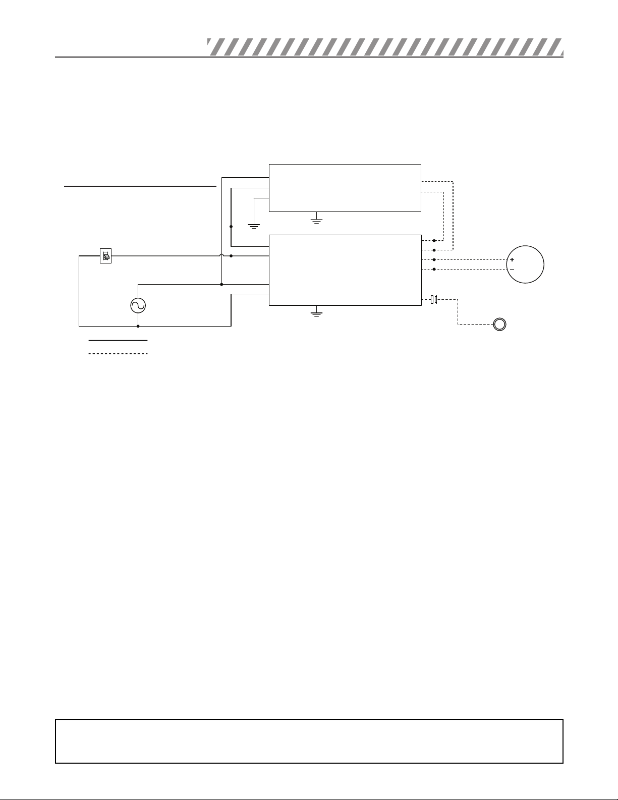
EMERGENCY DRIVER AND AC DRIVER MUST BE FED FROM THE SAME BRANCH CIRCUIT
TYPICAL SCHEMATICS ONLY. CONSULT THE FACTORY FOR OTHER WIRING DIAGRAMS.
WIRING DIAGRAMS
NOTE: For short-term testing of the emergency function, the battery must be charged for at least one
hour. The emergency driver must be charged for at least 24 hours before conducting a long-term test.
Unswitched Line
White/Black
White/Red
Black
White
Neutral
Line
Ground
LED+
LED−
Yellow/Black
Yellow/Black
Yellow
Blue
Switched Line
Neutral
Wall
Switch
Switched Line
UL Class 1 circuits
UL Class 2 circuits
Illuminated
Test Switch
Emergency
Driver
LED Driver
Max Current = 5.0A
LED
LOAD
AC Mains
120/277Vac
50/60Hz
For Class 2 Emergency
Driver Internal Battery
Table of contents
Other Bodine DC Drive manuals


Popular DC Drive manuals by other brands


Baumuller
Baumuller b maxx BM4400 Compact manual

Afag
Afag BF10 Translation of original operating instructions

Pentek
Pentek INTELLIDRIVE PID10 owner's manual

Danfoss
Danfoss VLT OneGearDrive operating instructions

Ci Design
Ci Design iStoragePro Dock II quick start guide

Toshiba
Toshiba T300MV2 instruction manual