Bodor BCL-X series User manual
User Manual for BCL-X Series Laser Machine
1
Laser Engraving and Cutting Machine
User Manual for BCL-X
Series
Jinan Bodor CNC Machine Co., Ltd
Adress: Huaya Industrial Park, Kanghong Road, High-Tech Zone, Jinan,
Shandong, China
ZIP: 250101
TEL: 0086-531-88690020
FAX: 0086-531-88690199
After-sales service:0086-531-88270377
Website:www.bodorcnc.com

User Manual for BCL-X Series Laser Machine
2
Brief Introduction of Laser Engraving Cutting Machine.................................................... 4
I Safety Knowledge..................................................................................................... 4
1.1 Basic Information.................................................................................................. 4
1.2 Optical Security............................................................................................. 4
1.3 Electricity Security........................................................................................ 4
II Equipment Brief Introduction............................................................................... 5
2.1 Instruction of Machine Model&Nameplate...................................................5
1. Model Instruction............................................................................................ 5
............................................................................................................................. 5
............................................................................................................................. 5
2. Nameplate Instruction......................................................................................6
2.2 Equipment Composition................................................................................ 6
2.3 Power Strip.................................................................................................. 15
III Equipment Installation..........................................................................................16
3.1 Installation Preparation................................................................................16
3.2 Installation procedure.................................................................................. 16
3.3 Grounding Connection................................................................................ 20
IV Test Equipment.....................................................................................................20
4.1 Inspect before powering on......................................................................... 20
4.2 Adjust light path...........................................................................................21
V Rotation axis processing........................................................................................ 28
VI Simple operation instruction................................................................................ 36
6.1 Software installation.................................................................................... 36
6.2 Data line using operation.............................................................................38
6.3 U disk operation...........................................................................................49
VII Equipment's maintenance....................................................................................52
7.1 Daily maintenance....................................................................................... 52
7.2 Water tank’s change and clean.....................................................................52
7.3 Exhaust fan’s clean...................................................................................... 52
7.4 Reflector’s and lens’ clean...........................................................................52
7.5 Guide rail's clean......................................................................................... 53
7.6 Light path's examination..............................................................................53
VIII CO2 glass laser tube's precautions for use.........................................................53
IX Common Breakdown Maintenance...................................................................... 54
Appendix 1................................................................................................................ 56
《After-sale warranty of Laser Engraving Cutting Machine》........................ 56
Appendix 2................................................................................................................ 59
Cutting and engraving parameters of laser tubes...............................................59
Postscript................................................................................................................... 62
《After-sale warranty of Laser Engraving Cutting Machines》.......................................62

User Manual for BCL-X Series Laser Machine
3
Preface
Thank you very much for your trust and purchasing our Products. We can provide perfect
after-sale service and solutions. Please keep this manual and other attachments carefully,
in order to guarantee the equipments safe running.
This manual is only applied to our company’s standard machines. With regard to special
customized machines, please read other reference material carefully.
This manual is written to demonstrate the issues about working principle, installation,
operation, failure removal, transport,storage, maintenance etc. Please read the manual
carefully, if you use the equipment the first time.
For quick and efficient using this equipment, the user should have qualifications as
below:
1. The user needs to know basic computer professional knowledge, and can operate
related editing and drawing software, such as Coreldraw, Photoshop, Autocad and so on.
2. The user should have basic optical knowledge and related electromechanical device's
maintenance knowledge.
3. Before starting the equipment, make sure this equipment's operation procedure is
known well and operate accordingly.
Because of equipments continuous updates, there may be some difference between your
equipments and equipments shown in the manual in some aspects. We apologize for the
convenience.
If you have any good suggestions or doubts, please log in our website
www.bodorcnc.com to leave a message or call us directly.
After-sales' Service:0086-531-88270377

User Manual for BCL-X Series Laser Machine
4
Brief Introduction of Laser Engraving Cutting
Machine
ISafety Knowledge
1.1 Basic Information
Make sure that the operator is being trained before operating the machine.
Operator must be aside the machine during machine working. Never leave the
machine alone in case to cause unnecessary loss.
1.2 Optical Security
Our laser equipment adopts the forth laser tube.Length of laser beam is 10.6μm. During
machine working, we recommend people related to wear authorized laser safety goggles.
Do not stare at the laser beam or anything beam reflected.
1.3 Electricity Security
Before connecting electricity, please check carefully the requirements on the
equipment's name plate, such as power,working voltage and so on.
Without our permission, please don't dismantle electrical apparatus elements on the
equipment, especially do not touch laser power and laer tube during machine
working. Because the equipment has fatal voltage when working, and danger can
still exist after disconnecting electricity.
1 Harm
Various potentially dangerous substance can be eliminated through ventilation system
during plastic material cutting. If smog or smell is too heavy, gas mask is needed.
2 Other Harm
Out of security consideration, equipment modification is forbidden without the
permission from the Manufacturer.
User Manual for BCL-X Series Laser Machine
5
II Equipment Brief Introduction
2.1 Instruction of Machine Model&Nameplate
1.Model Instruction
※※※一※※※※一※※
BCL1309X means standard serial laser cutting machines with 1300mm x 900mm
working area and up-down working table.
Machine Serial
BCL:
Bodor Cutting
Laser
BML:
Bodor Marking
Laser
Machine Working Area:
0503: 500mm×300mm
0605:600mm ×500mm
1006:1000mm×600mm
1309: 1300mm×900mm
1610: 1600mm×1000mm
… ……
Model Introduction:
M: Mini Machine Serial
X: Standard Machine Serial
B: Bed Machine Serial
FB: Fiber Laser Cutting
Machine Serial
YB/YT: High Power Metal
Cutting Machine Serial
FP/BM: Fiber Laser Marking
Machine Serial
Other Attachments:
U- with up-down working
table
F- automatic focus/fiber
generator
H- high speed guid rail
V- vac-sorb
A- auto feed
CCD- automatic logo
positioning cutting machine
P- separable style stone
engraving machine
S- screw machine
R-RF tube
G-glass engraving machine
D-die board cutting machine

User Manual for BCL-X Series Laser Machine
6
2.Nameplate Instruction
This serial equipment is vertically installed in the middle of the transmission shaft, which
can make speedy and stable cutting and engraving.The nameplate of machine is in the
right-back side. You can read the relevant information on it. It is not accepted for
anybody to change or remove this nameplate.
2.2 Equipment Composition
Declaration: Due to different models or new updates in products, there may be some
difference in appearance or some partial detail. Specific equipment is subject to
final product.
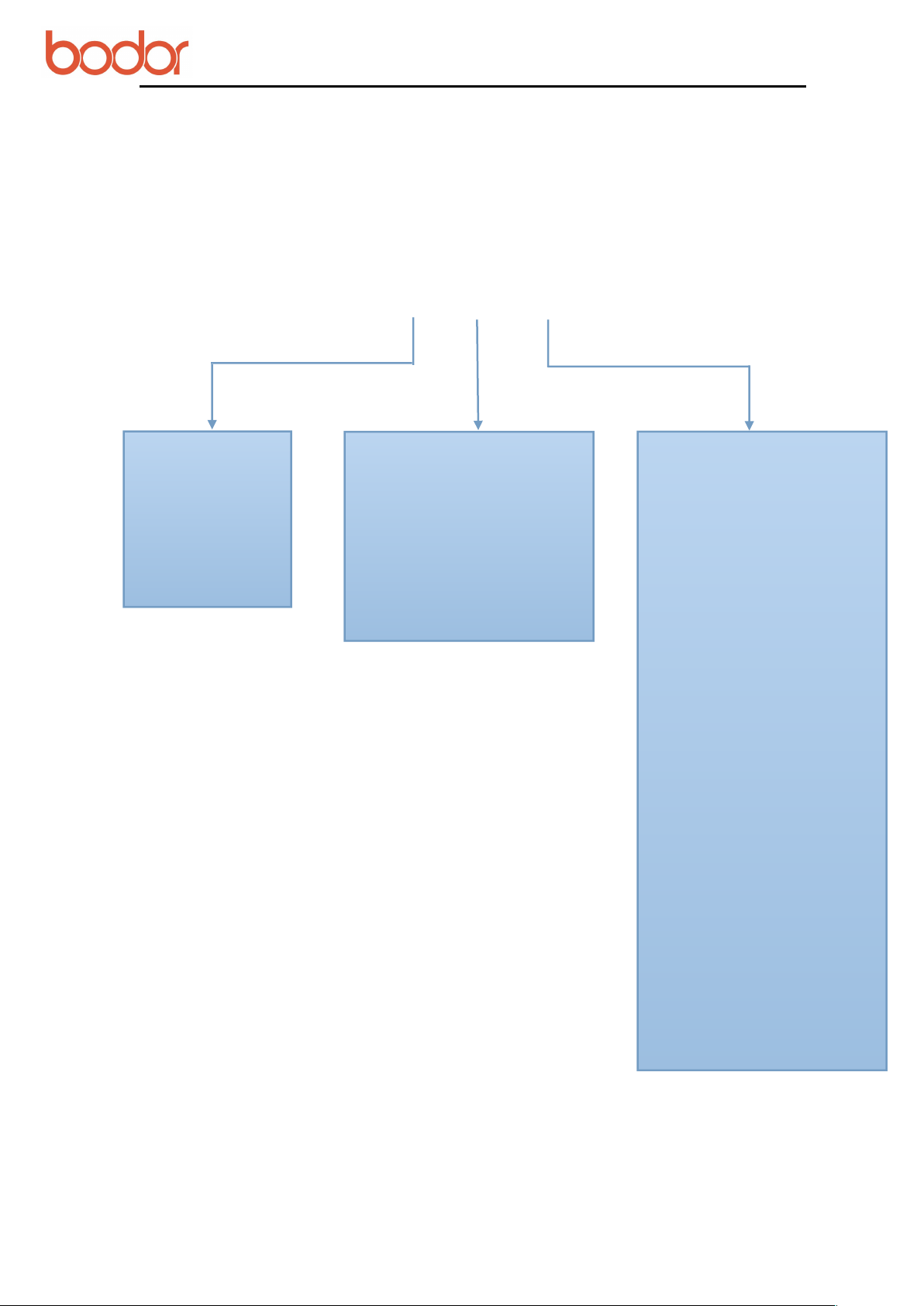
2.2.1 Composition of full set machine
A.Machine Shell B.Drive System C.Optical System D.Control System E.Spare Parts F. Tool
Box
Laser
Machine
Machine
Shell
Drive
System
Optical
System
Control
System
Spare
Parts
Tool
Box
This number is only for each machine
User Manual for BCL-X Series Laser Machine
7
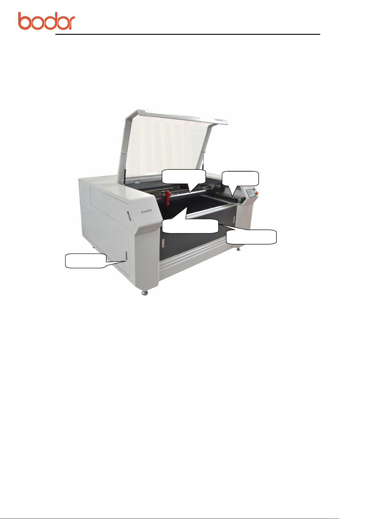
2.2.2 Machine Shell
Right/Left Shield; Side Door; Up Cover; Transom(X Axis); Carling (Y Axis);
Working Table.
Working
Side
Front Door
Transom
Carling

User Manual for BCL-X Series Laser Machine
8
2.2.3 Drive System:
Y Axis:
Back
Smoke
Entrance
Name
Universal
Wheel
Foot
USB Flash Interface
Computer Interface

User Manual for BCL-X Series Laser Machine
9
X Axis:
Guide Rail
Girdle
48 tooth
Synchronizin
g Wheel
Motor
Transmissio
n
24 tooth
Synchronizing Wheel
belt
Guide Rail
Belt
Mot
or
Pinion Stand
Endless-belt
Couple
r
24 tooth
Synchronizing
Wheel
48 tooth Synchronizing
Wheel

User Manual for BCL-X Series Laser Machine
10
2.2.4 Optical System
Attention:
The laser tube is fragile. It should be taken slightly. Water inlet of the laser tube should be
in the lower place, and water outlet be in the higher place(reci laser tube), so there won't
be any bubble. The laser tube socket should be installed with even force which can just
make the tube secure. Do not overexert, it may crush the laser tube.
Attention:
The front surface of reflection mirror should be faced to the laser outlet.
Laser Tube
Reflection Mirror
Laser outlet
Cathode rays
Reflection Mirror frame
Laser Tube Socket

User Manual for BCL-X Series Laser Machine
11
Attention:
The working-voltage of high-tension cable can be higher than 100,000V.There can be
strong static electricity even when the power was cut-off in short time. Please do not
touch the cable directly.
Installation picture of RECI laser tube
Attention:
Before working, please adjust the focal length. Put the focal length in the middle of
working material and laser outlet before working. Convex surface should be faced to working
material when installing focus lens.
High-tension cable
High-voltage insulation protective jacket
Water-in
Water flow direction
Red dot position
Air compressor
control valve
Focus Lens
3rd Reflection
Mirror
Focal length adjusting
tool
User Manual for BCL-X Series Laser Machine
12
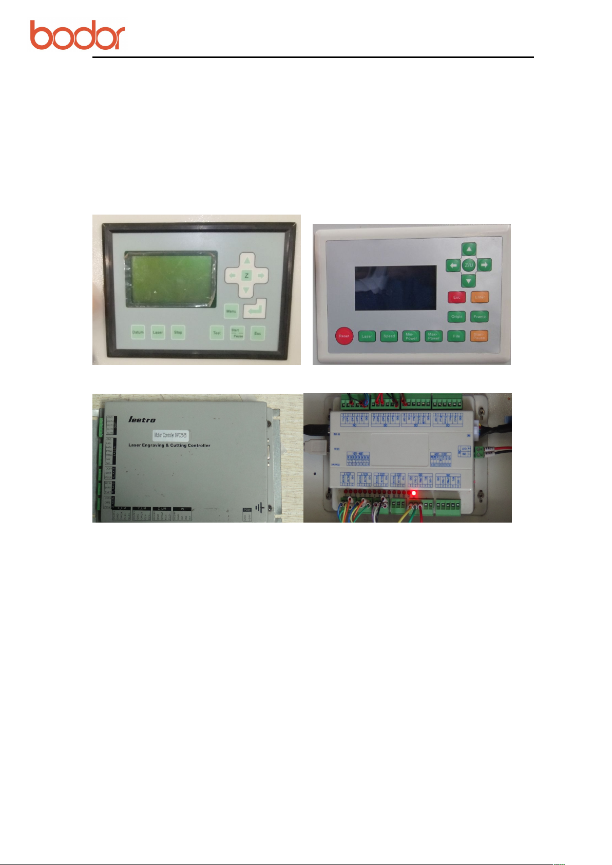
2.2.5 Control System
There are some difference in the control system for different models.Specific product is
subject to real object.
Bodor's control system is as below:
Leetro control system;
Ruida control system;
Bodor control system.
Leetro control panel Ruida control panle
Leetro control board Ruida Control Board

User Manual for BCL-X Series Laser Machine
13
2.2.6 Spare parts
Water Chiller Exhaust fun Air compressor
Filter
48V Switch power
X Axis Motor Drive
Y Axis Motor Drive
Z Axis Motor Drive
System card board
Relay
DC24V and 5V
Power
Laser
Power
Emergency
Switch
Ammeter
Potentiometer
Start Button

User Manual for BCL-X Series Laser Machine
14
2.2.7 Tool Box
Attention: There can be some difference in toolbox for different models. Specific parts
are subject to real objects.
Proximity Switch&Inching Switch
Shovel Blade Usage Focus Block Usage
Certificate
Approval
Data
Power
Limit Swith
Double-sided
Adhesive Tape
High-tension
Adhesive
Tape
U Disk
CD
Water/Air Tube
Fork
Wrench
Hexwrenc
Shove
l
Focus
Block
Dimming
Block
User Manual for BCL-X Series Laser Machine
15
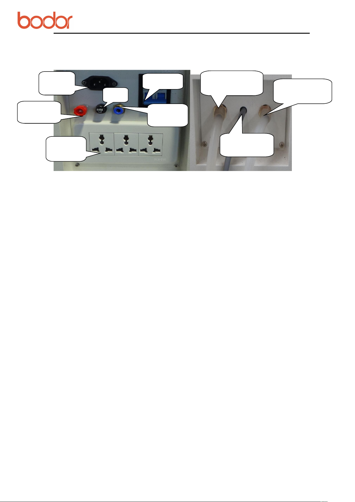
2.3 Power Strip
Air Switch
Power
Interface
Abalone
Socket
Ground
Line
Air-tube
Interface
Fuse
Water Chiller
Signal Line
Outlet Connecting
Water Chiller
Inlet Connecting
Water Chiller

User Manual for BCL-X Series Laser Machine
16
III Equipment Installation
3.1 Installation Preparation
3.1.1 Preparation for workplace
Make sure the working area is dry enough. And any electromagnetism, strong power,
pollution is forbidden. Temperature of working environment should be 10℃to 38℃,
humidity should be 10- 90%. AC 220V±10%, 50HZ, resistance to ground less than 5Ω.
3.1.2 Preparation for operator
We demand the operator must be professional technician. If the users want to install the
equipment on their own, they need to have training from our technicians and completely
master the knowledge of installation.
3.1.3 Preparation for tools
There is already a tool box with this machine. Besides, multimeter and screwdriver and
other detection tools are needed.
3.1.4 Other preparation
The users need to prepare relevant material,including purified water or distilled water for
water chiller, power strip, computer,pipe for discharge smoke, sample material, etc.
Attention: The users need to accompany all the time when our technicians install the
equipment. The users need to grasp the skills of installation and commissioning which
are the part of training.
3.2 Installation procedure
3.2.1 Package of laser tube
Laer tube package:
In case of damage during transportation or outside force, the tube is packed with sponge.
And two ends of tube are sealed with zip lock bag to prevent the mirror from pollution or
scratch. Finally, the tube is built up with sponge supports to prevent tube have direct
contact with surrounding.

User Manual for BCL-X Series Laser Machine
17
Laser tube devanning:
Open the carton box, take out the laser tube. Both hands hold the middle of the tube; take
off the sponge supports; take off the packing sponge; take off the zip lock bag. Then
inspect whether the tube is intact.
Attention: It needs as least two persons when unboxing. Handle the tube with care.
3.2.2 Installation of Laser tube
Move the equipment to the back place, so as to install the laser tube easily.
The laser tube is installed in the back of crossbeam.Open the laser tube protective cover.
You can see two laser supports, two water pipes, a black color low-tension line and a red
color high-tension line.
Low-tension line High-tension line
Laser tube installation:
1.Take off the screw from the two laser support which are used for fitting the laser tube.
2.Put the outlet(low-tension part) of the laser tube on the base facing to the first reflected
mirror.
3.Buckle the upper part of the laser tube support, tighten the screw, connect the
high-tension&low-tension line and outlet&inlet water tube.
4.Fix the laser tube.
Attention:
Keep the laser tube outlet clear in case of front mirror breakdown. The broken
damage caused by improper operation, will not be in Bodor's range of protection.
Fix the laser tube with proper strength. Larger strength will broke the laser tube.
Keep the laser tube water inlet in the lower place, and the water outlet in
the higher place(in the upper section of laser tube). Come in from the bottom, out
from the top as shown in the above picture.
Water tube joints must be connect well avoiding water leaking. Water tube must be
straightened.
Handle laser tube carefully when installing.High-tension wire and cathode rays
should be fastened enough.Water inlet should be in the bottom and water outlet in the
top. Make sure there is no air bubble in the laser tube. Use even force on the two
sides when pushing laser tube sockets to fix the laser tube. Do not use too much
force avoiding the damage of laser tube.

User Manual for BCL-X Series Laser Machine
18
3.2.3 Installation of Water Chiller
▲ First take down the cover of water inlet on the top of the chiller. Pour purified water or
distilled water into the water tank until it is full.
▲ Then complete the connection of water cycle pipelin by connecting the water outlet of
the chiller with the water inlet of the machine, and the water inlet of it with the water
outlet of the machine.
▲ Finally, connect the holding wire and the water chiller power line.
Pressing the rocker switch after electrifying the chiller, you can hear sound like
"didi...".Then the water in the tube will flow from high-tension terminal to low-tension
terminal. Then the green indicator light on water chiller will be on. The system works
well if the alarm does not ring.
Attention:
When working, the water must flow from the high-tension to the low-tension.
Otherwise, it may damage the laser tube.
When the power is on, the bubble in the tube can be removed by extruding the water
pipe or turning the laser tube.
When machine is working or shut down, please do not touch the high-tension line. It
may still have high power and may threat to life.
Chiller installation: water-inlet in the top side, water-outlet under the back below side
3.2.4 Installation of Exhaust Fan and Air Pump
Installation of Exhaust Fun
Connect the air inlet of the fan with exhaust port by the air duct and screw tightly with
spanner. Then connect the outlet of the fan by the other air duct and lead it out of the
room. The installation is as shown in the below.
display
Water inlet
green indicator
light
Water-outlet
Water-in
Alarm
Power line
Ship type switch
Water-out
Alarming line

User Manual for BCL-X Series Laser Machine
19
Installation of Air Pump
Insert the silicone tube into the air-inlet by an air tube. Then connect the power and make the smooth
air-out of the air entry in the leaser head as shown in the below picture.
Air pump (air compressor) is very important in the system. High-pressure air sprays from
the light outlet of laser head through air tube. On one hand, it can keep the focus lens
clear enough. On the other hand, it can prevent working material from burning. Please
make sure the rubber tube is intact during machine working. Otherwise it may cause
burning of the materials.
Screw tightly
with spanner
User Manual for BCL-X Series Laser Machine
20
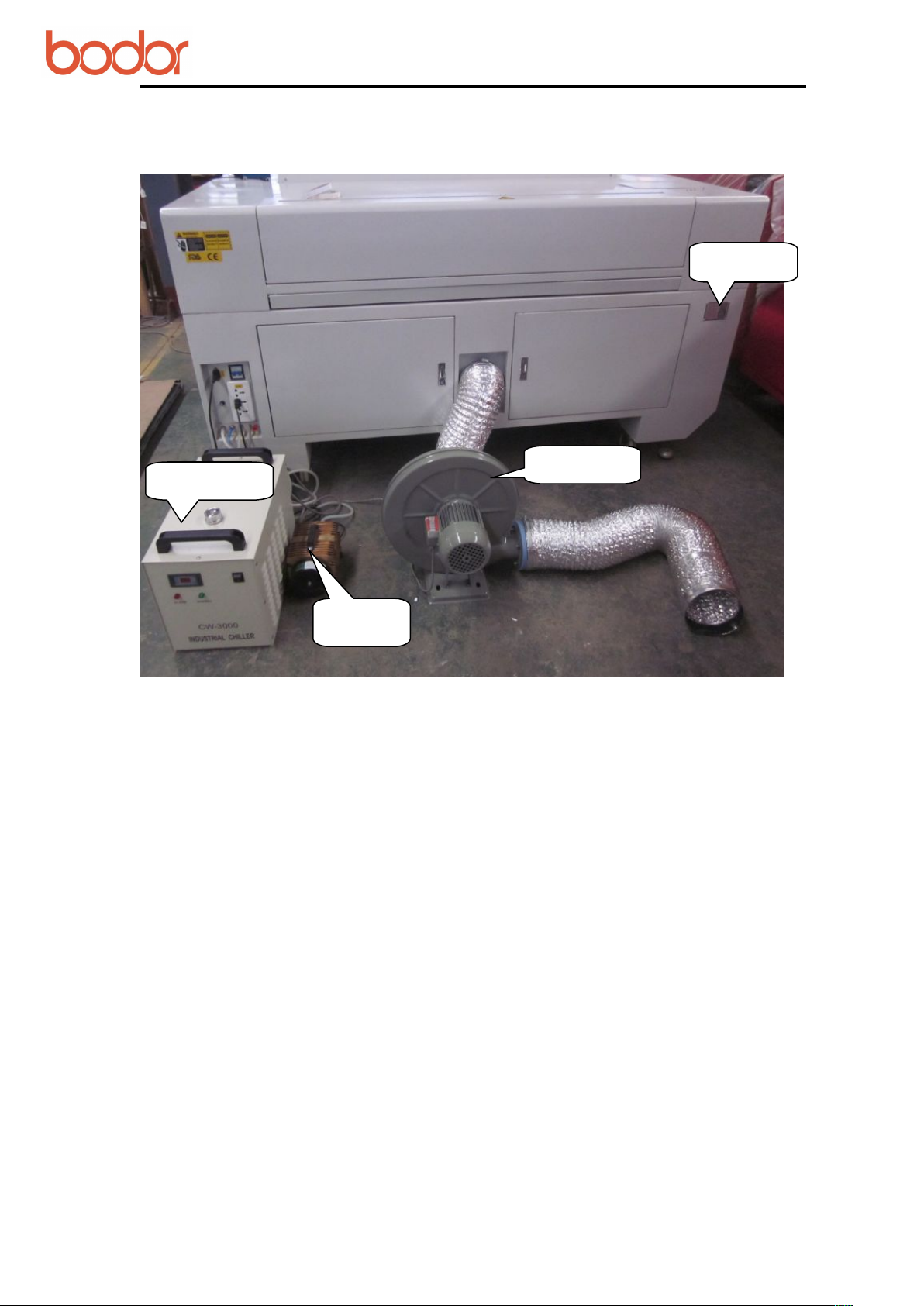
3.2.5 Installation of accessory
3.3 Grounding Connection
Grounding requirements for the equipment are very strict. Your local electric system
must meet the local electric security standard.
L : 220V Live line; Phase line
N : Zero Line, compose the electric system together with phase line
E: Grounding line, connect every grounding part of electricity consuming
accessories,resistance to ground should be less than 4 Ω
Attention:
Nonstandard grounding may lead to high failure rate and other security accidents. All
these are not in the range of Bodor's protection.
IV Test Equipment
4.1 Inspect before powering on
Before powering on, please inspect and make sure all electric wire terminals are intact.
Name Plate
Water Chiller
Air pump
Exhaust Fun
Table of contents
Other Bodor Cutter manuals


