Bushranger MT261 Owner's manual

MT261
(Multi-Cutter Power Unit)
MC-PX/PS/PL
(Pruner Attachment)
MC-S
(Straight Shaft Attachment)
MC-HT
(Hedge Trimmer Attachment)
MC-HTS
(HedgeTrimmerAttachment)
MC-E
(Edger Attachment) MC-T
(Cultivator Attachment)
Owner’s/ Operator’s Manual
Completely read and understand this manual before using this product.

_1 _
Foreword
This Owner’s/ Operator’s Manual is designed to familiarize the operator with the various features and com-
ponent parts of the equipment and to assist you with the assembly, operation and maintenance of your new
Multi-cutter.
It is essential that any operator of this Multi-cutter reads and understands the contents this manual before
using the Multi-cutter.
For additional assistance, contact any local authorized BUSHRANGER dealer.
Important Notice
The benets to the consumer given by this warranty are in addition to other rights and remedies of the con-
sumer under a law in relation to the goods or services to which this warranty relates. Our goods come with
guarantees that cannot be excluded under the Australian consumer law. You are entitled to a replacement
or refund for a major failure and for compensation for any reasonable foreseeable loss or damage. You are
also entitled to have the goods repaired or replaced if the goods fail to be of acceptable quality and the
failure does not amount to a major failure.
Contents
Page
Foreword ......................................................... 1
Contents .......................................................... 1
Safety Instructions........................................... 2
Operator safety............................................ 2
Multi-cutter safety ........................................ 2
Fuel safety ................................................... 3
Multi-cutter Operating Safety....................... 3
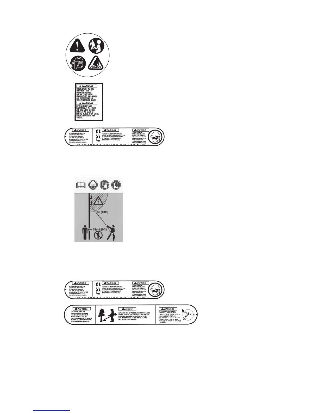
Safety and Instruction Decals ..................... 4
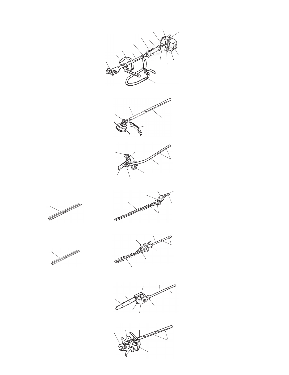
Product Description… ..................................... 6
Assembly......................................................... 7
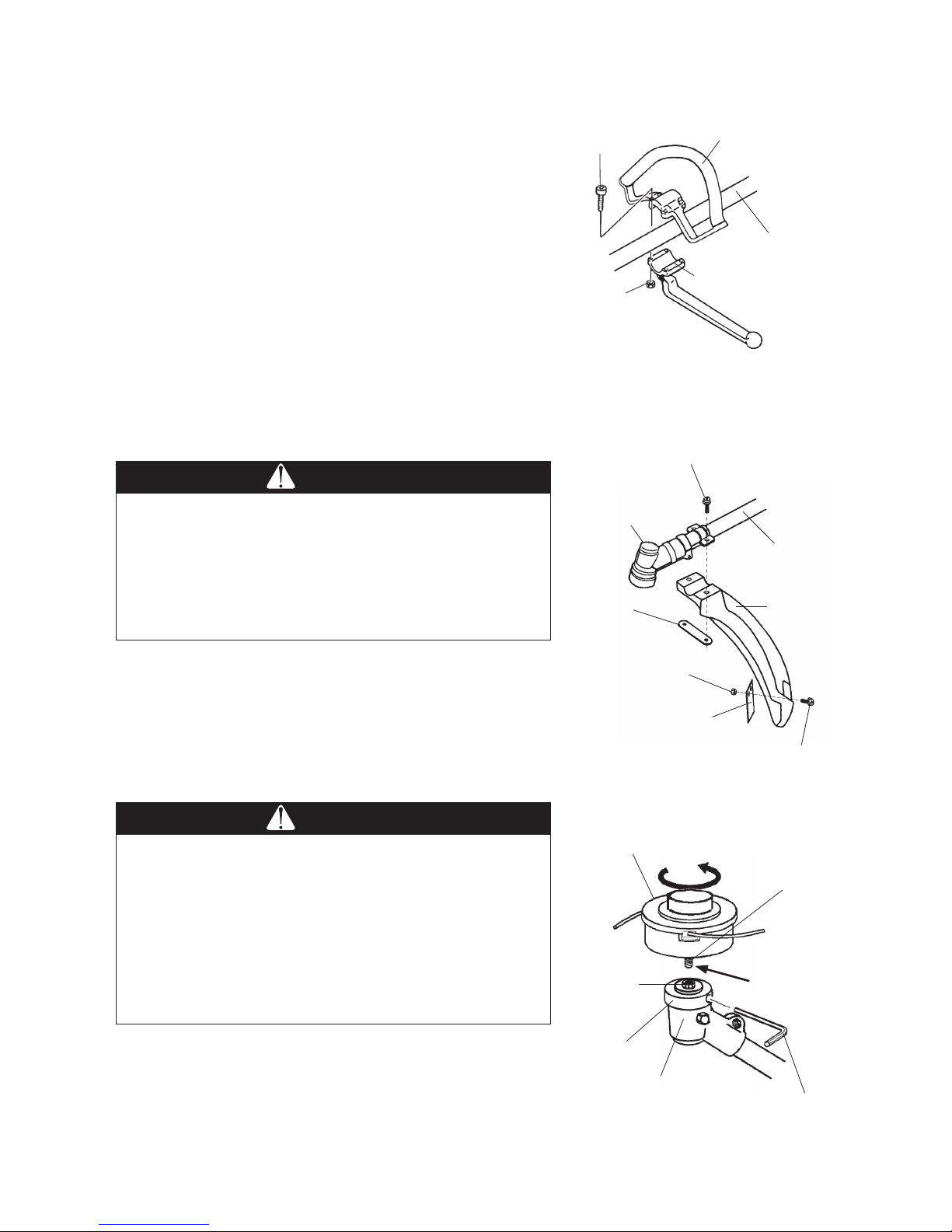
Loop Handle Installation ............................ 7
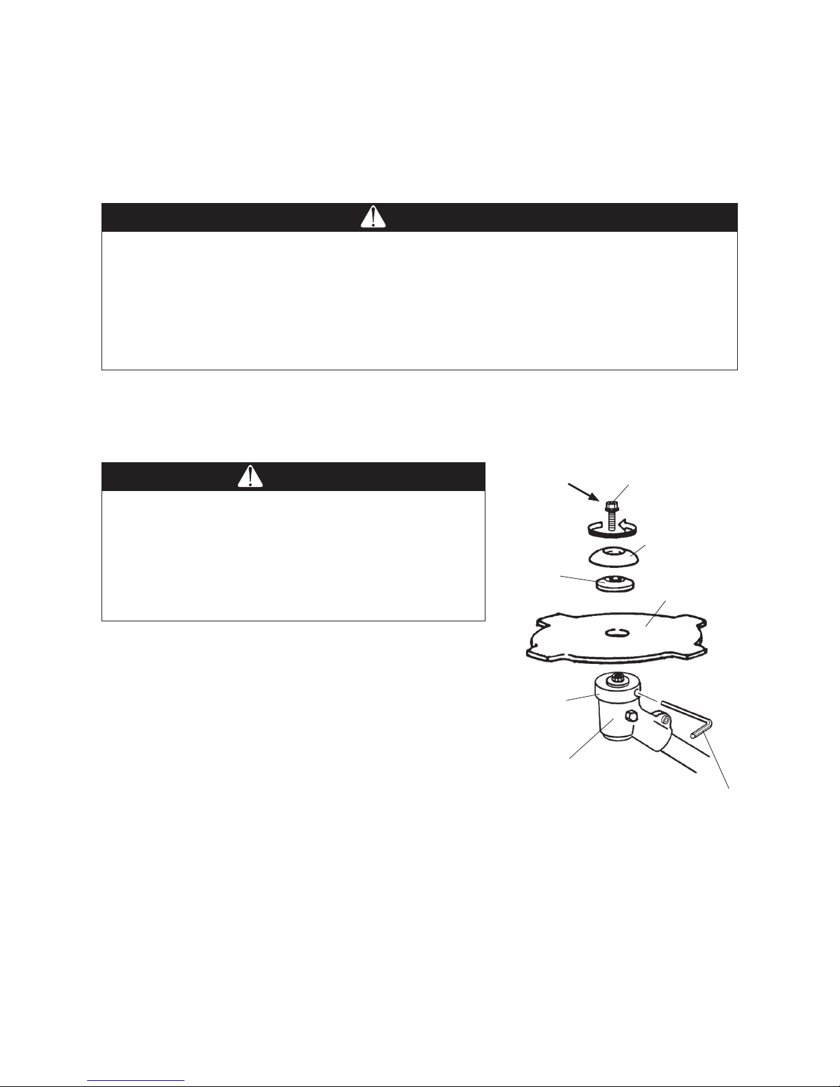
MC-S (Straight Shaft Attachment) .............. 7
MC-E (Edger Attachment) ......................... 9
MC-HTS(Hedge Trimmer Attachment) ....... 9
MC-PX/PS/PL (Pruner Attachment) ......... 10
MC-T (Cultivator Attachment) .................. 11
Attaching Shoulder Strap.......................... 12
Connecting the Tool Attachment
to the Power Unit ..... 12
Before Operation ........................................... 13
Chain Oil (Pruner Attachment).................. 13
Engine Oil and Fuel ………………………..14
Mixing Petrol and Oil................................. 15
Starting and Stopping ............................... 16
Idle Speed Adjustment.............................. 17
Page
Operation ...................................................... 18
MC-S (Straight Shaft Attachment) ............ 18
MC-E (Edger Attachment) ....................... 21
MC-HT/MC-HTS
(Hedge Trimmer Attachment) ............... 22
MC-PX/PS/PL (Pruner Attachment) ......... 24
MC-T (Cultivator Attachment) .................. 26
Maintenance ................................................. 27
Air Filter ................................................... 27
Fuel Filter.................................................. 27
Spark Plug ............................................... 28
Cylinder Cooling Fins................................ 28
Spark Arrester .......................................... 28
MC-S (Straight Shaft Attachment) ............ 29
MC-E (Edger Attachment) ....................... 29
MC-HT/MC-HTS
(Hedge Trimmer Attachment) ............... 30
MC-PX/PS/PL (Pruner Attachment) ......... 31
MC-T (Cultivator Attachment) ................... 33
General Cleaning and Tightening ................. 33
Storage.......................................................... 33
Troubleshooting............................................. 34
Specifications ................................................ 34

_2 _
Operator safety
1. Read and understand this Manual before using the Multi-cutter.
Be thoroughly familiar with the proper use of this Multi-cutter.
2. Always wear eye protection and hearing protection.
3. Always wear heavy long pants, a long sleeved shirt, boots and gloves. Do not wear loose clothing,
jewelry, short pants, sandals, or go barefoot. Secure hair so it is above shoulder length.
4. Never operate this Multi-cutter when you are tired, ill, or under the influence of alcohol, drugs or
medication.
5. Never start or run the engine inside a closed room or building. Breathing exhaust fumes can cause
death.
6. Keep the grip of handles clean of oil, fuel and dirt.
Multi-cutter safety
1. Make sure the Multi-cutter is assembled correctly and that the tool attachment is correctly installed
and securely fastened as instructed in the Assembly section beginning on page 7.
2. Inspect the Multi-cutter before each use. Replace damaged parts. Check for fuel leaks. Make sure
all fasteners are in place and tightened securely. Follow the Maintenance instructions beginning on
page 27.
3. Shut off the engine and be certain the attached tool has completely stopped moving before invert-
ing the Multi-cutter, performing maintenance on or working on the machine.
4. Make sure the attached tool does not move at engine idle speed. Refer to Idle Speed Adjustment,
page 17.
5. Inspect the tool attachment and replace any parts that are cracked, chipped or damaged before
using the Multi-cutter.
6. Never use a tool attachment or replacement parts that are not approved by BUSHRANGER.
7. Maintain the Multi-cutter according to the recommended maintenance intervals and procedures in
the Maintenance section beginning on page 27.
8. If running problems or excessive vibration occur, stop immediately and inspect the unit for the
cause. If the cause cannot be determined or is beyond your ability to correct, return the Multi-cutter
to your servicing BUSHRANGER dealer for repair.
Safety Instructions
The warning system in This manual identifies potential hazards and has special safety messages that
help you and others avoid personal injury, even death.
, and are signal words to identify the level of hazard.
: signals an extreme hazard that will cause serious injury or death if the recommended
precautions are not followed.
: signals a hazard that may cause serious injury or death if the recommended precau-
tions are not followed.
: signals a hazard that may cause minor or moderate injury if the recommended precau-
tions are not followed. Two other words are also used to highlight information.
“Important” calls attention to special mechanical information and “Note” emphasizes
general information worthy of special attention.

_3 _
Fuel safety
1. Petrol is highly flammable and must be handled and stored carefully. Use a container approved for
fuel for storing petrol and/or fuel/oil mixture.
2. Mix and pour fuel outdoors and where there are no sparks or flames.
3. Do not smoke near fuel or Multi-cutter, or while using the Multi-cutter.
4. Do not overfill the fuel tank. Stop filling 10mm from the top of the tank.
5. Wipe up any spilled fuel before starting the engine.
6. Move the Multi-cutter at least 3m (10ft.) away from the fueling location before starting the engine.
7. Do not remove the Multi-cutter fuel tank cap immediately after stopping the engine.
8. Allow the engine to cool before refueling.
9. Drain the tank and run the engine dry before storing the unit.
10. Store fuel and Multi-cutter away from open flame, sparks and excessive heat. Make sure fuel va-
pors cannot reach sparks or open flames from water heaters, furnaces, electric motors, etc.
Multi-cutter Operating safety
1. THIS MULTI-CUTTER CAN CAUSE SERIOUS INJURIES. Read the instructions carefully. Be fa-
miliar with all controls and the proper use of the Multi-cutter.
2. Never allow children to operate the Multi-cutter. It is not a toy. Never allow adults to operate the unit
without first reading this Operator’s Manual.
3. Avoid using the Multi-cutter near rocks, gravel, stones and similar material that would cause harm-
ful missiles.
4. Keep children, bystanders and animals outside a 15m (50ft.)
radius from the operator and Multi-cutter.
5. If you are approached while operating the Multi-cutter, stop
the engine and attached tool moving.
6. Use the Multi-cutter only in daylight or good artificial light.
7. Never operate the Multi-cutter without proper guards in place.
8. Do not put hands or feet near or under any moving parts.
Keep clear at all times. Keep all parts of your body away from the moving tool attachment and hot
surfaces such as the muffler.
9. Keep a firm footing and balance. Do not overreach.
10. Use the right tool for the job. Do not use the Multi-cutter for any job that is not recommended by
BUSHRANGER.
15m (50ft.)
Minimum

_4 _
Safety and Instruction Decals
ON SHAFT
(Part No. 221501)
ON SHAFT
(Part No. 221502)
ON SHAFT
(Part No. 221502)
ON BLADE GUARD
(Part No. 221528)
ON SHAFT
(Part No. 221501)
MT261 (Multi-Cutter Power Unit)
MC-S (Straight Shaft Attachment)
MC-E (Edger Attachment)
MC-HT (Hedge Trimmer Attachment)
ON GEARCASE
(Part No. 223925)
ON BLADE GUIDE PLATE
(Part No. 591450)
Safety decals and instructions are easily visible to the operator and are located near any area of
potential danger. Replace any that are damaged or lost.
Add grease to
gearcase every
10 hours of use.
CAUTION : Extremely sharp blades. Do not touch
ON SHAFT
(Part No. 217879)
ON ENGINE
(Part No. 279811)
ON ENGINE
(Part No. 272083)

_5 _
MC-HTS (Hedge Trimmer Attachment)
MC-PX/PS/PL (Pruner Attachment)
MC-T (Cultivator Attachment)
ON SHAFT
(Part No. 221501)
ON SHAFT
(Part No. 231896)
ON SHAFT
(Part No. 221501)
ON SHAFT
(Part No. 221502)
ON GEARCASE
(Part No. 407349)
ON SHAFT
(Part No. 217879)

_6 _
Product Description 1. Shaft connector
2. Loop Handle
3. Shaft Assembly
4.
Attachment Ring for Shoulder strap
5. Shaft Grip
6. Clutch Drum Housing
7. Engine
8. Air Filter
9. Fuel Tank
10.
Throttle Cable and Stop Switch Wires
11. Throttle Trigger and Stop Switch
12. Safety Decal
13. Shoulder strap
14. Model Name
1. Gearcase
2. Shaft Assembly
3. Safety Decal
4. Guard
1. Cutting Blades
2. Gearcase
3. Angle Drive
4. Shaft Assembly
5. Safety Decal
6. Blade Sheath
1. Saw chain
2. Guide bar
3. Regulating screw
4. Oil tank cap
5. Chain cover
6. Gearcase
7. Shaft Assembly
8. Safety Decal
1. Guard
2. Shaft Assembly
3. Wheel
4. Gearcase
5. Edger Blade
6. Safety Decal
1. Cutting Blades
2. Gearcase
3. Angle Drive
4. Shaft Assembly
5. Safety Decal
6. Blade Sheath
1. Cultivator Tine
2. Gearcase
3. Shaft Assembly
4. Guard
5. Safety Decal
1
1
1
1
1
2
2
2
2
4
4
4
4
4
5
5
5
5
5
5
6
6
6
6
3
3
3
3
3
MT261
(Multi-Cutter Power Unit)
MC-S
(Straight Shaft Attachment)
MC-E
(Edger Attachment)
MC-HT
(Hedge Trimmer Attachment)
MC-HTS
(Hedge Trimmer Attachment)
MC-PX/PS/PL
(Pruner Attachment)
MC-T
(Cultivator Attachment)
2
12
4
6
7
8
5
3
1
2
45
67
8
3
9
13
14
12
12
11
10

_7 _
Assembly
Loop Handle Installation
1. Place the loop handle and the bottom clamp on the shaft
approximately 28cm (11 inches) from the end of the stop
switch/ throttle trigger assembly.
2. Install the four screws and nuts. Tighten the screws evenly.
3. Reposition the loop handle up or down the shaft assembly
to the most comfortable position, but no closer than 23 cm
(9 inches) from the end of the stop switch/ throttle trigger
assembly.
4. Tighten the screws and nuts.
MC-S (Straight Shaft Attachment)
Installing Guard
1. Fasten the string cutoff blade to the guard with M5×12
screws as shown.
2. Attach the guard to the shaft assembly with the two M5x30
screws and plate as shown.
Installing Trimmer Head
1. Remove the blade bolt, the stabilizer and the clamping
washer from the attaching shaft out of the gearcase. (Keep
the blade bolt , the stabilizer and the clamping washer.)
Note: The blade bolt has left-hand thread.
2. Align the hole in the boss adapter with the guide slot in the
gearcase.
M5X30 Screw(2)
Gearcase
Hex Nut
Plate
String Cutoff Blade
M5X12
Screw(2)
Shaft Assembly
Shaft Assembly
Guard
WARNING
POTENTIAL HAZARD
・ Foreign objects can be thrown by Multi-cutter.
WHAT CAN HAPPEN
・ Contact with thrown objects can cause personal injury.
HOW TO AVOID THE HAZARD
・ Never operate the Multi-cutter without the blade guard.
WARNING
POTENTIAL HAZARD
・ If the cutting attachment is not adequately tightened, it
can come loose from the Straight Shaft Attachment
during use.
WHAT CAN HAPPEN
・
This may cause damage to property or personal injury.
HOW TO AVOID THE HAZARD
・ Make sure the cutting attachment head is securely fas-
tened to the attaching shaft in the gearcase.
Bottom Clamp
Nut (4)
Loop Handle
Screw(4)
Trimmer Head
Adapter
Left-hand
thread
Trimmer Head
Attaching
Shaft
Boss
Adapter
Gearcase
Hex Wrench
(3mm)

_8 _
3. Insert the 3mm hex Wrench into the hole in the boss adapter and the guide slot in the gearcase to lock
the attaching shaft.
4. Thread the trimmer head adapter into the attaching shaft, then tighten the trimmer head by hand.
Note: The trimmer head adapter has left-hand thread.
5. Remove the 3mm hex Wrench from the boss adapter and gearcase.
Brushcutter Blade
1. Remove the blade bolt, stabilizer and clamping washer from
the attaching shaft out of the gearcase.
Note: The blade bolt has left-hand thread.
2. Install the brushcutter blade onto the boss adapter, then re-
install the clamping washer, stabilizer and blade bolt.
3. Align the hole in the boss adapter with the guide slot in the
gearcase.
4. Insert the 3mm hex Wrench into the hole in the boss adapter
and the guide slot in the gearcase to lock the attaching
shaft.
5. Tighten the blade bolt.
6. Remove the 3mm hex Wrench from the boss adapter and
gearcase.
Clamping
Washer
Hex Wrench
(3mm)
Boss
Adapter
Gearcase
Blade Bolt
Stabilizer
Brushcutter Blade
Left-hand
thread
CAUTION
POTENTIAL HAZARD
・ Brushcutter blade is sharp.
WHAT CAN HAPPEN
・ Contact with sharp blade can cause personal injury.
HOW TO AVOID THE HAZARD
・ Wear gloves when you handle the blade.
WARNING
POTENTIAL HAZARD
・ If the Brushcutter Blade is not adequately tightened, it can come loose from the Straight Shaft
Attachment during use.
WHAT CAN HAPPEN
・ This may cause damage to property or personal injury.
HOW TO AVOID THE HAZARD
・ Make sure the Brushcutter Blade is securely fastened to the attaching shaft in the gearcase.

_9 _
MC-E (Edger Attachment)
Installing Guard
1. Install the collar onto the plate stud.
2. Install the Guard onto the plate stud, making sure the Guard stud ts into the matching slot in the plate.
3. Install the at washer, lock washer and hex nut onto the plate stud.
4. Install the at washer and knob onto the Guard.
Installing Edger Blade
1. Install the boss adapter onto the attaching shaft out of the
gearcase.
2. Install the edger blade, clamping washer and blade bolt.
Note: The blade bolt has left-hand thread.
3. Align the hole in the boss adapter with the guide slot in the
gearcase.
4. Insert the 3mm hex Wrench into the hole in the boss
adapter and the guide slot in the gearcase to lock the at-
taching shaft.
5. Tighten the blade bolt to 11.3 Nm (100 in·lbs.).
6. Remove the 3mm hex Wrench from the boss adapter and
gearcase.
MC-HTS (Hedge Trimmer Attachment)
Installing Shaft Assembly and Angle drive
Attach the shaft assembly to the Hedge Trimmer angle drive as-
sembly.
Note:
Carefully inspect both ends of the drive shaft protruding
from the drive shaft tube. The squared end of the drive shaft
positions toward the connector of the power unit. The
splined end of the drive shaft connects to the angle drive
assembly while rotating the drive shaft to engage the
splines. Align the locating hole and install the locating screw
through the side of the angle drive. Then tighten the clamp-
ing screw. If properly installed, rotating the square end of
the drive shaft will cause the trimmer blades to move.
Shaft Assembly
Squared
Locating Hole
Locating
Screw
Splined
Angle Drive
Clamping Screw
WARNING
POTENTIAL HAZARD
・ Foreign objects can be thrown by Edger.
WHAT CAN HAPPEN
・
Contact with thrown objects can cause personal injury.
HOW TO AVOID THE HAZARD
・ Never operate the Edger without the blade guard.
WARNING
POTENTIAL HAZARD
・ If the Edger blade is not adequately tightened, it can come loose from the Edger during use.
WHAT CAN HAPPEN
・
This may cause damage to property or personal injury.
HOW TO AVOID THE HAZARD
・ Make sure the Edger blade is securely fastened to the attaching shaft in the gearcase.
Edger Blade
Clamping Washer
Boss Adapter
Blade Bolt
Attaching Shaft
Gearcase
Left-hand thread
Hex Wrench
(3mm)
Hex Nut
Lock Washer
Guard
Guard Stud
Plate
Flat Washer
Knob
Plate Stud
Collar
Flat Washer

_10 _
MC-PX/PS/PL (Pruner Attachment)
Guide bar and saw chain installation
1. Slot the saw chain in the groove of the guide bar, ensuring
that the cutter section of the saw chain is facing the front.
2. Engage the saw chain into the sprocket.
3. Insert the groove of the guide bar into the pruner’s main
unit and adjust the regulating screw to ensure that the ad-
juster is inserted in the circular hole of the guide bar.
4. Put the chain cover on and temporarily screw it in place
using a nut, to the extent that the guide bar can be moved.
5. Lift up the leading edge of the guide bar and using a screw
driver turn the regulating screw clockwise to tighten the
saw chain until the saw chain slightly touches the lower
side of the guide bar.
6. Securely tighten the nut on the chain cover, using the box
spanner, provided as an accessory with the product.
7. Verify that the saw chain on the central section of the
guide bar can be lifted by the ngers 3 to 4 mm off the
guide bar.
CAUTION
・ In order to prevent cuts, be sure to wear gloves when handling the guide bar and saw chain.
・ Maintain the tension of the saw chain properly at all times.
・ If not enough tension is applied to the saw chain it can easily be dislodged when the saw chain
is in motion.
・ If too much tension is applied to the guide bar, saw chain and clutch may wear prematurely as
a result.
Cutting facing front
Guide bar
Circular hole on guide bar
Groove of guide bar
Sprocket
Adjuster
Regulating
screw
Chain cover
Nut
Saw chain
Nut
Lifts up 3 to 4 mm when
lifted lightly by ngers
Lifts up leading edge of guide bar
Saw chain lightly touches the guide bar
Regulating screw
Loosen Tighten

_11 _
Installing Shaft Assembly and Gearcase
Attach the shaft assembly to the pruner gearcase assembly.
Note: Carefully inspect both ends of the drive shaft protruding
from the drive shaft tube. The squared end of the drive
shaft positions toward the connector of the power unit.
The splined end of the drive shaft connects to the gear-
case assembly while rotating the drive shaft to engage
the splines. Align the locating hole and install the locating
screw through the side of the gearcase.
Then tighten the clamping screw. If properly installed, ro-
tating the square end of the drive shaft will cause the
chain to move.
Shaft Assembly
Squared
Locating Hole
Locating Screw
Splined
Gearcase
Clamping Screw
Installing Shaft Assembly and Gearcase
Attach the shaft assembly to the cultivator gearcase assembly.
Note: Carefully inspect both ends of the driveshaft protruding
from the driveshaft tube. The squared end of the drive-
shaft positions toward the connector of the power unit.
The splined end of the driveshaft connects to the cultiva-
tor gearcase assembly. Insert the driveshaft tube as-
sembly into the cultivator gearcase assembly while
rotating the driveshaft to engage the splines. Align the
locating hole and install the locating screw through the
side of the gearcase. Then tighten the clamping screw. If
properly installed, rotating the square end of the drivesh-
aft will cause the cultivator tines to turn.
Installing shaft and guard
Place the plastic collar onto the driveshaft tube approximately
2,5cm from the cultivator gearcase, locating the ends as shown
in sketch. Then place the two bracket parts onto the plastic
collar and fasten securely with two 6 mm screws. Attach the
guard to the bracket with four 5 mm screws.
MC-T (Cultivator Attachment)
Shaft Assembly
Squared
Locating Hole
Locating Screw
Splined
Clamping Screw
Screw 6mm(2)
Bracket
2,5cm
Plastic Collar
Bracket
Screw 5mm(4)
Guard
Bracket
Gearcase
Gearcase
Shaft Assembly

_12 _
Snap the Hook into the ring on the shaft assembly. To detach the Strap quickly from the multi-cutter, pull
upward on the Red Band.
Attaching Shoulder Strap
WARNING
POTENTIAL HAZARD
・
Without the Shoulder Strap Installed on the multi-cutter, the blade can produce side thrust which
can expose the operator and bystanders to blade contact.
WHAT CAN HAPPEN
・ Contact with Brushcutter blade can cause severe personal injury.
HOW TO AVOID THE HAZARD
・ Never operate the Multi-cutter without installing and using the Shoulder.
Connecting the Tool Attachment to the Power Unit
First, loosen the clamping knob so shaft assembly of the
tool attachment can be inserted into the tube coupler. Pull
the detent knob outward and gently rotate shaft assembly
of the tool attachment back and forth while inserting to be
sure the driveshafts completely in place. The spring loaded
detent knob will snap into place when the shaft assembly
of the tool attachment is correctly positioned. Tighten the
clamping knob. When changing the tool attachment be
careful not to over loosen the clamping knob to prevent it
from falling.
Loose
Clamping Knob
Tube
Coupler
Detent Knob
Shaft Assembly
of Tool Attachment
Red Band
Shoulder Strap
Hook
Ring
Pull

_13 _
Before Operation
Chain Oil (Pruner Attachment)
1) Adding oil
1. Remove the oil tank cap and pour the chain oil (SAE
#10W-30) into the oil tank.
2. Once the oil has been poured into the oil tank, tighten the
oil tank cap to securely close the tank.
2) Regulating oil discharging rate
The regulating screw has three positions, Minimum, Interme-
diate and Maximum, only.
The regulating screw is set to Intermediate at the time of ship-
ping. It is recommended that the product be used with this
setting for ordinary use.
• Increase the discharging rate when cutting hard
branches or branches with a lot of resin (pitch), or
when the viscosity of the oil is high during winter.
1. Insert a minus screw driver into the regulating screw at the
bottom of the main unit.
2. When applying pressure with the minus screw driver, turn
the screw to the right (clockwise) to reduce the discharg-
ing rate and to the left (counter-clockwise) to increase the
discharging rate.
3. Turn the engine on and turn the saw chain, with the guide
bar facing the ground or tree. Oil will attach to the ground
or tree, if the oil is discharging.
DANGER
・ Ensure that the guide bar and saw chain are installed
on the pruner before verifying the discharging rate of
the chain oil. The rotator will be exposed and there-
fore dangerous if the guide bar and the saw chain are
not installed on the pruner.
WARNING
・ Using the pruner with a saw chain too loose may re-
sult in the saw chain becoming dislodged and could
cause an accident. Please be sure to check the ten-
sion of the saw chain before starting any work.
CAUTION
・
It may take some time before the oil begins to discharge
once the oil has been added to a new product or when
oil has been added to an empty tank. Do not turn the
pruner on at a high speed in such circumstances.
・ When a new chain is to be used, immerse the chain
in chain oil for some time prior to installing it on the
pruner, or pour the oil directly on to the chain and the
guide bar, after installing it on the pruner. If they are
not properly lubricated with oil the pruner may seize.
Oil tank cap
Oil tank
Regulating screw
Minimum
Intermediate
Maximum
Be sure to turn the screw while applying
pressure to it with the screwdriver.

_14 _
Engine Oil and Fuel
1. Mix and pour fuel outdoors and where there are no sparks or ames.
2. Always shut off the engine before refueling. Never remove the Multi-Cutter fuel tank cap while the en-
gine is running or immediately after stopping the engine.
WARNING
POTENTIAL HAZARD
・Petrol contains gasses that can build up pressure inside a fuel tank.
WHAT CAN HAPPEN
・Fuel can be sprayed on you when removing fuel tank cap.
HOW TO AVOID THE HAZARD
・Remove fuel tank cap slowly to avoid injury from fuel spray.
3m(10ft.)
Minimum
3. Always open the fuel tank cap slowly to release any possible
pressure inside the tank.
4. Do not overll the fuel tank. Stop lling 10mm from the top of the
tank.
5. Tighten the fuel tank cap carefully but rmly after relling.
6. Wipe up any spilled fuel before starting the engine.
7. Move the Multi-Cutter at least 3m (10ft.) away from the fueling.
DANGER
POTENTIAL HAZARD
・ In certain conditions petrol is extremely ammable and highly explosive.
WHAT CAN HAPPEN
・ A re or explosion from petrol can burn you, others and cause property damage.
HOW TO AVOID THE HAZARD
・ Use a funnel and ll the fuel tank outdoors, in an open area, when the engine is cold.
Wipe up any petrol that spills.
・ Do not ll the fuel tank completely. Add petrol to the fuel tank until the level is 10mm below the
bottom of the ller neck. This empty space in the tank allows petrol to expand.
・ Never smoke when handling petrol, and stay away from an open ame with petrol in an ap-
proved container and keep it out of the reach of children.
・ Do not mix fuel for more than two month use.

_15 _
Fuel Mixture Chart
Mixing Instructions
IMPORTANT: Never mix petrol and oil directly in the Multi-Cutter fuel tank.
1. Always mix fuel and oil in a clean container approved for petrol.
2. Mark the container to identify it as fuel mix for the Multi-cutter.
3. Use regular unleaded petrol and ll the container with half the required amount of petrol.
4. Pour the correct amount of oil into the container then add the remaining amount of petrol.
5. Close the container tightly and shake it momentarily to evenly mix the oil and the petrol before lling the
tank on the Multi-cutter.
6. When relling the Multi-cutter fuel tank, clean around the fuel tank cap to stop dirt and debris from en-
tering the tank during cap removal.
7. Always shake the premix fuel container momentarily before lling the fuel tank.
8. Always use a spout or funnel when fueling to reduce fuel spillage.
9. Fill the tank only to within 10mm from the top of the tank. Avoid lling to the top of the tank ller neck.
Petrol
Two-stroke oil
50:1 25:1
ISO-L-EGC/ EGD ,JASO class FC/ FD,
or equivalent two-stroke oil
ISO-L-EGB , JASO class FB,
or equivalent two-stroke oil
1 litre 20 mL 40 mL
2 litres 40 mL 80 mL
5 litres 100 mL 200 mL
Recommended Oil Type
Only use a two-stroke engine oil formulated for use in high-performance, air-cooled two-stroke engines.
IMPORTANT: Do not use two-stroke oil intended for water cooled outboard motors. This type of two-
stroke engine oil does not have the additives for air-cooled two-stroke engines and
can cause engine damage.
Do not use automotive motor oil. This type of oil does not have the proper additives
for air-cooled two-stroke engines and can cause engine damage.
Recommended Fuel Type
Use clean, unleaded petrol with an octane rating of 85 or higher. Use of unleaded petrol results in fewer
combustion chamber deposits and longer spark plug life. Use of premium grade fuel is not necessary or
recommended.
IMPORTANT: Never use gasohol or alcohol blended fuels in this engine.
Mixing Petrol and Oil
IMPORTANT: The engine used on this Multi-cutter is of a two-stroke design. The internal moving
parts of the engine, i.e., crankshaft bearings, piston pin bearings and piston to cylin-
der wall contact surfaces, require oil mixed with the petrol for lubrication.
Failure to add oil to the petrol or failure to mix oil with the petrol at the appropriate
ratio will cause major engine damage which will void your warranty.

_16 _
Primer Bulb
Fuel Return Line
Starter Grip
Choke
Lever
Open
Close
Starting and Stopping
Before Starting the Engine
1. Fill the fuel tank as instructed in the Before Operation section
of this manual.
2. Rest the Multi-cutter on the ground.
3. Make sure the cutting attachment is clear of any broken
glass, nails, wire, rocks or other debris.
4. Keep all bystanders, children and animals away from the
working area.
Cold Starting Procedure
The carburetor on this engine is equipped with a fuel primer and
a choke system.
To start a “cold” engine properly, perform the following
procedure:
1. Pump the primer bulb until fuel can be seen owing through
the fuel return line to the fuel tank. Flowing fuel should be
almost clear, not foamy or full of bubbles.
2. Turn the choke lever to the Close “ ” position.
3. With the stop switch “START” (ON), and the throttle trigger
positioned at Fast-idle start position, pull the starter grip. After
the engine is started, turn the choke lever to the Open “ ”
position. Then squeeze and release the throttle trigger to
allow it to return to the idle position.
If the engine stops running before you turn the choke lever to the
Open “ ” position :
Go ahead and open the choke, pull the starter grip with the throt-
tle trigger positioned at Fast-idle start position.
Hot Restart
To start the engine that is already warmed up(hot restart).
1. Pump the primer bulb until fuel can be seen owing through the fuel return line to the fuel tank. Flowing
fuel should be almost clear, not foamy or full of bubbles.
2. Turn the choke lever to the open “ ” position, and set the stop switch to the “START” (ON) position.
3. Leave the throttle trigger in the idle position and pull the starter grip.
4. If the engine fails to start after three to four pulls, follow the instructions in the Cold Starting Procedure
section above.
If the engine fails to start after you follow the above procedures, contact an authorized BUSHRANGER dealer.
To Stop the Engine
1. Release the throttle trigger.
2. Slide the stop switch to “STOP” (OFF) position.
Stop Switch
Fast-idle Start Lock
Fast-idle
Start Position
START(ON)
STOP(OFF)
Idle Position

_17 _
The attached tool may be moving during idle speed adjustment.
Wear the recommended personal protective equipment and ob-
serve all safety instructions.
Keep hands and body away from the attached tool.
When the throttle trigger is released, the engine should return to
an idle speed. The correct speed is 2700 - 3300 min-1 (or just
below the clutch engagement speed ). The attached tool must
not move and the engine should not stall (stop running) at engine
idle speed.
To adjust the engine idle speed, rotate the idle speed adjustment screw on the carburetor.
・ Turn the idle speed screw in (clockwise) to increase the engine idle speed.
・ Turn the screw out (counter-clockwise) to decrease the engine idle speed.
If idle speed adjustment is necessary, and after adjustment the cutting attachment rotates or the
engine stalls, stop using the Multi-cutter immediately!
Contact your local authorized BUSHRANGER Dealer for assistance and servicing.
WARNING
POTENTIAL HAZARD
・ Engine must be running to make carburetor adjustments.
・ When engine is running, attached tool and other parts are moving.
WHAT CAN HAPPEN
・ Contact with moving attached tool or other moving parts could cause serious personal injury or
death.
HOW TO AVOID THE HAZARD
・ Keep hands, feet and clothing away from attached tool and other moving parts.
・ Keep all bystanders and pets away from unit while making carburetor adjustments.
Idle Speed Adjustment
This Multi-cutter is equipped with non-adjustable fuel mixture carburetor. The idle speed is the only adjust-
ment for the operator.
Idle Speed Adjustment Screw

_18 _
Operation
MC-S (Straight Shaft Attachment)
Operating Position
Before using the Multi-Cutter with Straight Shaft Attachment, check
the following:
1. The unit may be on the operator’s right side. The operator’s right
hand should be holding the shaft grip, with his or her ngers on
the throttle trigger. The right arm should be slightly bent.
2. The left hand should be holding the loop handle with the ngers
and thumb fully enclosed around the grip. The left arm should be
extended. Reposition the loop handle up or down the shaft as-
sembly if necessary for a comfortable position.
3. The Trimmer weight should be evenly distributed between the
arms. The trimmer head should be near and parallel to the ground.
4. Accelerate and hold the engine at cutting speed before entering
the material to be cut.
5. Always release the throttle trigger and allow the engine to return
to idle speed when not cutting.
6. Stop the engine when moving between work sites.
Shoulder Strap
WARNING
POTENTIAL HAZARD
・ Foreign objects can be thrown by the Multi-Cutter.
WHAT CAN HAPPEN
・ Contact with thrown objects can cause personal injury.
HOW TO AVOID THE HAZARD
・ Never operate the Multi-Cutter without the blade guard in place.
CAUTION
・ Read the Safety instructions beginning on page 2 concerning proper use of the Multi-Cutter.
・ Always wear gloves and protective clothing when operating the Multi-Cutter.
WARNING
POTENTIAL HAZARD
・ Without the shoulder strap installed, the Brushcutter blade can produce side thrust which can
expose the operator and bystanders to blade contact.
・ If the Multi-Cutter is not correctly positioned on the operator’s right side, the blade can produce
side thrust which can expose the operator and bystanders to blade contact.
WHAT CAN HAPPEN
・ Contact with the Brushcutter blade can cause severe personal injury.
HOW TO AVOID THE HAZARD
・ Never operate the Multi-Cutter without installing and using the shoulder strap.
・ Always operate the Multi-Cutter with the unit on your right side.

_19 _
・ If the trimmer head becomes jammed, stop the engine immediately.
・ Make certain all moving parts have stopped and disconnect the spark
plug before inspecting the equipment for damage.
・ Never use a unit that has a chipped, cracked or broken trimmer head.
・ Snap the strap hook into the ring on the drive shaft. To detach the
strap quickly from the unit, pull upward on red band.
・ The tip of the line does the cutting. The line
should stay extended while cutting.
・ Do not force the line into the material. Forcing
the line will cause it to slap against the material,
increasing line usage and causing poor cutting
results.
Trimming
Hold the bottom of the trimmer head about 5-10cm
above the ground and at an angle. Allow only the
tip of the line to make contact.
Red Band Shoulder
Strap
Hook
Ring
Pull
Trimmer Head
WARNING
POTENTIAL HAZARD
・ Use of improper line could cause line to break and be thrown in operator’s or bystander’s
direction.
WHAT CAN HAPPEN
・ Use of improper line could result in serious personal injury.
HOW TO AVOID THE HAZARD
・ Use only good quality, commercial grade, weld resistant trimmer line with a diameter of 2,4mm.
・ Do not use any type of wire or other string-like substance. Do not use metal-reinforced line.
5-10cm Above
Ground
CORRECT
INCORRECT
5-10cm Above
Ground
This manual suits for next models
8
Table of contents
Popular Cutter manuals by other brands

Groundsman
Groundsman TMC26 Operator's manual

PROWLER
PROWLER WSPROBD4191-1 manual

EGAmaster
EGAmaster ROSCAMATIC 100-4 operating instructions

Sparta
Sparta Huskie Tools REC-B630Y Operation manual

Far Tools
Far Tools TCR 720B Original manual translation

Rayco
Rayco RG55T-R OPERATOR, SERVICE, MAINTENANCE MANUAL