Boeing SPECTROLAB SX-16 Nightsun User manual

SX-16 Nightsun®Searchlight System
Maintenance Manual
Document 031734-1/Revision A 031734-1 Revision B
January 27, 2014
1.0 OVERVIEW OF THE SX-16 NIGHTSUN®
1.1 Description and Features
The SX-16 Nightsun®Searchlight System (called the SX-16 Nightsun®or simply the Searchlight from
this point forward in the manual) is a versatile, mobile, high-intensity light source. It can be mounted
on fixed wing aircraft, helicopters, and water craft. When properly installed and operated, it can flood
an area with light from a safe distance.
•The Searchlight uses an air cooled, high-intensity xenon arc lamp. It emits light that is the
same color as daylight, starts rapidly, and can be operated continuously or started and
stopped to meet operational requirements.
•The Gimbal assembly that supports the Searchlight enables users to aim the Searchlight
beam at various positions with respect to Azimuth (horizontal directions) andElevation
(vertical directions).
•The SX-16 Nightsun®responds to directional commands from a hand operated Control Box.
1.2 About This Manual
This manual provides the following information: (1) information to help you to set up the SX-16
Nightsun®components and (2) information to help you maintain and troubleshoot the SX-16
Nightsun®. A separate manual provides information about operation.
1.3 Read, Obey, and Keep Instructions
To ensure the safety of people and equipment, it is important to read and obey all instructions and
safety warnings contained in this document and posted on the equipment before you attempt to
operate, maintain, or troubleshoot the SX-16 Nightsun®. Keep this document for reference.
1.4 Applicable Documents
032431, SX-16 QUICK CONNECT CABLING DIAGRAM
032436, SX-16 QUICK CONNECT SYSTEM SCHEMATIC
032427, STANDARD SX-16 SEARCHLIGHT AND GIMBAL SYSTEM ENVELOPE DRAWING
032428, LONGER ARM SX-16 SEARCHLIGHT AND GIMBAL SYSTEM ENVELOPE DRAWING
032429, IFCO SX-16 SEARCHLIGHT AND GIMBAL SYSTEM ENVELOPE DRAWING
034187, SX-16 IFCO QUICK CONNECT CABLING DIAGRAM
032436, SX-16 QUICK CONNECT SYSTEM SCHEMATIC
033899, IFCO SPECTROLINK SX-16 QUICK CONNECT SYSTEM SCHEMATIC
034030, IFCO SPECTROLINK SX-16 SEARCHLIGHT AND GIMBAL SYSTEM ENVELOPE
DRAWING
033584, SX-16 IFCO SPECTROLINK QUICK CONNECT CABLING DIAGRAM
032222, STANDARD HARD WIRED SX-16 SEARCHLIGHT AND GIMBAL SYSTEM ENVELOPE
DRAWING
020720, HARD WIRED SX-16 SYSTEM SCHEMATIC
031661, HARD WIRED SX-16 CABLING DIAGRAM
034029, SPECTROLINK SX-16 SEARCHLIGHT AND GIMBAL SYSTEM ENVELOPE DRAWING
032229, HARD WIRED IFCO SX-16 SEARCHLIGHT AND GIMBAL SYSTEM ENVELOPE
DRAWING
Source: Spectrolab, Inc. 1
The document reference is online, please check the correspondence between the online documentation and the printed version.

SX-16 Nightsun®Searchlight System
Maintenance Manual
Document 031734-1/Revision A 031734-1 Revision B
January 27, 2014
2.0 SAFETY
2.1 Product Safety
SX-16 Nightsun®poses the following hazards that can cause fatal or serious personal injury or
damage to nearby property, including the aircraft:
•The Searchlight generates high-voltages that can cause electrical shock.
•The Searchlight generates high temperatures that can cause a serious burn to a victim or
start a fire.
•The Searchlight generates a high-intensity light that can cause blindness or start a fire.
•The Searchlight has a pressurized xenon gas arc lamp that poses an explosion hazard.
Obey the safety precautions in this section and the precautions displayed in each section at all times.
Although the SX-16 Nightsun®is designed and manufactured to provide years of safe operation, you
are responsible for using this product properly and safely. You also are responsible for training others
to use and maintain this product safely. Do not take chances; contact Spectrolab with any questions.
2.1.1 High-voltage Electrical Shock
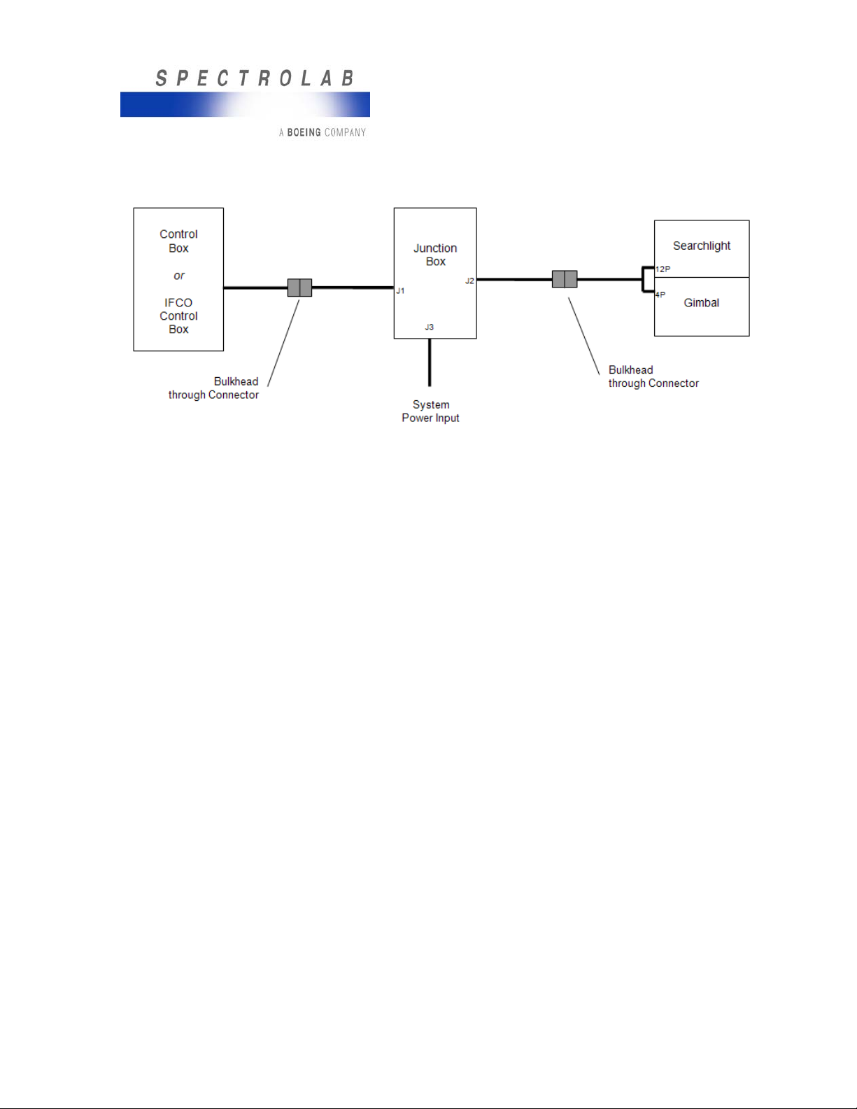
The SX-16 Nightsun®generates voltages in the range of 125 to 150 volts DC and up to 25,000 volts
AC. These voltages are present in both the Searchlight and Junction Box during the start cycle. To
reduce the risk of serious injury from electrical shock:
•Never work alone when working on exposed electrical components.
•During close up inspection activities, remove the Control Box or its cable, or disconnect the
Searchlight cable (power) so that the Searchlight cannot be turned on accidentally.
•High Searchlight voltages normally discharge a few seconds after the start cycle ends. Under
certain malfunction or fault conditions, however, they may remain in the 25,000 VAC range.
oUse a voltmeter to verify that voltage in the Junction Box’s large Capacitor has
discharged from its 125 to 150 VDC level before touching its terminals.
oSimilarly, use a voltmeter to verify that the start signal to the Junction Box terminal
strip is zero. This indicates that all power to the start circuit is off.
2.1.2 Lamp Explosion Hazard
The arc lamp contains xenon gas under pressure. Because the gas inside the lamp is pressurized,
the lamp can explode without warning, especially when it is hot. If it explodes, it may shoot quartz
particles in every direction. Always handle the Searchlight and lamp with caution, and ensure the
safety of others.
•Never operate the Searchlight with the front window or rear cover removed.
•The Searchlight must be cooled to ambient temperature before you work on it.
•If you must handle the arc lamp or work on the Searchlight head with the front lens removed,
wear protective clothing that includes a face shield, a long-sleeve heavy (leather) jacket, and
leather gloves.
•Never leave an exposed xenon lamp unattended.
2.1.3 High Temperature, High-intensity Light
The light from the SX-16 Nightsun®is very powerful; the intense beam can cause serious eye injury
or blindness, and the high temperatures pose a fire hazard. The Searchlight beam is hazardous to
people and certain materials at close range, particularly at distances within 10 feet of the Searchlight.
At a 10 foot distance, the beam intensity can be 100 times as powerful as direct sunlight, and its
reflection can be more intense.
•Do not look into the Searchlight beam, and never shine the light at anyone within 125 feet of
the Searchlight.
•At distances of less than 10 feet, flammable materials (such as human hair, clothing, wiping
rags, paper, cardboard, wood boxes, electrical insulation, and most plastics) can and will be
set on fire.
Source: Spectrolab, Inc. 2
The document reference is online, please check the correspondence between the online documentation and the printed version.

SX-16 Nightsun®Searchlight System
Maintenance Manual
Document 031734-1/Revision A 031734-1 Revision B
January 27, 2014
•During preflight tests on the ground, make sure that the beam is directed away from nearby
people and flammable materials. Make sure to tell people not to look at or to walk through the
Searchlight beam.
•For Searchlight adjustments that require visual observation of the light beam, always wear
dark glasses that are equivalent to welding safety glasses, shade 3.
•To avoid potential impact to eyes from reflected light, never operate the Searchlight in dense
fog or while the aircraft is flying in clouds.
2.1.4 Required Protective Equipment and Clothing
The gas pressure inside the xenon arc lamp makes the lamp a potential explosion hazard. Use the
following safety equipment and wear the following protective clothing when exposed to a bare xenon
arc lamp (for example, when working around the Searchlight head with the front lens removed from
the Searchlight):
•Dark green safety glasses (welding safety glasses, shade 3), such as the Uvex Genesis
(S3207
•Clear safety glasses and face shield, such as the Aerosite/Uvex Highflyer 9177
•Cut-resistant safety gloves (8A38998)
•A long-sleeve, heavy leather jacket.
•A non-flammable target at which to aim the light beam during adjustments (do not use wood,
cardboard, plastic, cloth, or paper as a target); there are two acceptable target types:
oA piece of sheet metal that is 0.032” to 0.125” (0.7 mm to 3 mm) thick and
approximately 3 feet (1 m) across painted with a high temperature resistant black (or
dark brown) paint on one side and white (or light colored) high temperature resistant
paint on the other side. The high temperature resistant paint should be resistant to
500° F (260° C). Barbecue or automotive exhaust manifold paint works well. The
target should be well supported by a stand that is non-flammable. During use, it will
become very hot and should not be handled until it has cooled. A fan can be used to
cool the target.
oA woven aluminum air-handling filter (the washable type used to catch cooking
grease in over the grill venting systems.) If the filter is painted black, it can be an
effective fireproof lamp target. Its large surface area helps to keep it cool. You can
use a fan to help cool the target.
2.1.5 Trained Operators and Maintenance Personnel
Only trained staff with FAA certification should maintain the Searchlight. Furthermore, all installation,
maintenance, troubleshooting, and repairs should be performed only by experienced technicians who
have skill and knowledge about aircraft airframes and electrical systems.
•Because the SX-16 Nightsun®is subject to vibration in its normal operating environment, the
hardware used for system attachment requires positive locking features such as locknuts and
lockwire.
•The SX-16 Nightsun®contains parts that users can maintain and replace; however, there are
no factory approved processes for rebuilding any worn parts; they must be replaced. If you
have questions about what is and what is not repairable, please contact Spectrolab Customer
Service.
2.1.6 Handling Precautions
Do not lift the SX-16 Nightsun®using locations that are not designed to bear the weight or strain of
being lifted.
•During inspection, cleaning, and maintenance, do not grasp the Gimbal motors or the
connector interfaces on the Gimbal or Searchlight to lift it. Instead, use the handle on the
back of the Searchlight, or lift the Gimbal Arm itself (Figure 1).
Source: Spectrolab, Inc. 3
The document reference is online, please check the correspondence between the online documentation and the printed version.

SX-16 Nightsun®Searchlight System
Maintenance Manual
Document 031734-1/Revision A 031734-1 Revision B
January 27, 2014
Figure 1Gimbal
The SX-16 Nightsun®has electrostatic sensitive devices (ESD). Observe precautions for handling
ESD components.
•When maintaining exposed electrical components, never work alone.
•As the Gimbal rotates, the Gimbal motors develop forces that can injure personnel. Keep a
safe distance from the Gimbal to avoid possible injury.
oDo not place fingers inside the Gimbal’s area of motion when the power is on. The
moving parts can trap loose clothing and cause personal injury.
oTo avoid injuries, keep people and loose fitting clothing away from the equipment
during operation.
2.1.7 Installation Location Safety
Before installing the Searchlight, test the installation location:
•During operation, the Searchlight’s high-intensity light beam can cause heat damage to
exposed surfaces, especially if the light is aimed at a surface for long periods of time.
oProvide for heat dissipation from the Searchlight head during operation.
oDo not install the Searchlight in locations that allow the light beam to be aimed at
nearby temperature sensitive surfaces without taking appropriate steps to mitigate
possible damage. The light absorbed by dark colored surfaces may cause them to
reach combustion temperatures under some conditions.
oIf the Searchlight is installed on an aircraft that is equipped with floats, the
mechanical stops for Azimuth and elevation may have to be adjusted. Adjust the
stops to limit the movement of the Searchlight to prevent it from shining directly at the
floats. The Searchlight beam may deteriorate the material in floats at close range.
•Do not expose fuel or other volatile substances to the Searchlight beam.
•Prevent the Searchlight from being aimed in ways that adversely affect the aircraft crew.
•Install a circuit breaker (for the SX-16 Nightsun®) that is accessible to the aircraft crew.
•Make sure that the Searchlight does not interfere with aircraft instrumentation or radios.
•Make sure that the Searchlight does not overload the aircraft’s electrical system when all
other anticipated electrical systems are operating.
Source: Spectrolab, Inc. 4
The document reference is online, please check the correspondence between the online documentation and the printed version.

SX-16 Nightsun®Searchlight System
Maintenance Manual
Document 031734-1/Revision A 031734-1 Revision B
January 27, 2014
2.2 Safety Messages Used in this Manual
This manual contains important safety messages that are identifiable by their appearance. These
safety messages identify hazards and contain information to help you avoid personal injury, and
property damage to the Searchlight, aircraft, or other property. All of these safety messages contain
an exclamation symbol (!) surrounded by a triangle. There are three types of safety message used in
this manual.
•Danger notices indicate a hazardous situation that will result in serious injury if not avoided. A
danger message has the following appearance:
Warning notices indicate a hazardous situation that could result in serious injury if not avoided. A
warning message has the following appearance:
Caution notices indicate a hazardous situation that could result in minor or moderate injury if not
avoided. A caution message has the following appearance:
2.3 Notice Messages
Notice messages are also used in this manual (Figure 2-4). These notices contain special
instructions that are important, but they are not related to safety issues. Notice messages have the
following appearance:
NOTICE
This portion of the notice will contain the special information.
3.0 SETUP
This section describes a typical SX-16 Nightsun®installation. It addresses placement of the SX-16
Nightsun®, safety issues, basic connections for the components, and adjustment of the Gimbal’s
Azimuth stop.
3.1 Searchlight Kits
Searchlight kits are available from Spectrolab to accommodate many commercial and military
helicopters. Each kit contains the hardware (mounting brackets not included) and cables. The kits are
designed for installation by qualified airframe mechanics.
Source: Spectrolab, Inc. 5
The document reference is online, please check the correspondence between the online documentation and the printed version.

SX-16 Nightsun®Searchlight System
Maintenance Manual
Document 031734-1/Revision A 031734-1 Revision B
January 27, 2014
3.2 Guidelines for the Installer
3.2.1 General Guidelines
Spectrolab does not install the SX-16 Nightsun®. It is the responsibility of system installers to ensure
the integrity and safety of the installation, configuration, and integration with the aircraft/structure.
•This manual should not be your sole guide for specific installations. Assess the safety of your
installations on a case by case basis.
•The SX-16 Nightsun®does not require major modifications because it relies on bulkhead
through connectors for system cabling. Consequently, the SX-16 Nightsun®can be installed
on a variety of aircraft/structures. Consult with Spectrolab for assistance in determining your
precise installation requirements.
3.2.2 Technical and Safety Considerations
When selecting a mounting location, the following technical and safety considerations are important:
•Consider aircraft/structure stress, fatigue, and handling characteristics before you approve an
installation design.
•Locate the equipment for favorable equipment operation, and provide optimum mobility for
aiming and focusing.
•On aircraft installations, consider the following elements: balance and weight distribution with
reference to the aircraft center of gravity; aircraft operation; and optimum mobility for aiming
and focusing in all flight patterns.
•Locate the equipment to facilitate adjustments, maintenance, and repairs.
•Route the system cables in ways that minimize their length.
•A stainless steel safety cable secures the Gimbal to the mounting bracket, and another
secures the Searchlight to the Gimbal. If the Gimbal is separated from its mount (or if the
Searchlight is separated from its Gimbal mounting), the safety cables will prevent the Gimbal
or Searchlight from potentially falling free of the aircraft.
Before installing the Searchlight, test the installation location:
•During operation, the Searchlight’s high-intensity light beam can cause heat damage to
exposed surfaces, especially if the light is aimed at a surface for long periods of time.
oProvide for heat dissipation from the Searchlight head during operation.
oDo not install the Searchlight in locations that allow the light beam to be aimed at
nearby temperature sensitive surfaces without taking appropriate steps to mitigate
possible damage. The light absorbed by dark colored surfaces may cause them to
reach combustion temperatures under some conditions.
oIf the Searchlight is installed on an aircraft that is equipped with floats, the
mechanical stops for Azimuth and elevation may have to be adjusted. Adjust the
stops to limit the movement of the Searchlight to prevent it from shining directly at the
floats. The Searchlight beam may deteriorate the material in floats at close range.
oDo not expose fuel or other volatile substances to the Searchlight beam.
oPrevent the Searchlight from being aimed in ways that adversely affect the aircraft
crew.
oInstall a circuit breaker (for the SX-16 Nightsun®) that is accessible to the aircraft
crew.
oMake sure that the Searchlight does not interfere with aircraft instrumentation or
radios.
oMake sure that the Searchlight does not overload the aircraft’s electrical system
when all other anticipated electrical systems are operating.
3.3 Overview of System Connections
The SX-16 Nightsun®includes a Control Box, Junction Box, Gimbal, Searchlight, and cables. Figure 2
depicts the connections between the main components of the SX-16 Nightsun®. It identifies the
Source: Spectrolab, Inc. 6
The document reference is online, please check the correspondence between the online documentation and the printed version.

SX-16 Nightsun®Searchlight System
Maintenance Manual
Document 031734-1/Revision A 031734-1 Revision B
January 27, 2014
components, the connectors on each component (J1 on the Junction Box for example), and the
cables attached to each connector.
Figure 2Overview of SX-16 Nightsun®Connections
3.4 Overview of Cabling
The SX-16 Nightsun®relies on various cables for power and communication. These cables use
bulkhead through connectors to support installation on a variety of vehicles.
•Control Box connector to Bulkhead control connector
•Bulkhead control connector to Junction Box connector
•Junction Box connector to Bulkhead system power input connector
•Junction Box Gimbal/Searchlight connector to Bulkhead connector
•Bulkhead connector to Gimbal and Searchlight connectors
3.5 Connections to the Junction Box
The Junction Box links most of the SX-16 Nightsun®components. This section of the manual
addresses the following connections:
•Junction Box to the Control Box
•Junction Box to the Gimbal assembly and Searchlight
•Junction Box to the input power
3.5.1 Junction Box to Control Box
•In the compartment where the Control Box will be used to operate the Searchlight, connect
one end of the control cable to the connector on the base of the Control Box. Connect the
other end of the cable to the bulkhead through connector.
•On the other side of the bulkhead, connect one end of the straight control cable to the
bulkhead through connector. Connect the other end of the cable to the J1 connector on the
Junction Box.
3.5.2 Junction Box to Gimbal Assembly and Searchlight
•In the compartment where the Junction Box is installed, connect one end of the Junction Box
to bulkhead cable to the J2 connector on the Junction Box. The other end of the cable
connects to the bulkhead through connector leading to the exterior of the vehicle, where the
Gimbal assembly is installed.
•On the exterior of the aircraft:
Source: Spectrolab, Inc. 7
The document reference is online, please check the correspondence between the online documentation and the printed version.

SX-16 Nightsun®Searchlight System
Maintenance Manual
Document 031734-1/Revision A 031734-1 Revision B
January 27, 2014
oConnect one end of the bulkhead to Gimbal cable to the bulkhead through connector.
On the other end, connect the Gimbal portion of the cable to the 4 pin connector on
the Gimbal.
oConnect the Searchlight portion of the cable to the 12-pin connector on the
Searchlight.
3.5.3 Junction Box to Input Power
Make sure that the Control Box On switch is set to the Off position.
Connect one end of the power cable to the J3 connector on the Junction Box. Connect the other end
of the power cable to the power source.
4.0 GIMBAL ASSEMBLY
4.1 Functional Description
The Gimbal assembly (Figure 3) has a U-shaped yoke (called a Gimbal arm) made of ¼” x 3” high
strength aluminum or steel. When fully assembled, it serves the following functions:
oMechanically supports the Searchlight and the attachment to the aircraft.
oProvides the electrical and communication link between the Searchlight and Junction
Box.
oContains gears, electronic equipment, and separate DC motors that adjust the
Searchlight’s Azimuth and Elevation positions. Consequently, the Gimbal assembly
enables the Searchlight to be pointed in various directions.
4.2 Gimbal Configurations Available
4.2.1 Standard Gimbal Assembly (Current) Description
The current configuration, which was introduced in August 2004 (Figure 3), has two moveable stop
blocks attached to the Azimuth ring by two shoulder bolts. It also has a high-strength, stationary
shoulder bolt mounted on the doubler plate. In Figure 3, the main Gimbal components are illustrated.
Figure 3 Gimbal Assembly (Current Standard Configuration)
Source: Spectrolab, Inc. 8
The document reference is online, please check the correspondence between the online documentation and the printed version.

SX-16 Nightsun®Searchlight System
Maintenance Manual
Document 031734-1/Revision A 031734-1 Revision B
January 27, 2014
4.2.2 Enhanced Gimbal Assembly Description
The Enhanced (Unibody) Gimbal (Figure 4) is constructed with high-strength Aluminum Alloy and
does provide an unrestricted service life limit as with the other configurations. The Enhanced Gimbal
integrates reinforcement features such as a one-piece arm, ribbed bends and a flared design to
provide structural integrity. Precision Gearboxes augment performance by allowing backlash of less
than 1°, adding a sealed enclosure, dry lube treated gears, and a precise fit end cap. The Enhanced
Gimbal high-speed motors offer a slew rate of up to 18° per second. Adjustable Elevation stop blocks
are incorporated to improve ease of moving of upper and lower elevation limits in 2° increments.
Elevation stop block shown is for illustration purposes and may vary from current design. The
enhanced Gimbal is intended to be backwards compatible to all SX-16 Nightsun® Searchlight
systems.
Figure 4Gimbal Assembly (Enhanced)
4.2.3 Adjustable Elevation Stop Blocks (Enhanced Gimbal Only)
Each side of the Elevation Stop Blocks marked for the configuration of system; WHT LT on one side
and IFCO on the opposite side. The stop blocks may be adjusted for the required elevation travel
range. In addition to being moved, the stop blocks can be trimmed on the slotted end of the stop
block for more precise travel limit requirements.
Source: Spectrolab, Inc. 9
The document reference is online, please check the correspondence between the online documentation and the printed version.

SX-16 Nightsun®Searchlight System
Maintenance Manual
Document 031734-1/Revision A 031734-1 Revision B
January 27, 2014
Figure 5Example of Enhanced Gimbal with Elevation Stop Blocks Installed for White Light
(WHT LT) Configuration
4.3 Standard (Older, Pre-August 2004)
The older standard configuration (Figure 6) has adjustable Azimuth horizontal Roll Pins that are
pressed into radiating holes on the bottom of the Gearbox. It also has a fixed vertical Roll Pin
mounted on top of the doubler plate. In Figure 6, the main Gimbal components are illustrated.
Figure 6Gimbal Assembly (Older Standard Configuration)
4.3.1 Additional Gimbal Variations
Spectrolab Gimbal assemblies also include configurations that accommodate:
•Various mounting locations
•Various speed and weight restrictions: Reference Safety and Service Bulletin #SL 0899-01
Source: Spectrolab, Inc. 10
The document reference is online, please check the correspondence between the online documentation and the printed version.

SX-16 Nightsun®Searchlight System
Maintenance Manual
Document 031734-1/Revision A 031734-1 Revision B
January 27, 2014
oA light-weight Aluminum version for slow speed aircraft (up to 168 knots) has a
maximum service life of 7 years.
•A heavier, high-strength Steel version for high-speed aircraft (up to 271 knots) and
has a maximum service life of 10 years
•Our SpectroLink system enables accessory equipment (such as a movable camera) to
control the movements of the Searchlight. As a result, the movements of the accessory
equipment can be synchronized with the movements of the Searchlight. SpectroLink,
provides a stow feature, and it can be attached to the Gimbal assembly and Junction Box.
Reference the SpectroLink Operations Manual P/N 033600 for additional information.
•Some users modify the Searchlights by adding limit switch type sensors or optical switches
that are tied into a stow circuit. In general, these circuits enable the Searchlight to rest in a
home position that is horizontal (and points forward) when it is turned off. This increases the
Searchlight to ground clearance on some belly mounted installations.
4.3.2 Gimbal Part Numbers Available by Description
The following are some of the available Gimbals.
019059 Series (Aluminum)
-10 Standard
-110 Standard High-Speed
-130 SpectroLink
-140 IFCO SpectroLink
-210 Enhanced (Uni-body)
-230 Enhanced (Uni-body) with SpectroLink
022955 Series (Steel)
-21 Standard
-121 Standard High-Speed
-130 SpectroLink
-140 IFCO SpectroLink
4.3.3 Elevation Attachment and Movement
In addition to the safety cables, two removable Wing Bolts (one on each side of the Searchlight)
attach the Searchlight to the Gimbal assembly. The Wing Bolts act as extensions of the bosses that
are welded to each side of the Searchlight housing.
•The elevation Gearbox and motor are mounted on one side of the Gimbal arm, which is
called the drive side. On the drive side of the Gimbal arm:
oThe Wing Bolt passes through the elevation Gearbox (through the Elevation drive’s
hollow shaft) into the Searchlight’s other mounting boss.
oA square drive output shaft on the Elevation Gearbox slips into a mating socket in the
Searchlight’s elevation stop, and this transmits the output power from the Gearbox
directly to the Searchlight.
oScrew heads (or drive pins) project from the inside of the Gimbal arm and come into
contact with the Searchlight’s Elevation Stop.
oThe Elevation Stop limits Searchlight movement and prevents it from pointing in
unwanted directions. The Elevation Stop is fixed (cannot be adjusted).
oThe service loop between the elevation Gearbox motor and Gimbal connector
permits motion between the Gimbal Arm and the Azimuth Gearbox, which remains
stationary.
Source: Spectrolab, Inc. 11
The document reference is online, please check the correspondence between the online documentation and the printed version.

SX-16 Nightsun®Searchlight System
Maintenance Manual
Document 031734-1/Revision A 031734-1 Revision B
January 27, 2014
•On the non-drive side of the Gimbal Arm, the threaded portion of the Wing Bolt projecting
outward from the spacer and arm bearing can be viewed. This portion of the Wing Bolt
screws into one of the Searchlight’s mounting bosses and extends through the Arm Bearing.
4.3.4 Azimuth Attachment and Movement
The Azimuth Gearbox and Motor are mounted at the top of the Gimbal arm (where it attaches to the
aircraft).
•The Azimuth Gearbox has a shaft that secures the Searchlight to the aircraft mounting
bracket through four mounting bolts. This shaft supports the entire weight and aerodynamic
load of the Searchlight and Gimbal assembly.
•A combination of fixed (cannot be adjusted) and Azimuth stops limit Searchlight motion to
prevent it from pointing in unwanted directions. These stops are located around the bottom of
the Azimuth Gearbox and on the top of the Gimbal Arm doubler plate.
4.4 Wing Bolts
The Wing Bolts on each side of the Gimbal yoke are stainless steel 5/16”-24 bolts, and they have
wing handles welded to the bolt heads.
•A 1/16” diameter stainless steel wire rope (or lanyard) with a safety pin type clip on the free
end is permanently attached to each Wing Bolt. The clip is attached to a bracket on the side
of the Gimbal.
•The lanyard helps to prevent the Wing Bolt from accidentally unfastening. It keeps the Wing
Bolt from being separated from the Gimbal when the Searchlight is removed. These also act
as safety cables for both Wing Bolts and ensure that the Wing Bolts cannot be separated
from the Gimbal or aircraft during flight.
4.4.1 Inspection
The Wing Bolts should be inspected during preflight (or daily) inspection. They also should be
inspected every 6 months or 300 flight hours or 100 operation hours. Use the following inspection
procedures:
•Daily:
oVerify that both Wing Bolts are in place and that the lanyards are connected to the angle clips
on the Gimbal.
oVerify that both Wing Bolts are fully hand tight. If not, tighten them.
oVerify that the hairpin clip on the lanyard is properly closed and secure.
oVerify that the lanyards do not have more than 10% of the wire strands broken. If they are
broken or if many sharp individual wires are sticking out, replace the Wing Bolt and lanyard.
•Every 6 months or 300 flight hours or 100 operation hours, loosen the lanyard and try to unscrew
both Wing Bolts, one at a time.
•The locking feature (which is part of the threaded insert into which the Wing Bolt is screwed)
should resist the attempt to unscrew the Wing Bolts. Resistance, however, should be moderate;
you should be able to unscrew the Wing Bolt without a wrench. If there is moderate resistance,
the Wing Bolt is fine. When you re-insert the bolt, lubricate the bolt lightly to minimize future
galling and insert wear.
•If there is heavy resistance, the Wing Bolt threads are probably damaged or partially galled; the
Wing Bolt must be replaced. If there is no resistance, the Searchlight threaded insert is probably
worn out and must be replaced. The replacement procedures for the insert and the bolt are in
Test of Wing Bolt Housing Boss Inserts section of this manual.
4.5 Gimbal Wiring
4.5.1 Inspection Schedule
The Gimbal wiring is exposed to the outdoor environment, to flight aerodynamics such as wind and
rotor downwash, and the flexing and abrasion associated with the Azimuth (left-right) motion of the
Gimbal (while the Gearbox housing and connector mount remains stationary). Consequently, the
wiring should be inspected daily (preflight) and every 3 months or 100 flight hours or 50 operating
hours.
Source: Spectrolab, Inc. 12
The document reference is online, please check the correspondence between the online documentation and the printed version.

SX-16 Nightsun®Searchlight System
Maintenance Manual
Document 031734-1/Revision A 031734-1 Revision B
January 27, 2014
4.5.2 Inspection Procedure
4.5.2.1 Standard Connector
The Spectrolab Gimbal has a circular 4-pin quick-release standard connector that supplies power to
the Gimbal motors (the Searchlight has its own connector). The connector is mounted on an
aluminum bracket that screws into the Azimuth Gearbox housing with four mounting screws (Figure
7).
•The bracket can be installed so that it points to the right, left, or down.
•The gold plated pins on the connector connect to a mating connector on the external
Searchlight/Gimbal cable.
•Inspect the connector to verify its condition:
oThe pins should be shiny and free of corrosion or tarnish, and the body of the
connector should not be severely corroded or broken.
oThe small radial pins on the outside of the connector shell must be intact for the
connector to be seated properly.
oThe four mounting screws that hold the connector to the mounting bracket should be
in place and tight. If they are not tight, remove the screws, apply a drop of Loctite®on
the loose screws, replace them, and tighten them.
Figure 7Gimbal Electrical Connector
4.5.2.2 Alternate Connectors
A few Gimbals that are used on fixed wing aircraft and on some boats will have an alternate
connector. Further, if you have added aftermarket sensors or switches to the Gimbal, these sensors
or switches will have a second, separate connector. If not, you may have to replace the standard 4-
pin connector with one that has more pins.
4.5.2.3 Motor Wires
The condition of all motor wires is important. These wires must be able to flex, permitting the motion
that takes place with respect to the Azimuth Gearbox and Gimbal arm. Inspect the motor wires for
chafing, pinched wires, the condition of the insulation, evidence of stress, and general serviceability. If
the wires are not in good condition, refer to the Replacement of Wiring and Electrical Connector for
replacement procedures.
4.5.3 Service Loops
The Gimbal arm rotates with respect to the fixed Azimuth Gearbox. Consequently, the wire that runs
between the elevation motor and the electrical connector on the Azimuth Gearbox requires a service
loop to permit the motion of the Gimbal arm (Figure 3).
The service loop should be long enough to enable the Gimbal to move to its mechanical limits in both
directions without pulling on the motor wire. If the motor wire pulls repeatedly, it will eventually break
off from the terminals on the elevation motor (inside the boot).
Inspect the service loop as you manually push the Gimbal from one limit to the other. The wire must
not pull on the motor connection or on the area where it enters the connector bracket. If the wire pulls,
readjust the cable ties (also called lead dressing or lead dress) to increase the amount of free wire
until the wire no longer pulls.
Source: Spectrolab, Inc. 13
The document reference is online, please check the correspondence between the online documentation and the printed version.

SX-16 Nightsun®Searchlight System
Maintenance Manual
Document 031734-1/Revision A 031734-1 Revision B
January 27, 2014
4.5.4 Cable Ties
The motor wires are cut at the factory so that they are long enough to allow a full range of Gimbal
motion. The length of the wire usually exceeds the amount needed to permit a full range of motion.
Consequently, the excess wire is tied down with cable ties (also called lead dressing or lead dress).
Inspect the condition of the cable ties, and adjust them so that the service loop is long enough but not
too long.
If you must replace the cable ties, use black replacement ties that are specifically rated for outdoor
use. The white and clear ties are not resistant to outdoor levels of sunlight, and they will deteriorate
rapidly.
4.6 Mechanical Stops
Mechanical stops limit the motion of the Gimbal in both Azimuth and Elevation. These mechanical
stops prevent the Searchlight from being pointed in unwanted directions. When the Gimbal or
Searchlight hits these mechanical stops while the motor is still running, the clutches in the Gearboxes
begin to slip. This stops the motion of the Gimbal or Searchlight.
The Azimuth and Elevation mechanical stops should be inspected as part of a pre-flight inspection
and every 6 months or 300 flight hours or 100 operation hours.
In addition, to the mechanical stops (supplied by Spectrolab), some Searchlight systems include
electronically programmable stops as part of ancillary equipment (such as a moving camera) that has
been specially installed. Adjustment of these programmable stops is addressed in the documentation
that accompanies the ancillary equipment.
4.6.1 Elevation Motion Stops
Elevation motion is limited by the Searchlight Elevation stop (Figure 9) attached to the Searchlight
housing, and the stops on the inside edge of the Gimbal. When the Elevation stop on the Searchlight
housing comes into contact with the stop on the Gimbal that project outward from the inside of the
Gimbal arm such as hardware, stop pins, or adjustable stop blocks.The travel limits vary according
to the configuration. The limits are outlined on the coordinating envelope drawing listed on the
Applicable Documents section of this manual
The Test of Elevation Stop and Adapter Plate Threaded Holes and Elevation Stop Internal Square
Drive and Stop Hardware section addresses the elevation stop and its inspection procedures. If the
Elevation Gearbox is removed from the Gimbal arm, verify the attaching screws are installed in the
same locations that they were removed. This is necessary for the Elevation stop to work properly.
Excessive wear to the central square drive hole also causes backlash. If the central square hole is
worn, it must be replaced.
Figure 8Gimbal Elevation Stops (From Left to Right: Standard, IFCO, Enhanced)
Source: Spectrolab, Inc. 14
The document reference is online, please check the correspondence between the online documentation and the printed version.

SX-16 Nightsun®Searchlight System
Maintenance Manual
Document 031734-1/Revision A 031734-1 Revision B
January 27, 2014
Standard Elevation Stop (018569-1)
IFCO Elevation Stop (030535 Rev D and previous)
IFCO Elevation Stop (030535 Rev E and later)
Figure 9Various Elevation Stops
4.6.1.1 Replace an Searchlight Elevation Stop
Required Tools and Supplies (Not provided by Spectrolab):
Description
Torque Wrench with capacity of 24 inch-pounds
Torq Set Insert Bit (TSI-8)
Loctite Thread Locker 222
•With the Searchlight removed from the Gimbal, make note of the orientation of the elevation stop
since the replacement will be installed in the same orientation. Remove the four (4) torque set
flat head screws (P/N NAS1102E08-5P, 8-32 x 5/16 LG) attaching the existing Elevation stop to
the Searchlight assembly with the torque set insert bit (attached to driver).
Figure 10 Elevation Stop Removal
•Install the replacement Elevation stop in the same orientation the previous elevation stop was
installed.
•With Loctite applied to screw threads, firmly tighten the 4 screws (20-24 inch-lbs).
4.6.1.2 Replace the Elevation Roll Pin (IFCO Gimbal Only)
This Procedure Applies the following Gimbal Assemblies:
Source: Spectrolab, Inc. 15
The document reference is online, please check the correspondence between the online documentation and the printed version.

SX-16 Nightsun®Searchlight System
Maintenance Manual
Document 031734-1/Revision A 031734-1 Revision B
January 27, 2014
022955-22
019059-111
022955-51
Required Tools and Supplies:
Locking Pliers
Wrench
Hex Hex Wrench
Loctite 272
•Remove the Searchlight from the Gimbal Assembly.
•With Locking Pliers, compress the Roll Pin then remove by twisting and pulling away from the
Gimbal Arm at the same time (Figure 11).
Figure 11 Remove the Roll Pin
•Install replacement Roll Pin by reversing previous steps.
•Re-install the Searchlight Head and test for interference.
4.7 Azimuth Motion Stops
4.7.1 Current Configuration (Since August 2004)
The current Azimuth stop configuration was introduced in August 2004. It consists of two adjustable
stop blocks. Each stop block is attached to the Azimuth Adapter ring by two shoulder bolts (Figure
12). The stop blocks limit movement of the Gimbal when the stop blocks come into contact with a
high- strength stationary shoulder bolt that is mounted on the Gimbal Arm through the doubler. You
can detach and reposition the stop blocks to restrict Azimuth movement according to your installation
and aircraft requirements.
Figure 12 Current Azimuth Stop Configuration
Inspect the Azimuth stops by checking the torque of the following:
•All four stop block shoulder bolts that are attached to the Azimuth Ring
oEach 8-32 stop block shoulder bolt should be torque to 20 ±2 inch-pounds.
Source: Spectrolab, Inc. 16
The document reference is online, please check the correspondence between the online documentation and the printed version.

SX-16 Nightsun®Searchlight System
Maintenance Manual
Document 031734-1/Revision A 031734-1 Revision B
January 27, 2014
•Stationary precision shoulder bolt that is mounted on the Gimbal arm.
oEach ¼”-20 precision shoulder bolt should be torque to 78 ±2 inch-pounds.
•In addition, regularly inspect the condition of the stop block shoulder bolts and the stationary
precision shoulder bolt. Replace them if necessary.
Azimuth motion also is limited by the length of the motor wiring. If it is long enough, the motor (and
Searchlight) wiring enables the Searchlight to rotate a maximum of 170° to the left and 170° to the
right of a center position with respect to the Gimbal (this assumes that the Searchlight/Gimbal are
pointed directly forward with relation to the aircraft). The maximum potential movement of the
Searchlight, however, will be compromised if the wire becomes twisted around or hampered by the
Gimbal components.
4.7.2 Old Configuration (Before August 2004)
The old Azimuth stop configuration applies to all Gimbals that were in service before August 2004.
Azimuth motion is limited by the length of the motor wiring and the position of three Roll Pins (called
mechanical stops) as shown in Figure 13.
If it is long enough, the motor (and Searchlight) wiring enables the Searchlight to rotate a maximum of
170° to the left and 170° to the right of a center position with respect to the Gimbal (this assumes that
the Searchlight/Gimbal are pointed directly forward with relation to the aircraft). The maximum
potential movement of the Searchlight, however, will be compromised if the wire becomes twisted
around or hampered by the Gimbal components.
Azimuth motion is limited by the position of three Roll Pins that are 3/16” in diameter.
One of the Roll Pins (called the vertical Roll Pin) is pressed into the top outside edge of the Gimbal
arm’s doubler plate. When fully inserted, it projects 0.375” above the surface of the Gimbal arm and
moves with the Gimbal arm’s rotation. The position of this pin is fixed. It moves back and forth
between the two adjustable horizontal Roll Pins. When it comes into contact with either one of the
horizontal Roll Pins, the motion of the Searchlight stops.
Two of the Roll Pins (called the horizontal Roll Pins) are pressed into radiating holes on the outer
edge of the Gearbox adapter, which is mounted on the underside of the Azimuth Gearbox. These two
Roll Pins can be moved to a number of different positions in the radiating holes of the adapter to halt
the motion of the Searchlight at various points. When the Roll Pin on the Gimbal comes into contact
with one of the Roll Pins pressed into the adapter (in either direction), the motion of the Searchlight
stops.
All Roll Pins are subject to fatigue and eventual breakage. Inspect them on a regular basis and
replace them if necessary.
Figure 13 Azimuth Stop Roll Pins (Older Configuration)
4.7.3 Vertical Roll Pin Inspection
To inspect the vertical Roll Pin (located on the top outside edge of the Gimbal arm’s doubler plate):
Source: Spectrolab, Inc. 17
The document reference is online, please check the correspondence between the online documentation and the printed version.

SX-16 Nightsun®Searchlight System
Maintenance Manual
Document 031734-1/Revision A 031734-1 Revision B
January 27, 2014
•First try to wiggle the Roll Pin with needle nose pliers. It should have a tight fit in its hole and
should be very stiff.
•Push the Gimbal to the left and to the right as far as it will go until the vertical Roll Pin makes firm
contact against the horizontal Roll Pins (mounted on the adapter on the Azimuth Gearbox) in both
directions. If the vertical Roll Pin bends, this means that it is either cracked or loose in its hole. If it
is cracked or loose, replace it immediately.
To replace the vertical Roll Pin, the Gimbal arm will need to be removed from the Azimuth Gearbox.
Prior to the arm removal:
•Use a permanent marker to mark the relative positions of the shaft, the Gimbal arm, and the
Gearbox housing. It can be difficult and time consuming to determine the correct relative
positions.
•Although the arm will fit on the shaft in any position, the relative location of the Gearbox mounting
bolts, motor position, and Azimuth stops may change if the arm is not replaced in the same
relative location with respect to the Gearbox housing.
•To avoid having to recreate the original setup, identify the relative location of the parts as they
come off so that you can reassemble them in exactly the same orientation.
•To separate the arm from the shaft, remove the attaching nut. If the arm does not slide off easily,
use a gear puller to remove the arm from the splined shaft. As you remove the shaft, notice and
mark the orientation of the spacer bushing between the Gearbox and the arm
Once the Gimbal arm is removed:
•Compress the pin with vise-grip pliers, and pull it out. If the pin breaks, use a screw extractor to
remove the pin.
•Insert a new pin into the hole. Hold it in position with long nose pliers while tapping it into place
with a small steel hammer.
oIf the pin does not fit snuggly in the hole, the hole is distorted or worn out (enlarged). If
the hole has been enlarged in this way, replace the Gimbal arm. There is no repair
procedure for an enlarged Roll Pin hole.
oIf the new pin fits snug, reassemble the spacer and arm on the shaft. Tighten the Azimuth
shaft nut to 50-60 foot-lbs. Hold the Gimbal arm in a soft jaw vise to tighten the nut.
Attach safety wire between the nut and the adjacent drilled head screw.
•Replace the Gimbal arm on the aircraft, and make sure that the service loops and cable ties are
correctly adjusted as described in the Service Loops section of this manual.
•Reattach all safety cables on the Gimbal assembly, Searchlight, and aircraft.
•Replace the Searchlight and make a full system functional check.
4.7.4 Horizontal Roll Pin Inspection
The two horizontal Roll Pins are pressed into radiating holes on the outer edge of an adapter that is
mounted on the underside of the Azimuth Gearbox. These pins must be in place and tight for safe,
predictable operation of the Searchlight. To inspect the horizontal Roll Pins:
•First try to wiggle the Roll Pins with needle nose pliers. They should have a tight fit in the holes
and be very stiff.
•Push the Gimbal to the left and to the right as far as it will go until the vertical Roll Pin makes firm
contact against the horizontal Roll Pins in both directions. If the vertical Roll Pins bend, this
means that they are either cracked or loose in their holes. If either one is cracked or loose,
replace it immediately.
•To replace a horizontal Roll Pin:
•Compress the pin with vise-grip type pliers, and pull it out. If the pin breaks, use a screw extractor
to remove the pin. Since the Roll Pins are made of spring steel, this will be very difficult. An extra-
hard drill bit may be needed to remove the pin.
•Insert a new pin into the hole. Hold it in position with long nose pliers while tapping it into place
with a small steel hammer. If the pin does not fit snug in the hole, the hole is distorted or worn out
(enlarged). If the hole has been enlarged in this way, there are two options:
Source: Spectrolab, Inc. 18
The document reference is online, please check the correspondence between the online documentation and the printed version.

SX-16 Nightsun®Searchlight System
Maintenance Manual
Document 031734-1/Revision A 031734-1 Revision B
January 27, 2014
oA fresh hole can be used on the same adapter ring by rotating it 90, 180, or 270° such
that a fresh hole is in the desired location.
oThe ideal solution, however, is to replace the adapter ring.
oIn either case, you the adapter ring will need to be removed from the bottom of the
Azimuth Gearbox shaft.
Before removing the arm, use a permanent marker to mark the relative positions of the shaft, the arm,
all Roll Pins, and the Gearbox housing. Make a simple sketch to do this.
•Although the arm will fit on the shaft in any position, the relative positions of the Gearbox
mounting bolts, motor position, and Azimuth stops may change if the arm is not replaced in
the same location relative to the Gearbox housing.
•It can be difficult and time consuming to determine the correct relative positions. To avoid
having to recreate the original setup, identify the relative location of the parts as they come
off so that you can reassemble them exactly in the same orientation.
•To separate the arm from the shaft, remove the attaching nut. If the arm does not slide off
easily, use a gear puller to remove the arm from the shaft. As the shaft is removed, notice
and mark the orientation of the spacer bushing between the Gearbox and the arm.
Once the Gimbal arm is removed:
•Unscrew the adapter from the bottom of the Gearbox. There are two options:
•One option is to rotate the adapter 90, 180, or 270° so that a fresh hole is in the desired
location.
•A second option is to replace the adapter with a new one.
After you have rotated or replaced the adapter:
•Reassemble the spacer and arm on the shaft.
oTighten the Azimuth shaft nut to 50 to 60 foot-pounds. Hold the Gimbal arm in a soft jaw
vise to tighten the nut.
oAttach safety wire between the nut and the adjacent drilled head screw.
oInstall new Roll Pins in the adapter in the same locations as the old ones.
•Replace the Gimbal arm on the aircraft, and make sure that the service loops and cable ties
are correctly adjusted. Reference the Service Loops section of this manual
•Reattach all safety cables on the Gimbal assembly, Searchlight, and aircraft.
•Replace the Searchlight and make a full system functional check.
4.8 Gimbal Arms
The Gimbal Arms form a U-shaped yoke that is made of machined aluminum or steel. Standard
Gimbal Arms except for the Enhanced version, include the following basic components (Figure 14),
the Enhanced Gimbal Arms are made one piece of Aluminum (Unibody):
•The large, curved arms.
•A doubler plate that increases the strength of the arms at the top of the yoke, where it is
attached to the aircraft.
•Rivets that join the arms of the yoke to the doubler plate.
•A coating of paint or powder-coat finish.
Figure 14 Upper Part of Gimbal with Doubler Plate and Rivets
Source: Spectrolab, Inc. 19
The document reference is online, please check the correspondence between the online documentation and the printed version.

SX-16 Nightsun®Searchlight System
Maintenance Manual
Document 031734-1/Revision A 031734-1 Revision B
January 27, 2014
4.8.1 Standard Gimbal Arm Inspection Need and Schedule
The paint or powder-coat finish protects the surface and interior sections of the Gimbal arms from
corrosive salt spray or other atmospheric corrosives. Of particular concern is the finish in the area of
the rivets. Corrosion in the area of the rivets can lead to weakening, cracks, and failure of the yoke to
support the Searchlight. This can lead to the Searchlight assembly being suspended by the safety
cable. Regardless of environmental conditions:
•The maximum service life of Aluminum Gimbal arms is 7 years.
•The maximum service life of Steel Gimbal arms is 10 years.
•Consequently, it is necessary to inspect the yoke and the area of the doubler plate rivets for
evidence of cracks or corrosion.
•Conduct a daily visual inspection for cracks, chipped or peeling paint, loose or defective
rivets, and corrosion.
•Conduct a detailed inspection every 6 months or 100 Operational Hours or every 300 flight
hours, whichever comes first. The inspection should be conducted by a qualified airframe
mechanic who is trained in the visual inspection of rivets and mechanical structures.
4.8.2 6 Month Inspection (or 300 Flight Hours or 100 Operational Hours)
4.8.2.1 Preparation
To prepare the Gimbal arms for inspection:
•Separate the Searchlight from the Gimbal and remove the Gimbal from the aircraft.
•Clean the Gimbal arms thoroughly using a general purpose aircraft cleaner, a mild solvent
such as isopropyl alcohol, or a soapy water solution. Remove all traces of dirt, grease, debris,
or salt buildup.
•Dry the Gimbal arms thoroughly.
4.8.2.2 Inspection Procedure
In a well-lit area, examine all parts of the Gimbal arms; pay particular attention to the area of the
doubler plate and the rivets.
•Inspect for signs of cracks, corrosion, or chipped or peeling paint.
oIf any cracks or any loose or broken rivets are found, replace the arm.
oIf isolated areas of corrosion may be found underneath the paint or powder-coating.
This can occur at the site of a pin hole in the coating, and it may appear as a lump in
the paint or powder-coating. If a lump is found in the paint or coating, remove the
paint locally with a sharp blade to determine if there is corrosion underneath.
oIf evidence of corrosion is found, peeling, or chipped paint, note these areas so that
you can inspect them more closely under magnification.
•Use a handheld magnifier of 5x to 10x to examine any corrosion spots that were invisible to
the unaided eye. Under magnification, determine the extent of the corrosion.
oIf the corrosion is only at the surface level, clean off the corrosion and apply touch-up
paint to the area as described in the Arm Repair section of this manual.
oLook for evidence of separation or peeling of the aluminum. Any corrosion or pitting
that is more than 0.01” (0.25 mm) deep or more than 0.125” (3.2 mm) in diameter
should not be repaired. Instead it must be replaced.
•Try to insert a feeler gauge between each of the ends and sides of the doubler plate and the
Gimbal arm.
oUse a feeler gauge that is 0.005” thick and ½” wide (0.125 mm x 10 mm).
oIf more than 0.25” (6 mm) of a feeler gauge can be inserted, it indicates a separation
between the Gimbal arm and the doubler plate. If such a separation is measured,
replace the Gimbal arm.
•The Gimbal arm may return to service under the following conditions; otherwise, you must
replace the Gimbal arms:
oIf corrosion, cracks, loose rivets, doubler plate separation, peeling paint, or chipped
paint were not found.
Source: Spectrolab, Inc. 20
The document reference is online, please check the correspondence between the online documentation and the printed version.
Other manuals for SPECTROLAB SX-16 Nightsun
3
Table of contents
Other Boeing Floodlight manuals
Popular Floodlight manuals by other brands

Cooper Wheelock
Cooper Wheelock XB11 specification

Exterrain
Exterrain HARRIER50R user manual

Hubbell
Hubbell Chalmit ARRAN X ARXI/30/LE Installation, operation and maintenance instructions

Extreme Tent
Extreme Tent EXLED-001 Safety instructions and operation manual

GE
GE Evolve EFH1 installation guide

EXC
EXC EXC-B200CBH manual