BOGBALLE S Series User manual

0407-17-08-18 V8
S-line
Operator’s Manual
S-line
GB

S-line
1
CONTENTS
SUBJECT
Page
MAIN SETTINGS
…………………………………..…
2
OVERVIEW
……………………………………..
3
PRACTICAL USE................................................
……………………………………..
4
CHECK OF SPREADER –before use
……………………………………..
7
TECHNICAL SPECIFICATIONS, general
……………………………………..
8
TECHNICAL SPECIFICATIONS, specific
……………………………………..
8
STANDARD EQUIPMENT
……………………………………..
8
OPTIONAL EQUIPMENT
……………………………………..
9
MAINTENANCE AND CARE
Normal maintenance………………….........9
Protection, friction clutch .…………..........10
Lubrication………………………………….11
Generally…………………………………. ..11
Spreading vanes…………………………. 11
……………………………………..
9
GUARANTEE / RESPONSIBILITY
……………………………………..
12
GENERALLY
……………………………………..
12
SAFETY and PROTECTION against ACCIDENTS
……………………………………..
12
USING THE CALIBRATION KIT
……………………………………..
13
S2 TRAIL
Overview………………….. .......................15
Practical use .………….............................16
Agitator…………………………………. .....16
Wheel slip…………………………………. 17
Technical data general/specific................18
Optional equipment…………....................18
……………………………………..
15
EC DECLARATION OF CONFORMITY
…………………………………..…
19
PICTOGRAMS
……………………………………..
20
SYMBOL EXPLANATION
……………………………………..
21
NOTES
……………………………………..
22
NB. Fitting instructions for different optional equipment
–are supplied with the optional equipment!
SPECIAL ATTENTION PLEASE!
In order to avoid that the material ’compress’ with the risk of
blocking the agitator and outlet follow these rules:
Always fill in the material cautiously –in a steady flow!
Never put pressure on the material during/after filling!
Avoid to ”compact” the material when driving for a longer period of time!
When the shutter/outlet is closed the spreading disc / agitator should not rotate!
NEVER leave the spreader with material in the hopper!

S-line
2
MAIN SETTINGS
PTO- speed 400 RPM.
TILT-angle Mounted Horizontal
WORKING HEIGHT from ground to disc 60 CM
QUANTITY SETTING See chart G/M2
VANE POSITION See chart
LIMITER f/ SPREAD WIDTH See chart
Spread Chart
Example
Spread Width : 2 Meter
Speed : 15 Km/H
Quantity : 31 G/M2
Scale : 2,50
Vane Setting : All 4 vanes are set in position 2
Limiter : Minimum
PTO: rpm 18-09-2007
2S3
5 10 15 20
0000 0,0 - - -
7322 1,1 3 - 3 - 3 - 3
36 18 12 9 6,0 3 - 3 - 3 - 3
92 46 31 23 15,3 3 - 3 - 3 - 3
145 73 48 36 24,2 3 - 3 - 3 - 3
181 90 60 45 30,2 3 - 3 - 3 - 3
223 111 74 56 37,1 2 - 2 - 2 - 2
277 138 92 69 46,1 2 - 2 - 2 - 2
351 176 117 88 58,5 2 - 2 - 2 - 2
416 208 139 104 69,3 2 - 2 - 2 - 2
452 226 151 113 75,3 2 - 2 - 2 - 2
470 235 157 118 78,4 1 - 2 - 1 - 2
0000 0,0 1 - 2 - 1 - 2
Kg/l
40 40 20 0 1,43
400
Gr/m2
Km/h Kg/min
- 905
5,00
5,50
1,00
1,50
2,00
2,50
8,50
9,00
6,00
6,50
3,00
3,50
4,00
4,50
%
22,6
7,00
7,50
8,00
Kg
1
2
3
4
Scale setting
Material
Setting of limiter
Speed
Quantity G/m2
Vane setting
Vane type
Spread width
Agitator Type
Material Factor
S-line
3
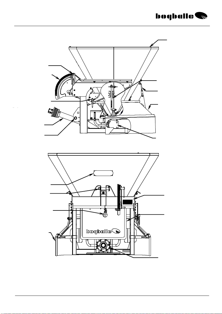
OVERVIEW
Hopper
Angle transmission
Alternatively: Oil motor
Parallel guiding axle
Agitator
Limiter
Setting scale
Fixture for
adjustment of
limiter
Setting pointer
Link pins
PTO-shaft
Connection Rod f/ shutter
Canvas Skirt
Friction clutch
Top link fixture
Serial No.
Inspection window
Mudguard

S-line
4
PRACTICAL USE
When driving with a full hopper it’s NOT recommended to drive on an uneven
surface for a longer period of time –this might cause the material to compact.
The tractor’s stabilization chains must be tightened in order to prevent the spreader
from swinging from side to side while driving.
When the shutter/outlet is closed the spreading disc should not rotate for a longer
period of time. The material will compress and cause heat development and
crushing of the agitator. The agitator can be damaged and involve overheat and
damage of the friction clutch.
When filling the hopper the material has to be filled in cautiously in a steady flow.
Don’t let the material fall in at once and from too high a position. Never put
pressure on the material by pressing the material into the hopper with a
mechanical/hydraulic shovel.
Never leave the spreader with material in the hopper. Not even overnight!
For example, road salt, which is hygroscopic, can by exposure to air of varying
humidity form a coherent mass / lump which might block the outlet of the machine
and prevent the agitator from rotating with possibly defective slip clutch or lack of
power from the oil motor to follow.
At a humidity of more than 75% a salt solution is formed on the salt crystals. If the
humidity is reduced again, the water evaporates and the salt re-crystallize resulting
in the formation of a coherent mass / lump.
VANE POSITION
The spread chart states the setting of the vanes, i.e.:
1,2,3,4 –or a combination.
Setting / position of the vanes is decisive for the distribution of the material.
Basically the vanes are set according to the spread chart, but in case the material
does not have the wanted distribution from side to side it can be necessary to
adjust the spread pattern by adjustment of the vane position.
oIf the vanes are adjusted against the running direction
(Higher figure), the quantity is increased to the spreader's right side
oIf the vanes are adjusted in the in the running direction
(Lower figure), the quantity is increased to the spreader's left side
oIn order to ensure an even distribution of the material it is often an advantage to set
the vanes in two different positions, for instance 2-3-2-3.
This should be done in such a way that the two vanes placed opposite to each
other are set in the same position.
S-line
5
oThe spreading vanes are set by loosening the vane bolts and then place and fix the
vane in the requested position.
In case the material is supposed to be distributed even more to the left side of
the spreader, the vane's inner fixture can be moved to track B.
PTO-RPMs
The spread chart states the PTO speed:
The PTO revolutions per minute are decisive for the spread width and are also
of importance for the distribution of the material.
If the PTO revolutions per minute are lower than the stated number of
revolutions –the spread width will be reduced and the sidewise distribution will
at the same time be increased to the right of the machine.
The operation of the agitator is directly depending on the number of revolutions
of the PTO. At a low revolution figure the operation of the agitator will be
reduced –at a too high revolution figure the agitator will be under too high
pressure, which involves increased wear and possible defect.
The stated PTO speed MUST be respected.
LIMITER
The spread chart states the respective settings of the limiter:
Minimum : Minimum spread width approx.
1 metre –skirt mounted.
Middle : Middle position marked at lock for
adjustment of the limiter.
Maximum : Max spread width with
limiter in upper position.
Limiter demounted : ÷ limiter is demounted when spreading
for instance mineral fertiliser.
The setting / position of the limiter is decisive for the spread width and can be
steeples adjusted until the required spread width is reached.
Pos 1
Track A,
Standard
Pos 4
Track B
Special
S-line
6
AGITATOR
When driven by PTO the rotation has to be started slowly with the tractor idling.
As standard the spreader is delivered with agitator for humid
SAND and SALT (Agitator with rubber disc).
The operation of the agitator is decisive for ensuring a constant
and uniform material flow.
Material for slippery roads is often difficult to handle because
the material can compress and build bridges with no flow as
result. See the paragraph: ”Special attention please”
The agitator is a wear part that must be checked now and then.
Wear will influence the efficiency of the agitator resulting in
smaller and at last no flow.
The primary wear parts are exchangable and made of hardened steel.
Pay attention to the fact that severe wear of the universal joint may cause
locking of the joint with overheat and defect friction clutch in the transmission
as consequence.
When spreading very rough material / small crushed stones or mineral fertiliser
the special free wheeling agitator is used (optional equipment).
When spreading dry smooth-running materials - for instance dry
salt or urea the special free wheeling agitator is also used.
oAlternatively the standard agitator’s axle is dismounted
(agitator axle with rubber disc) in a way that only the
lower ejector part is used. This solution might induce
crushing/grinding of the material.
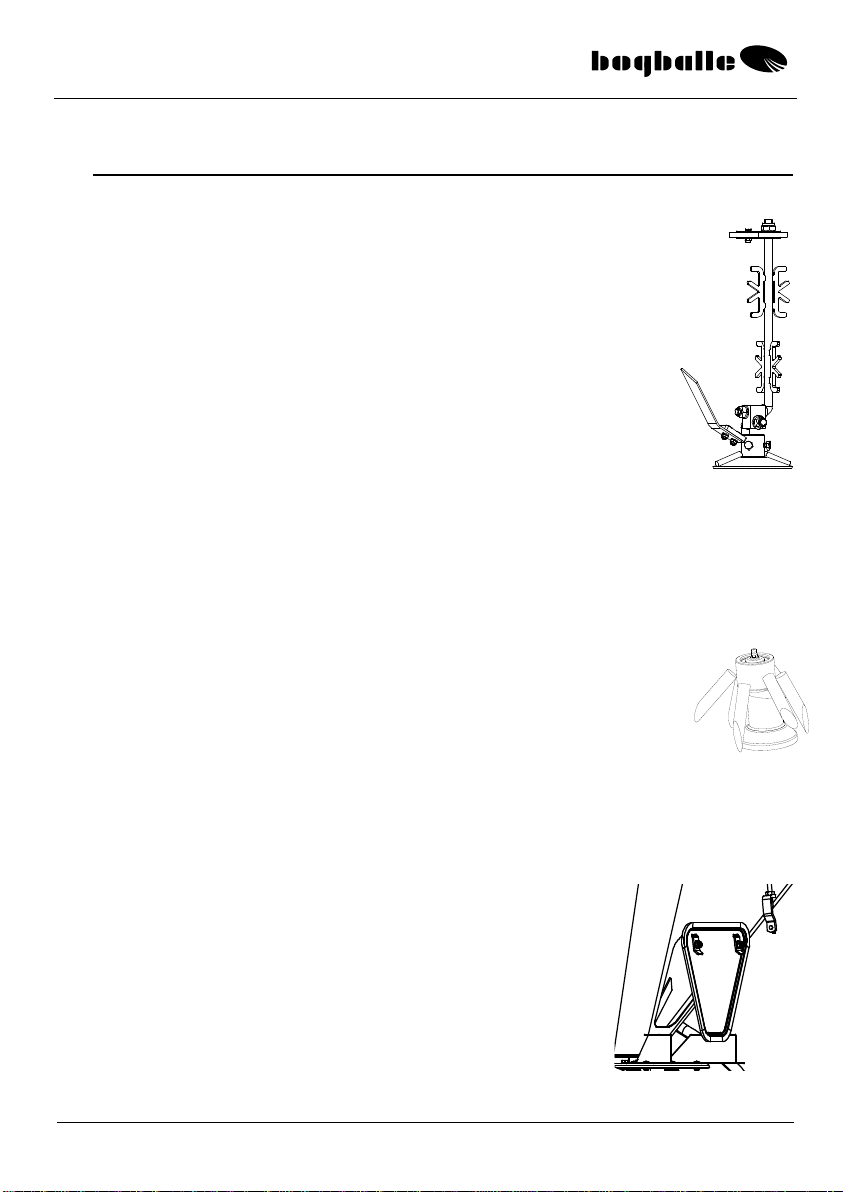
SERVICE WINDOW, S3
As an example the hopper's service window can be used
when servicing the spreader's agitator.
The tractor's motor always has to be stopped when the
service window is open!
↑
→
S-line
7
CHECK OF SPREADER - before use
The adjustment and closing shutters must be easy to move. Never
use force. If the system is not easy to move –the reason is often
lack of lubrication of the setting system’s moving part or desiccated
material remains.
The spreading discs must turn easily when the PTO is not
mounted. Alternatively when using oil motor with open flow.
The spreading vanes must be intact and correctly fixed.
The PTO shaft must be of correct length, with suitable
overlap of the axle ends (min. 50 mm.). If the overlap is too
long or too short it will result in a serious damage of the
transmission axle.
DO NOT lift the spreader higher than working height (60 CM).
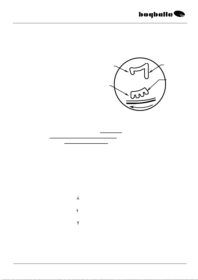
If the shaft is not of correct length –and if the
transmission is damaged, it will clearly appear from
”press marks ” on the splined axle.
If the axle is pressed, metal fatigue might cause damage after a
period of usage. Such damage is of course not under warranty!
Check that all the bolts are tightened –especially the
bolts securing the spreader’s hopper!
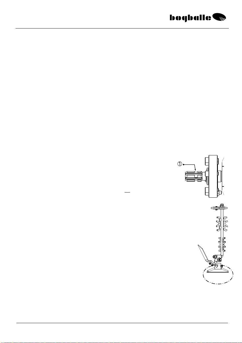
The lower part of the agitator is equipped with a
sealing –the distance between the sealing and the
bottom of the hopper has to be approx. 0,5 mm. If the
distance is larger the agitator/sealing has to be
adjusted to prevent leakage when spreading fine
materials. The adjustment is done via the agitator’s
two pointed screws.

S-line
8
TECHNICAL SPECIFICATIONS, general
Hopper volume
:
S2
S3
Hopper capacity
:
130, 240, 350
500, 775, 1.050
Litres
Spread width
:
Max. 600
Max. 1.600
Kg.
Spreading capacity
:
2 –8
2 –8
Metres
3-point linkage
:
Ca. 5 –350
App. 5 –350
G/M2
Kat. l/II / ISO 730/I
Kat. II / ISO 730/I
S2 / S3 hydra w/ Oil Motor
Oil pressure
:
Min. 120
Max. 140
Min. 140
Max. 175
Bar
Oil Flow
:
Min. 20
Max. 90
Min. 32
Max. 40
L/Min.
TECHNICAL SPECIFICATIONS, specific
SPECIFICATIONS
S2, 130 l
S2, 240 l
S2, 350 l
S3, 500 l
S3, 775 l
S3, 1.050
Load height
CM
77
96
115
115
133
152
Hopper volume
Litres
130
240
350
500
775
1.050
Hopper capacity, Max.
KG
175
325
470
675
1.045
1.600
Fill opening
CM
70 x 74
70 x 74
70 x 74
114 x 119
114 x 119
114 x 119
Net weight
KG
118
130
142
166
189
212
Total weight
KG
275
437
594
841
1.234
1.812
The hopper capacity is made from hopper volume in litres multiplied with a specific
weight of ~ 1,35 Kg/litres.
STANDARD EQUIPMENT
The S3 is from the factory supplied with the following standard equipment.
PTO Shaft / alternatively w/ oil motor
Agitator f/ Salt and Sand (w/ rubber disc)
Pressure Compensator for protection of agitator
Transmission, with friction / overload clutch (not w/ oil motor)
Spreading vanes
Limiter with skirt
Sieve, mesh size 5 x 5 cm

S-line
9
OPTIONAL EQUIPMENT
A line of useful optional equipment can be supplied –as mentioned below:
COMPONENT
DESCRIPTION
DIMENSION
Module S2
110 Litres
76 x 80
CM
Hopper Cover S2
Foldable
76 x 80
CM
Module S3
275 Litres
120 x 125
CM
Hopper Cover S3
Foldable
120 x 125
CM
Extension Handle
Manual Control
Remote Control of Quantity
Cable
Remote Control of Quantity
Hydraulic
Remote Control of Quantity
Electric motor, actuator
Remote Control of Spread Width
Electric motor, actuator
CALIBRATOR ICON
Ground Speed Related Quantity / Working Width
Traffic Lights
Special Agitator for Rough Material
All BOGBALLE products are subject to a continuous development. Therefore, the list might not always be up-to-date.
MAINTENANCE AND CARE
NORMAL MAINTENANCE
The BOGBALLE machine is manufactured in such a way that it requires a
minimum of maintenance.
In the construction it is considered that cleaning and lubrication can be completed
quickly and thoroughly –without taking apart the machine.
The surface treatment consists of a robust FlexiCoat powder paint –in addition all
essential wear parts and bolt assembling are made of stainless steel.
Many of the machine’s components are greased once and need no extra
maintenance, for instance the central and angle gears of the transmission.
The maintenance mentioned below is absolutely necessary!
”If the machine is maintained – it will still be new - in 5 years!”
”If the machine is not maintained –it will be old –next year!”
The machine must always be thoroughly cleaned after use. The
cleaning should be done with water perhaps including soap. When
using a high-pressure cleaner only use low pressure and do not
clean direct on the axle seals of the transmission and the oil motor.
Do not use grease-removing cleaning liquid –without giving the
machine –right after drying –an application of anti corrosion oil.

S-line
10
It is strongly recommended to grease the machine in a corrosion
protective liquid (for instance oil)–BEFORE using it first time.
Without protection, rust might arise within a few hours in
areas, where the paint has been damaged –salt is very
corrosive.
THEREFORE –generally the machine must be greased
daily in a corrosion protective liquid –when used.
The machine must also be greased before storing.
Please consider that cleaning products and corrosion protecting
liquids might include dissolvent that might dissolve the glue fixing the
transfers.
PROTECTION, Friction clutch
The transmission of the machine is equipped with friction / overload
clutch.
The friction clutch is a most important component protecting against
overload –and a damaged transmission and agitator.
The friction clutch must ”slip” at START of the tractor PTO.
If the clutch does not slip –the transmission will be damaged.
The friction clutch is in principle maintenance free, but minimum
once a year the torque must be checked –to make sure that the
torque is between 240 –300 Nm.
If the torque exceeds those limits, dismantle and clean the clutch
components as corrosion or wear might be the reason.
After mantling the clutch, check that the torque limits are within
the mentioned torque limits.
The friction clutch ”slips” approx. 1-2 turns at START of the tractor PTO. This reduces
the load on the components of the transmission to approx. 1/10 of the load to which the
transmission is exposed, if the coupling is not able to ”slip”.
It is always necessary to START the tractor PTO
”slowly / smoothly”!

S-line
11
LUBRICATION
The components below must be greased according to below
instruction.
See the explaining sketch in the paragraph ”OVERVIEW”.
LUBRICATION ONCE A DAY:
COMPONENT
INSTRUCTION
Cardan joint and lock of the PTO
Telescope axles of the PTO
Setting and closing shutter (Bottom of hopper)
Use grease
Use grease
Use grease
PARTS GREASED ONCE:
The angle gear is filled with special grease and needs no lubrication.
GENERALLY
A new machine will always ”move” a little bit in all nuts + bolts.
Therefore, all the machine’s nuts and bolts must be retightened -
first time it is put into operation –after 3 to 5 hours operation.
Exception is the angle gear’s bolts –these are locked and sealed
with Locktite.
Special attention is needed towards the spreader’s 6 M12 bolts
tightening the hopper –these are tightened with a 90 Nm torque.
Be aware that stainless nuts + bolts might ”weld together”. When
mounting such bolts –the thread must be greased with cutting
lubricant or copper grease!
SPREADING VANES
The vanes will be worn due to the material. Therefore, the vanes are
to be considered a wearing part –that must be exchanged
dependent on the quantity and type of material.
Always clean the contact surfaces of the vanes and the
spreading disc for dust etc –before mounting and tightening
the vane!
IF HOLES ARE WORN IN THE VANES THEY MUST BE EXCHANGED AT ONCE!

S-line
12
GUARANTEE / RESPONSIBILITY
Claim conditions are according to Danish legislation. Service and repair are
made free of cost within 12 months from date of purchase on the following
conditions:
That the failure is due to construction or material faults
(Normal wear, missing maintenance and misuse not included).
That the failure is not due to not original components / equipments.
That persons with no technical knowledge to the machine have not tried to repair.
Compensation for person or crop injury does not fall on the supplier.
GENERALLY
This machine is intended for spreading sand, salt, urea and the like on icy roads
and in special cases fertilisers.
Spreading of other flowing materials might also be possible. If so we draw the
attention to data list of the material concerned in order to determine possible safety
or health measures to be taken to minimize any risks.
If the machine is used for spreading material which is not defined in the spread
charts for the spreader, the manufacturer of the machine can never be held
responsible.
SAFETY and PROTECTION
The transmission system of the machine:
PTO shaft, friction clutch and spreading discs w/ vanes –must be considered ”as
dangerous”, and absolute care must be taken with these machine parts, especially
in connection with rotation of the tractor PTO system.
DO NOT LEAVE THE TRACTOR CABIN –WITHOUT STOPPING THE PTO
SYSTEM OF THE TRACTOR!
Never go behind the machine –with rotating spreading discs.
Never clean the machine - with rotating spreading discs.
Never put hand/object into the hopper –with rotating spreading discs.
Always check that the spreading vanes are correctly fixed.
Check that the protection tubes of the PTO are intact.
Check that the security chain of the PTO is fixed.
Check that top link and top link pins are intact and secured by lynch pin.

S-line
13
Using the Calibration Kit
Limiter and canvas skirt is used as calibration kit.
Put the limiter in the lowest position with the canvas skirt mounted.
The calibration kit is used for stationary calibration, so that the machine is adjusted
precisely in comparison to the nature of the material in question.
There may be big differences in the material dependent on temperature, humidity
and other climate factors.
Be aware that the nature of the material may vary from supply to supply. It is
therefore recommended to make a calibration test for each new supply.
Is the hopper wet on the inside, the humidity will prevent the fertiliser from falling
down. In such cases minimum 3 calibrations must be made –where the last
calibration quantity is valid.
The calibration kit is also used if the material is not found in the spread chart.
PROCEDURE:
1. The scale stop is fixed at 4,5 on the spreader’s scale
2. Let the PTO-shaft rotate at 400 rpm.
(The materials flow is dependent on the PTO rotations)
3. A calibration test is performed for exactly 30 sec.
(The spreader’s outlet is opened for 30 sec.).
4. The calibration value is weighed
5. The fertiliser’s Flow Factor is calculated cf. the below formula:
Quantity [g/m2] x Spread width [M] x Speed [Km/h] x 20
Calibration value [Kg/30 sec.]
6. In the Flow Factor list on the next page you can find the Flow Factor closest to
the calculated Flow Factor –read off the scale figure or use the Flow Factor
directly and adjust the spreader’s scale.
Symbol explanation:
[Kg/Ha]
:
The wanted quantity
[M]
:
Spread width
[Km/h]
:
Speed
:
Calibration value after 30 sec. at scale figure 4,5
:
Scale 0-9, Flow Factor 645-6575
S-line
14
Flow Factor Calculation
4,5
PTO
400 rpm
[g/m2] x [M] x [Km/h] x 20
[Kg]
=
Flow Factor
[g/m2]
[M]
[Km/t]
Kg
Flow
Factor
Rough Road Salt
:
21
X
6
X
15
/
15
=
2520 ►
4,3
:
X
X
/
=
►
:
X
X
/
=
►
:
X
X
/
=
►
:
X
X
/
=
►
:
X
X
/
=
►
:
X
X
/
=
►
:
X
X
/
=
►
:
X
X
/
=
►
:
X
X
/
=
►
Flow
Factor
Flow
Factor
F
L
O
W
F
A
C
T
O
R
0,0
1380
3,0
4080
6,0
0,1
1470
3,1
4170
6,1
0,2
1560
3,2
4260
6,2
0,3
1650
3,3
4350
6,3
0,4
1740
3,4
4440
6,4
0,5
1830
3,5
4530
6,5
0,6
1920
3,6
4620
6,6
0,7
2010
3,7
4710
6,7
0,8
2100
3,8
4800
6,8
0,9
2190
3,9
4890
6,9
1,0
2280
4,0
4980
7,0
1,1
2370
4,1
5065
7,1
1,2
2460
4,2
5150
7,2
1,3
2550
►4,3
5235
7,3
1,4
2640
4,4
5320
7,4
1,5
2730
4,5
5405
7,5
1,6
2820
4,6
5490
7,6
1,7
2910
4,7
5575
7,7
1,8
3000
4,8
5655
7,8
1,9
3090
4,9
5735
7,9
645
2,0
3180
5,0
5815
8,0
715
2,1
3270
5,1
5895
8,1
785
2,2
3360
5,2
5975
8,2
855
2,3
3450
5,3
6050
8,3
930
2,4
3540
5,4
6125
8,4
1005
2,5
3630
5,5
6200
8,5
1080
2,6
3720
5,6
6275
8,6
1155
2,7
3810
5,7
6350
8,7
1230
2,8
3900
5,8
6425
8,8
1305
2,9
3990
5,9
6500
8,9
►
►
30 sec.
▼

S-line
15
S2-Trail
OVERVIEW
Setting of working
width
Agitator type
Clutch f/ spreading disc
and agitator
Serial No.
Transmission
Setting scale
Handle f/
disengagement
Setting pointer
Drawbar
Lock/adjustment
f/ limiter
Top link
Wheel

S-line
16
PRACTICAL USE
When setting the spreading system of the machine, say vane setting, PTO speed
and limiter, see the paragraph ’PRACTICAL USE’ S2 / S3.
S2 Trail reaches its maximum spread width at 16 Km/h –corresponding to 400
rpms/min. on the spreading disc of the machine. It's not recommended to go faster
than 16 Km/h when spreading as it'll reduce the agitator's functionality and service
life.
Mount the spreader in the draw bar of the pulling vehicle.
The top link of the machine is adjusted in such a way that the spreading disc is
horizontal.
Check that the spreading disc is running easily and that shutter and setting
handle are easy to move.
Take away hard lumps and especially stones.
When driving with a full hopper it is NOT recommended to drive on an uneven
surface for a longer period of time –this might cause the material to compact.
Agitator and spreading disc must be disengaged if more than 100 m are driven
with closed shutter (Avoid if possible that agitator and spreading disc are rotating when the shutter is closed)
Spreading disc and agitator can with advantage be disengaged instead of
closing the shutter –as most types of material stay in the hopper when the
agitator do not rotate.
AGITATOR
Agitator and spreading disc are engaged when the spreader
is stopped.
The spreader is standard supplied with agitator for humit SAND
and SALT (Agitator with rubber disc and rubber fingers).
When spreading very rough material / small crushed stones the
free wheeling agitator is used (Optional equipment).
When spreading dry smooth-running materials –for instance dry salt or urea
the special free wheeling agitator is also used.
oAlternatively the standard agitator’s axle is dismounted (agitator axle
with rubber disc) in a way that only the lower ejector part is used. This
solution might induce crushing/grinding of the material.

S-line
17
Wheel slip
The S2 Trail spreading system is operated by the left wheel of the spreader. In
case the ground is icy and the spreading material is compact –wheel slip may
arise. (The wheel slides on the ground.)
In such cases the following check and changes are recommended:
It must be ensured that no bigger foreign objects in the hopper are causing
blocking of the agitator.
Open the setting handle 100% (scale 9,0) so that possible compacted material
is loosened when driving.
Reduce the air pressure in the pulling tyre for better road grip.
Mounting of a Snow Sock on the pulling wheel (Snow Socks are optional
equipment)
Put spikes in the pulling wheel. (Spike tyre is optional equipment).
Engagement of the spreading system can, if necessary, be made at low speed
less than 5 km/h. Only recommended on icy roads.
Do not mount snow chains
Forward speed for S2 Trail
The spreader should not drive more than 25 Km/h.
Transport only with disengaged spreading system / agitator.
Pay attention to the fact that the S2 trail may ‘tilt’ if the hopper is full and the
machine is driving on a slope or in a sharp turn at speeds higher than 8 km/h.

S-line
18
TECHNICAL DATA, general
S2 Trail
Hopper volume
:
130, 240, 350
Litres
Hopper capacity
:
Max. 600
Kg.
Spread width
:
1 –8
Meter
Spreading capacity
:
Ca. 5 –350
g/m2
TECHNICAL DATA, specific
SPECIFIKATION
S2 Trail, 130 l
S2 Trail, 240 l
S2 Trail, 350 l
Load height
cm
115
133
152
Hopper volume
Litres
130
240
350
Hopper capacity, Max.
Kg
175
325
470
Hopper opening
cm
70 x 74
70 x 74
70 x 74
Net weight
Kg
150
162
174
Total weight
Kg
325
487
600
The hopper capacity is made from hopper volume in litres multiplied with a specific weight of ~ 1,35
Kg/litres. STANDARD EQUIPMENT
The S2 Trail is from the factory supplied with the following standard
equipment.
Agitator f/ Salt and f/ Sand (w/ rubber disc and rubber fingers)
Transmission, with cable operation for disengagement of spreading disc.
Spreading vanes
Limiter w/ canvas skirt
Sieve, mesh size 5 x 5 cm
Manual setting of quantity
OPTIONAL EQUIPMENT
A line of useful optional equipment can be supplied –as mentioned below:
COMPONENT
DESCRIPTION
DIMENSION
Module S2
110 litres
76 x 80
Cm
Hopper cover S2
Tiltable
76 x 80
Cm
Cable control of quantity
Remote control of quantity
Hydraulic
Remote control of quantity
Electric motor, actuator
Remote control of quantity
Electric motor, actuator
CALIBRATOR ICON
Ground speed related quantity / working width
Traffic lights
Special agitator for rough material
Spike tyre
Better friction on icy surfaces
Snow Sock
Better friction on snow-covered surfaces
All BOGBALLE products are subject to a continuous development. Therefore the list might not always be up-to-date.

S-line
19
EC-Declaration of Conformity
Manufacturer:
BOGBALLE A/S
Bogballe · DK-7171 Uldum
Phone +45 7589 3266 Fax +45 7589 3766
Declares that machine:
Sand and salt spreader:
S2 / S3
Is made in conformity with:
directive of 17th May 2006 conc. mutual approximation of the laws of the member states on
machines (2006/42/EØF), with special reference to the enclosure II, A and enclosure I of the
directive, conc. essential safety and health claims in connection with construction and
manufacture of machines.
International/national standards:
DS/EN ISO 12100
DS/EN ISO 13857 1st edition –2008.03.26
DS/EN 349
ISO 500, 1st edition –2004.02.01
DS/EN ISO 4254-1 :2008
DS/EN ISO 4254-8 :2018
When mounted with CALIBRATOR:
Is made in conformity with:
directive of 15th December 2004 conc. mutual approximation of the laws of the member states on
electromagnetic compatibility (2004/108/EØF)
International/national standards:
DS/EN ISO 14982 :2009
DS/EN 61000-6-3 :2007
DS/EN 61000-6-4 :2007
Bogballe, 2018-08-27
Nils Jørn Laursen
This manual suits for next models
2
Table of contents
Other BOGBALLE Spreader manuals


